Download presentation
Presentation is loading. Please wait.

1
Chapter 1 Software and Software Engineering
Dual role of software Software questions haven't changed A definition of software Differences between hardware and software Changing nature of software Dealing with legacy software Software myths (Source: Pressman, R. Software Engineering: A Practitioner’s Approach. McGraw-Hill, 2005)
")
2
Dual Role of Software Both a product and a vehicle for delivering a product Product Delivers computing potential Produces, manages, acquires, modifies, display, or transmits information Vehicle Supports or directly provides system functionality Controls other programs (e.g., operating systems) Effects communications (e.g., networking software) Helps build other software (e.g., software tools)
 Effects communications (e.g., networking software) Helps build other software (e.g., software tools)")
3
Questions About Software Haven't Changed Over the Decades
Why does it take so long to get software finished? Why are development costs so high? Why can't we find all errors before we give the software to our customers? Why do we spend so much time and effort maintaining existing programs? Why do we continue to have difficulty in measuring progress as software is being developed and maintained?

4
A Definition of Software (all inclusive)
Instructions (computer programs) that when executed provide desired features, function, and performance Data structures that enable the programs to adequately manipulate information Documents that describe the operation and use of the programs
 that when executed provide desired features, function, and performance. Data structures that enable the programs to adequately manipulate information. Documents that describe the operation and use of the programs.")
5
Differences between Software and Hardware
Software is developed or engineered; it is not manufactured in the classical sense Impacts the management of software projects Software doesn't wear out Hardware bathtub curve compared to the software ascending spiked curve Although the industry is moving toward component-based construction, most software continues to be custom built (it is still complex to build)
")
6
Software Failure Curve

7
Changing Nature of Software
System software Application software Engineering/scientific software Embedded software Product-line software (e.g., inventory control, word processing, multimedia) Web applications Artificial intelligence software Ubiquitous computing (small, wireless devices) Netsourcing (net-wide computing) Open source (operating systems, databases, development environments) The ".com" marketing applications
 Web applications. Artificial intelligence software. Ubiquitous computing (small, wireless devices) Netsourcing (net-wide computing) Open source (operating systems, databases, development environments) The .com marketing applications.")
8
Legacy Software - Characteristics
Support core business functions Have longevity and business criticality Exhibit poor quality Convoluted code, poor documentation, poor testing, poor change management

9
Reasons for Evolving the Legacy Software
(Adaptive) Must be adapted to meet the needs of new computing environments or more modern systems, databases, or networks (Perfective) Must be enhanced to implement new business requirements (Corrective) Must be changed because of errors found in the specification, design, or implementation (Note: These are also the three major reasons for any software maintenance)
 Must be adapted to meet the needs of new computing environments or more modern systems, databases, or networks. (Perfective) Must be enhanced to implement new business requirements. (Corrective) Must be changed because of errors found in the specification, design, or implementation. (Note: These are also the three major reasons for any software maintenance)")
10
Software Myths - Management
"We already have a book that is full of standards and procedures for building software. Won't that provide my people with everything they need to know?" Not used, not up to date, not complete, not focused on quality, time, and money "If we get behind, we can add more programmers and catch up" Adding people to a late software project makes it later Training time, increased communication lines "If I decide to outsource the software project to a third party, I can just relax and let that firm build it" Software projects need to be controlled and managed

11
Software Myths - Customer
"A general statement of objectives is sufficient to begin writing programs – we can fill in the details later" Ambiguous statement of objectives spells disaster "Project requirements continually change, but change can be easily accommodated because software is flexible" Impact of change depends on where and when it occurs in the software life cycle (requirements analysis, design, code, test)
")
12
Software Myths - Practitioner
"Once we write the program and get it to work, our job is done" 60% to 80% of all effort expended on software occurs after it is delivered "Until I get the program running, I have no way of assessing its quality Formal technical reviews of requirements analysis documents, design documents, and source code (more effective than actual testing) "The only deliverable work product for a successful project is the working program" Software, documentation, test drivers, test results "Software engineering will make us create voluminous and unnecessary documentation and will invariably slow us down" Creates quality, not documents; quality reduces rework and provides software on time and within the budget
 The only deliverable work product for a successful project is the working program Software, documentation, test drivers, test results. Software engineering will make us create voluminous and unnecessary documentation and will invariably slow us down Creates quality, not documents; quality reduces rework and provides software on time and within the budget. ")
13
Chapter 2 The Software Process
Software engineering defined A layered technology Process, methods, and tools Generic process framework Umbrella activities Capability Maturity Model (SW-CMM) (Source: Pressman, R. Software Engineering: A Practitioner’s Approach. McGraw-Hill, 2005)
 (Source: Pressman, R. Software Engineering: A Practitioner’s Approach. McGraw-Hill, 2005)")
14
Software Engineering - Defined
(1969) Software engineering is the establishment and use of sound engineering principles in order to obtain economically software that is reliable and works efficiently on real machines (IEEE) The application of a systematic, disciplined, quantifiable approach to the development, operation, and maintenance of software; that is, the application of engineering to software
 Software engineering is the establishment and use of sound engineering principles in order to obtain economically software that is reliable and works efficiently on real machines. (IEEE) The application of a systematic, disciplined, quantifiable approach to the development, operation, and maintenance of software; that is, the application of engineering to software.")
15
Software Engineering is a Layered Technology
Tools Methods Processes Quality Focus

16
Process, Methods, and Tools
Provides the glue that holds the layers together; enables rational and timely development; provides a framework for effective delivery of technology; forms the basis for management; provides the context for technical methods, work products, milestones, quality measures, and change management Methods Provide the technical "how to" for building software; rely on a set of basic principles; encompass a broad array of tasks; include modeling activities Tools Provide automated or semi-automated support for the process and methods (i.e., CASE tools)
")
17
Generic Process Framework
Communication Involves communication among the customer and other stake holders; encompasses requirements gathering Planning Establishes a plan for software engineering work; addresses technical tasks, resources, work products, and work schedule Modeling (Analyze, Design) Encompasses the creation of models to better understand the requirements and the design Construction (Code, Test) Combines code generation and testing to uncover errors Deployment Involves delivery of software to the customer for evaluation and feedback
 Encompasses the creation of models to better understand the requirements and the design. Construction (Code, Test) Combines code generation and testing to uncover errors. Deployment. Involves delivery of software to the customer for evaluation and feedback.")
18
Umbrella Activities Software requirements management
Software project planning Software project tracking and oversight Software quality assurance Software configuration management Software subcontract management Formal technical reviews Risk management Measurement – process, project, product Reusability management (component reuse) Work product preparation and production
 Work product preparation and production.")
19
What is a Process? (Webster) A system of operations in producing something; a series of actions, changes, or functions that achieve an end or a result (IEEE) A sequence of steps performed for a given purpose
 A system of operations in producing something; a series of actions, changes, or functions that achieve an end or a result. (IEEE) A sequence of steps performed for a given purpose.")
20
What is a Software Process?
(SEI) A set of activities, methods, practices, and transformations that people use to develop and maintain software and the associated products (e.g., project plans, design documents, code, test cases, and user manuals) As an organization matures, the software process becomes better defined and more consistently implemented throughout the organization Software process maturity is the extent to which a specific process is explicitly defined, managed, measured, controlled, and effective
 A set of activities, methods, practices, and transformations that people use to develop and maintain software and the associated products (e.g., project plans, design documents, code, test cases, and user manuals) As an organization matures, the software process becomes better defined and more consistently implemented throughout the organization. Software process maturity is the extent to which a specific process is explicitly defined, managed, measured, controlled, and effective.")
21
Capability Maturity Model (SW-CMM)
Developed in 1987 by the Software Engineering Institute (SEI) at Carnegie-Mellon University under the sponsorship of DARPA Described in the book Managing the Software Process in 1989 by Watts Humphrey Published as a separate document: Capability Maturity Model for Software in 1991
 at Carnegie-Mellon University under the sponsorship of DARPA. Described in the book Managing the Software Process in 1989 by Watts Humphrey. Published as a separate document: Capability Maturity Model for Software in")
22
Immature Software Organizations
Software processes are generally improvised If a process is specified, it is not rigorously followed or enforced The software organization is reactionary Managers only focus on solving immediate (crisis) problems Schedules and budgets are routinely exceeded because they are not based on realistic estimates When hard deadlines are imposed, product functionality and quality are often compromised There is no basis for judging process quality or for solving product or process problems Activities such as reviews and testing are curtailed or eliminated when projects fall behind schedule
 problems. Schedules and budgets are routinely exceeded because they are not based on realistic estimates. When hard deadlines are imposed, product functionality and quality are often compromised. There is no basis for judging process quality or for solving product or process problems. Activities such as reviews and testing are curtailed or eliminated when projects fall behind schedule.")
23
Five Levels of Software Process Maturity

24
Characteristics of Each Level
Initial Level (Level 1) Characterized as ad hoc, and occasionally even chaotic Few processes are defined, and success depends on individual effort Repeatable (Level 2) Basic project management processes are established to track cost, schedule, and functionality The necessary process discipline is in place to repeat earlier successes on projects with similar applications
 Characterized as ad hoc, and occasionally even chaotic. Few processes are defined, and success depends on individual effort. Repeatable (Level 2) Basic project management processes are established to track cost, schedule, and functionality. The necessary process discipline is in place to repeat earlier successes on projects with similar applications.")
25
Characteristics of Each Level (continued)
Defined (Level 3) The software process for both management and engineering activities is documented, standardized, and integrated into a standard software process for the organization All projects use an approved, tailored version of the organization's standard software process for developing and maintaining software Managed (Level 4) Detailed measures of the software process and product quality are collected Both the software process and products are quantitatively understood and controlled
 The software process for both management and engineering activities is documented, standardized, and integrated into a standard software process for the organization. All projects use an approved, tailored version of the organization s standard software process for developing and maintaining software. Managed (Level 4) Detailed measures of the software process and product quality are collected. Both the software process and products are quantitatively understood and controlled.")
26
Characteristics of Each Level (continued)
Optimized (Level 5) Continuous process improvement is enabled by quantitative feedback from the process and from piloting innovative ideas and technologies
 Continuous process improvement is enabled by quantitative feedback from the process and from piloting innovative ideas and technologies.")
27
Visibility into the Software Process

28
Probability of Schedule and Budget

29
The CMM Structure

30
Key Process Areas

31
Software Process Assessments

32
Chapter 3 Prescriptive Process Models
Generic process framework (revisited) Traditional process models Specialized process models The unified process (Source: Pressman, R. Software Engineering: A Practitioner’s Approach. McGraw-Hill, 2005)
 Traditional process models. Specialized process models. The unified process. (Source: Pressman, R. Software Engineering: A Practitioner’s Approach. McGraw-Hill, 2005)")
33
Generic Process Framework
Communication Involves communication among the customer and other stake holders; encompasses requirements gathering Planning Establishes a plan for software engineering work; addresses technical tasks, resources, work products, and work schedule Modeling (Analyze, Design) Encompasses the creation of models to better under the requirements and the design Construction (Code, Test) Combines code generation and testing to uncover errors Deployment Involves delivery of software to the customer for evaluation and feedback 33
 Encompasses the creation of models to better under the requirements and the design. Construction (Code, Test) Combines code generation and testing to uncover errors. Deployment. Involves delivery of software to the customer for evaluation and feedback. 33.")
34
Modeling: Software Requirements Analysis
Helps software engineers to better understand the problem they will work to solve Encompasses the set of tasks that lead to an understanding of what the business impact of the software will be, what the customer wants, and how end-users will interact with the software Uses a combination of text and diagrams to depict requirements for data, function, and behavior Provides a relatively easy way to understand and review requirements for correctness, completeness and consistency 34

35
Modeling: Software Design
Brings together customer requirements, business needs, and technical considerations to form the “blueprint” for a product Creates a model that that provides detail about software data structures, software architecture, interfaces, and components that are necessary to implement the system Architectural design Represents the structure of data and program components that are required to build the software Considers the architectural style, the structure and properties of components that constitute the system, and interrelationships that occur among all architectural components User Interface Design Creates an effective communication medium between a human and a computer Identifies interface objects and actions and then creates a screen layout that forms the basis for a user interface prototype Component-level Design Defines the data structures, algorithms, interface characteristics, and communication mechanisms allocated to each software component 35

36
Traditional Process Models

37
Prescriptive Process Model
Defines a distinct set of activities, actions, tasks, milestones, and work products that are required to engineer high-quality software The activities may be linear, incremental, or evolutionary 37

38
Waterfall Model (Diagram)
Communication Project initiation Requirements gathering Planning Estimating Scheduling Tracking Modeling Analysis Design Construction Code Test Deployment Delivery Support Feedback 38

39
Waterfall Model (Description)
Oldest software lifecycle model and best understood by upper management Used when requirements are well understood and risk is low Work flow is in a linear (i.e., sequential) fashion Used often with well-defined adaptations or enhancements to current software 39
 fashion. Used often with well-defined adaptations or enhancements to current software. 39.")
40
Waterfall Model (Problems)
Doesn't support iteration, so changes can cause confusion Difficult for customers to state all requirements explicitly and up front Requires customer patience because a working version of the program doesn't occur until the final phase Problems can be somewhat alleviated in the model through the addition of feedback loops (see the next slide) 40
 40.")
41
Waterfall Model with Feedback (Diagram)
Communication Project initiation Requirements gathering Planning Estimating Scheduling Tracking Modeling Analysis Design Construction Code Test Deployment Delivery Support Feedback 41

42
Incremental Model (Diagram)
Communication Planning Modeling Construction Deployment Increment #2 Communication Planning Modeling Construction Deployment Increment #3 Communication Planning Modeling Construction Deployment 42

43
Incremental Model (Description)
Used when requirements are well understood Multiple independent deliveries are identified Work flow is in a linear (i.e., sequential) fashion within an increment and is staggered between increments Iterative in nature; focuses on an operational product with each increment Provides a needed set of functionality sooner while delivering optional components later Useful also when staffing is too short for a full-scale development 43
 fashion within an increment and is staggered between increments. Iterative in nature; focuses on an operational product with each increment. Provides a needed set of functionality sooner while delivering optional components later. Useful also when staffing is too short for a full-scale development. 43.")
44
Prototyping Model (Diagram)
Quick Planning Communication Start Modeling Quick Design Deployment, Delivery, and Feedback Construction Of Prototype 44

45
Prototyping Model (Description)
Follows an evolutionary and iterative approach Used when requirements are not well understood Serves as a mechanism for identifying software requirements Focuses on those aspects of the software that are visible to the customer/user Feedback is used to refine the prototype 45

46
Prototyping Model (Potential Problems)
The customer sees a "working version" of the software, wants to stop all development and then buy the prototype after a "few fixes" are made Developers often make implementation compromises to get the software running quickly (e.g., language choice, user interface, operating system choice, inefficient algorithms) Lesson learned Define the rules up front on the final disposition of the prototype before it is built In most circumstances, plan to discard the prototype and engineer the actual production software with a goal toward quality 46
 Lesson learned. Define the rules up front on the final disposition of the prototype before it is built. In most circumstances, plan to discard the prototype and engineer the actual production software with a goal toward quality. 46.")
47
Spiral Model (Diagram)
Planning Communication Modeling Start Start Deployment Construction 47

48
Spiral Model (Description)
Invented by Dr. Barry Boehm in 1988 while working at TRW Follows an evolutionary approach Used when requirements are not well understood and risks are high Inner spirals focus on identifying software requirements and project risks; may also incorporate prototyping Outer spirals take on a classical waterfall approach after requirements have been defined, but permit iterative growth of the software Operates as a risk-driven model…a go/no-go decision occurs after each complete spiral in order to react to risk determinations Requires considerable expertise in risk assessment Serves as a realistic model for large-scale software development 48

49
General Weaknesses of Evolutionary Process Models
Prototyping poses a problem to project planning because of the uncertain number of iterations required to construct the product Evolutionary software processes do not establish the maximum speed of the evolution If too fast, the process will fall into chaos If too slow, productivity could be affected Software processes should focus first on flexibility and extensibility, and second on high quality We should prioritize the speed of the development over zero defects Extending the development in order to reach higher quality could result in late delivery 49

50
Specialized Process Models

51
Component-based Development Model
Consists of the following process steps Available component-based products are researched and evaluated for the application domain in question Component integration issues are considered A software architecture is designed to accommodate the components Components are integrated into the architecture Comprehensive testing is conducted to ensure proper functionality Relies on a robust component library Capitalizes on software reuse, which leads to documented savings in project cost and time 51

52
Formal Methods Model (Description)
Encompasses a set of activities that leads to formal mathematical specification of computer software Enables a software engineer to specify, develop, and verify a computer-based system by applying a rigorous, mathematical notation Ambiguity, incompleteness, and inconsistency can be discovered and corrected more easily through mathematical analysis Offers the promise of defect-free software Used often when building safety-critical systems 52

53
Formal Methods Model (Challenges)
Development of formal methods is currently quite time-consuming and expensive Because few software developers have the necessary background to apply formal methods, extensive training is required It is difficult to use the models as a communication mechanism for technically unsophisticated customers 53

54
The Unified Process

55
Background Birthed during the late 1980's and early 1990s when object-oriented languages were gaining wide-spread use Many object-oriented analysis and design methods were proposed; three top authors were Grady Booch, Ivar Jacobson, and James Rumbaugh They eventually worked together on a unified method, called the Unified Modeling Language (UML) UML is a robust notation for the modeling and development of object- oriented systems UML became an industry standard in 1997 However, UML does not provide the process framework, only the necessary technology for object-oriented development 55
 UML is a robust notation for the modeling and development of object- oriented systems. UML became an industry standard in However, UML does not provide the process framework, only the necessary technology for object-oriented development. 55.")
56
Background (continued)
Booch, Jacobson, and Rumbaugh later developed the unified process, which is a framework for object-oriented software engineering using UML Draws on the best features and characteristics of conventional software process models Emphasizes the important role of software architecture Consists of a process flow that is iterative and incremental, thereby providing an evolutionary feel Consists of five phases: inception, elaboration, construction, transition, and production 56

57
Phases of the Unified Process
Elaboration Inception planning modeling communication construction Construction deployment Transition Production 57

58
Inception Phase Encompasses both customer communication and planning activities of the generic process Business requirements for the software are identified A rough architecture for the system is proposed A plan is created for an incremental, iterative development Fundamental business requirements are described through preliminary use cases A use case describes a sequence of actions that are performed by a user 58

59
Elaboration Phase Encompasses both the planning and modeling activities of the generic process Refines and expands the preliminary use cases Expands the architectural representation to include five views Use-case model Analysis model Design model Implementation model Deployment model Often results in an executable architectural baseline that represents a first cut executable system The baseline demonstrates the viability of the architecture but does not provide all features and functions required to use the system 59

60
Construction Phase Encompasses the construction activity of the generic process Uses the architectural model from the elaboration phase as input Develops or acquires the software components that make each use-case operational Analysis and design models from the previous phase are completed to reflect the final version of the increment Use cases are used to derive a set of acceptance tests that are executed prior to the next phase 60

61
Transition Phase Encompasses the last part of the construction activity and the first part of the deployment activity of the generic process Software is given to end users for beta testing and user feedback reports on defects and necessary changes The software teams create necessary support documentation (user manuals, trouble-shooting guides, installation procedures) At the conclusion of this phase, the software increment becomes a usable software release 61
 At the conclusion of this phase, the software increment becomes a usable software release. 61.")
62
Production Phase Encompasses the last part of the deployment activity of the generic process On-going use of the software is monitored Support for the operating environment (infrastructure) is provided Defect reports and requests for changes are submitted and evaluated 62
 is provided. Defect reports and requests for changes are submitted and evaluated. 62.")
63
Unified Process Work Products
Work products are produced in each of the first four phases of the unified process In this course, we will concentrate on the analysis model and the design model work products Analysis model includes Scenario-based model, class-based model, and behavioral model Design model includes Component-level design, interface design, architectural design, and data/class design 63

64
Chapter 5 Software Engineering Practice
Communication practices Planning practices Analysis modeling practices Design modeling practices Construction practices Deployment practices (Source: Pressman, R. Software Engineering: A Practitioner’s Approach. McGraw-Hill, 2005)
")
65
Software Engineering Practice
Consists of a collection of concepts, principles, methods, and tools that a software engineer calls upon on a daily basis Equips managers to manage software projects and software engineers to build computer programs Provides necessary technical and management how to’s in getting the job done Transforms a haphazard unfocused approach into something that is more organized, more effective, and more likely to achieve success

66
The Essence of Problem Solving
Understand the problem (communication and analysis) Who has a stake in the solution to the problem? What are the unknowns (data, function, behavior)? Can the problem be compartmentalized? Can the problem be represented graphically? Plan a solution (planning, modeling and software design) Have you seen similar problems like this before? Has a similar problem been solved and is the solution reusable? Can subproblems be defined and are solutions available for the subproblems? (more on next slide)
 Who has a stake in the solution to the problem What are the unknowns (data, function, behavior) Can the problem be compartmentalized Can the problem be represented graphically Plan a solution (planning, modeling and software design) Have you seen similar problems like this before Has a similar problem been solved and is the solution reusable Can subproblems be defined and are solutions available for the subproblems (more on next slide)")
67
The Essence of Problem Solving (continued)
Carry out the plan (construction; code generation) Does the solution conform to the plan? Is the source code traceable back to the design? Is each component of the solution correct? Has the design and code been reviewed? Examine the results for accuracy (testing and quality assurance) Is it possible to test each component of the solution? Does the solution produce results that conform to the data, function, and behavior that are required?
 Does the solution conform to the plan Is the source code traceable back to the design Is each component of the solution correct Has the design and code been reviewed Examine the results for accuracy (testing and quality assurance) Is it possible to test each component of the solution Does the solution produce results that conform to the data, function, and behavior that are required")
68
Seven Core Principles for Software Engineering
Remember the reason that the software exists The software should provide value to its users and satisfy the requirements Keep it simple, stupid (KISS) All design and implementation should be as simple as possible Maintain the vision of the project A clear vision is essential to the project’s success Others will consume what you produce Always specify, design, and implement knowing that someone else will later have to understand and modify what you did Be open to the future Never design yourself into a corner; build software that can be easily changed and adapted Plan ahead for software reuse Reuse of software reduces the long-term cost and increases the value of the program and the reusable components Think, then act Placing clear, complete thought before action will almost always produce better results
 All design and implementation should be as simple as possible. Maintain the vision of the project. A clear vision is essential to the project’s success. Others will consume what you produce. Always specify, design, and implement knowing that someone else will later have to understand and modify what you did. Be open to the future. Never design yourself into a corner; build software that can be easily changed and adapted. Plan ahead for software reuse. Reuse of software reduces the long-term cost and increases the value of the program and the reusable components. Think, then act. Placing clear, complete thought before action will almost always produce better results.")
69
Communication Practices (Requirements Elicitation)
Project initiation Requirements gathering Planning Estimating Scheduling Tracking Modeling Analysis Design Construction Code Test Deployment Delivery Support Feedback 69

70
Communication Principles
Listen to the speaker and concentrate on what is being said Prepare before you meet by researching and understanding the problem Someone should facility the meeting and have an agenda Face-to-face communication is best, but also have a document or presentation to focus the discussion Take notes and document decisions Strive for collaboration and consensus Stay focused on a topic; modularize your discussion If something is unclear, draw a picture Move on to the next topic a) after you agree to something, b) if you cannot agree to something, or c) if a feature or function is unclear and cannot be clarified at the moment Negotiation is not a contest or a game; it works best when both parties win
 after you agree to something, b) if you cannot agree to something, or c) if a feature or function is unclear and cannot be clarified at the moment. Negotiation is not a contest or a game; it works best when both parties win.")
71
Planning Practices (Defining a Road Map)
Communication Project initiation Requirements gathering Planning Estimating Scheduling Tracking Modeling Analysis Design Construction Code Test Deployment Delivery Support Feedback 71

72
Planning Principles Understand the scope of the project
Involve the customer in the planning activity Recognize that planning is iterative; things will change Estimate based only on what you know Consider risk as you define the plan Be realistic on how much can be done each day by each person and how well Adjust granularity as you define the plan Define how you intend to ensure quality Describe how you intend to accommodate change Track the plan frequently and make adjustments as required

73
Barry Boehm’s W5HH Principle
Why is the system being developed? What will be done? When will it be accomplished? Who is responsible for each function? Where are they organizationally located? How will the job be done technically and managerially? How much of each resource is needed? The answers to these questions lead to a definition of key project characteristics and the resultant project plan

74
Modeling Practices (Analysis and Design)
Communication Project initiation Requirements gathering Planning Estimating Scheduling Tracking Modeling Analysis Design Construction Code Test Deployment Delivery Support Feedback 74

75
Analysis Modeling Principles
The information domain of a problem (the data that flows in and out of a system) must be represented and understood The functions that the software performs must be defined The behavior of the software (as a consequence of external events) must be represented The models that depict information, function, and behavior must be partitioned in a manner that uncovers detail in a layered (or hierarchical) fashion The analysis task should move from essential information toward implementation detail
 must be represented and understood. The functions that the software performs must be defined. The behavior of the software (as a consequence of external events) must be represented. The models that depict information, function, and behavior must be partitioned in a manner that uncovers detail in a layered (or hierarchical) fashion. The analysis task should move from essential information toward implementation detail.")
76
Design Modeling Principles
The design should be traceable to the analysis model Always consider the software architecture of the system to be built Design of data is as important as design of processing functions Interfaces (both internal and external) must be designed with care User interface design should be tuned to the needs of the end-user and should stress ease of use Component-level design should be functionally independent (high cohesion) Components should be loosely coupled to one another and to the external environment Design representations (models) should be easily understandable The design should be developed iteratively; with each iteration, the designer should strive for greater simplicity External quality factors: those properties that can be readily observed Internal quality factors: those properties that lead to a high-quality design from a technical perspective
 must be designed with care. User interface design should be tuned to the needs of the end-user and should stress ease of use. Component-level design should be functionally independent (high cohesion) Components should be loosely coupled to one another and to the external environment. Design representations (models) should be easily understandable. The design should be developed iteratively; with each iteration, the designer should strive for greater simplicity. External quality factors: those properties that can be readily observed. Internal quality factors: those properties that lead to a high-quality design from a technical perspective.")
77
Construction Practices
Communication Project initiation Requirements gathering Planning Estimating Scheduling Tracking Modeling Analysis Design Construction Code Test Deployment Delivery Support Feedback 77

78
Coding Principles (Preparation before coding)
Understand the problem you are trying to solve Understand basic design principles and concepts Pick a programming language that meets the needs of the software to be built and the environment in which it will operate Select a programming environment that provides tools that will make your work easier Create a set of unit tests that will be applied once the component you code is completed

79
Coding Principles (As you begin coding)
Constrain your algorithms by following structured programming practices Select data structures that will meet the needs of the design Understand the software architecture and create interfaces that are consistent with it Keep conditional logic as simple as possible Create nested loops in a way that makes them easily testable Select meaningful variable names and follow other local coding standards Write code that is self-documenting Create a visual layout (e.g., indentation and blank lines) that aids code understanding
 that aids code understanding.")
80
Coding Principles (After completing the first round of code)
Conduct a code walkthrough Perform unit tests (black-box and white-box) and correct errors you have uncovered Refactor the code
 and correct errors you have uncovered. Refactor the code.")
81
Testing Principles All tests should be traceable to the software requirements Tests should be planned long before testing begins The Pareto principle applies to software testing 80% of the uncovered errors are in 20% of the code Testing should begin “in the small” and progress toward testing “in the large” Unit testing --> integration testing --> validation testing --> system testing Exhaustive testing is not possible

82
Test Objectives Testing is a process of executing a program with the intent of finding an error A good test case is one that has a high probability of finding an as-yet undiscovered error A successful test is one that uncovers an as-yet undiscovered error

83
Requirements gathering
Deployment Practices Communication Project initiation Requirements gathering Planning Estimating Scheduling Tracking Modeling Analysis Design Construction Code Test Deployment Delivery Support Feedback 83

84
Deployment Principles
Customer expectations for the software must be managed Be careful not to promise too much or to mislead the user A complete delivery package should be assembled and tested A support regime must be established before the software is delivered Appropriate instructional materials must be provided to end users Buggy software should be fixed first, delivered later

85
Chapter 6 System Engineering
Computer-based system System engineering process “Business process” engineering Product engineering (Source: Pressman, R. Software Engineering: A Practitioner’s Approach. McGraw-Hill, 2005)
")
86
Computer-based System

87
Introduction Software engineering occurs as a consequence of system engineering System engineering may take on two different forms depending on the application domain “Business process” engineering – conducted when the context of the work focuses on a business enterprise Product engineering – conducted when the context of the work focuses on a product that is to be built Both forms bring order to the development of computer-based systems Both forms work to allocate a role for computer software and to establish the links that tie software to other elements of a computer-based system

88
System System (Webster)
A set or arrangement of things so related as to form a unity or organic whole A set of facts, principles, rules. etc., … to show a logical plan linking the various parts A method or plan of classification or arrangement An established way of doing something such as a method or procedure

89
Computer-based System
Defined: A set or arrangement of elements that are organized to accomplish some predefined goal by processing information The goal may be to support some business function or to develop a product that can be sold to generate business revenue A computer-based system makes use of system elements Elements constituting one system may represent one macro element of a still larger system Example A factory automation system may consist of a numerical control machine, robots, and data entry devices; each can be its own system At the next lower hierarchical level, a manufacturing cell is its own computer-based system that may integrate other macro elements The role of the system engineer is to define the elements of a specific computer-based system in the context of the overall hierarchy of systems

90
Computer-based System (continued)
A computer-based system makes use of the following four system elements that combine in a variety of ways to transform information Software: computer programs, data structures, and related work products that serve to effect the logical method, procedure, or control that is required Hardware: electronic devices that provide computing capability, interconnectivity devices that enable flow of data, and electromechanical devices that provide external functions People: Users and operators of hardware and software Database: A large, organized collection of information that is accessed via software and persists over time The uses of these elements are described in the following: Documentation: Descriptive information that portrays the use and operation of the system Procedures: The steps that define the specific use of each system element or the procedural context in which the system resides

91
System Engineering Process

92
System Engineering Process
The system engineering process begins with a world view; the business or product domain is examined to ensure that the proper business or technology context can be established The world view is refined to focus on a specific domain of interest Within a specific domain, the need for targeted system elements is analyzed Finally, the analysis, design, and construction of a targeted system element are initiated At the world view level, a very broad context is established At the bottom level, detailed technical activities are conducted by the relevant engineering discipline (e.g., software engineering) "Always design a thing by considering it in its next larger context – a chair in a room, a room in a house, a house in an environment, and environment in a city plan"
 Always design a thing by considering it in its next larger context – a chair in a room, a room in a house, a house in an environment, and environment in a city plan")
93
System Engineering Hierarchy
World View Domain View Element View Component View

94
System Modeling (at each view level)
Defines the processes (e.g., domain classes in OO terminology) that serve the needs of the view under consideration Represents the behavior of the processes and the assumptions on which the behavior is based Explicitly defines intra-level and inter-level input that form links between entities in the model Represents all linkages (including output) that will enable the engineer to better understand the view May result in models that call for one of the following Completely automated solution A semi-automated solution A non-automated (i.e., manual) approach
 that serve the needs of the view under consideration. Represents the behavior of the processes and the assumptions on which the behavior is based. Explicitly defines intra-level and inter-level input that form links between entities in the model. Represents all linkages (including output) that will enable the engineer to better understand the view. May result in models that call for one of the following. Completely automated solution. A semi-automated solution. A non-automated (i.e., manual) approach.")
95
Factors to Consider when Constructing a Model
Assumptions These reduce the number of possible variations, thus enabling a model to reflect the problem in a reasonable manner Simplifications These enable the model to be created in a timely manner Limitations These help to bound the maximum and minimum values of the system Constraints These guide the manner in which the model is created and the approach taken when the model is implemented Preferences These indicate the preferred solution for all data, functions, and behavior They are driven by customer requirements Optimization of some of these factors may be mutually exclusive

96
System Modeling with UML
The Uniform Modeling Language (UML) provides diagrams for analysis and design at both the system and software levels Examples Use case diagrams Activity diagrams Class diagrams State diagrams
 provides diagrams for analysis and design at both the system and software levels. Examples. Use case diagrams. Activity diagrams. Class diagrams. State diagrams.")
97
“Business Process” Engineering

98
Business Process Engineering
“Business process” engineering defines architectures that will enable a business to use information effectively It involves the specification of the appropriate computing architecture and the development of the software architecture for the organization's computing resources Three different architectures must be analyzed and designed within the context of business objectives and goals The data architecture provides a framework for the information needs of a business (e.g., ERD) The application architecture encompasses those elements of a system that transform objects within the data architecture for some business purpose The technology infrastructure provides the foundation for the data and application architectures It includes the hardware and software that are used to support the applications and data
 The application architecture encompasses those elements of a system that transform objects within the data architecture for some business purpose. The technology infrastructure provides the foundation for the data and application architectures. It includes the hardware and software that are used to support the applications and data.")
99
Product Engineering

100
Product Engineering Product engineering translates the customer's desire for a set of defined capabilities into a working product It achieves this goal by establishing a product architecture and a support infrastructure Product architecture components consist of people, hardware, software, and data Support infrastructure includes the technology required to tie the components together and the information to support the components Requirements engineering elicits the requirements from the customer and allocates function and behavior to each of the four components System component engineering happens next as a set of concurrent activities that address each of the components separately Each component takes a domain-specific view but maintains communication with the other domains The actual activities of the engineering discipline takes on an element view Analysis modeling allocates requirements into function, data, and behavior Design modeling maps the analysis model into data/class, architectural, interface, and component design

101
Product Engineering Hierarchy
Product Requirements Engineering System Component Engineering Human Engineering Hardware Engineering Software Engineering Database Engineering Function Data and Classes Behavior Analysis Modeling Architectural Design Interface Component Data/Class Design Modeling Construction

102
Summary Computer-based system System engineering process
Business process engineering Product engineering

103
Chapter 7 Requirements Engineering
Problems with requirements practices Requirements engineering tasks Inception Elicitation Elaboration Negotiation Specification Validation Requirements management (Source: Pressman, R. Software Engineering: A Practitioner’s Approach. McGraw-Hill, 2005)
")
104
The Problems with our Requirements Practices
We have trouble understanding the requirements that we do acquire from the customer We often record requirements in a disorganized manner We spend far too little time verifying what we do record We allow change to control us, rather than establishing mechanisms to control change Most importantly, we fail to establish a solid foundation for the system or software that the user wants built (more on next slide)
")
105
The Problems with our Requirements Practices (continued)
Many software developers argue that Building software is so compelling that we want to jump right in (before having a clear understanding of what is needed) Things will become clear as we build the software Project stakeholders will be able to better understand what they need only after examining early iterations of the software Things change so rapidly that requirements engineering is a waste of time The bottom line is producing a working program and that all else is secondary All of these arguments contain some truth, especially for small projects that take less than one month to complete However, as software grows in size and complexity, these arguments begin to break down and can lead to a failed software project
 Things will become clear as we build the software. Project stakeholders will be able to better understand what they need only after examining early iterations of the software. Things change so rapidly that requirements engineering is a waste of time. The bottom line is producing a working program and that all else is secondary. All of these arguments contain some truth, especially for small projects that take less than one month to complete. However, as software grows in size and complexity, these arguments begin to break down and can lead to a failed software project.")
106
A Solution: Requirements Engineering
Begins during the communication activity and continues into the modeling activity Builds a bridge from the system requirements into software design and construction Allows the requirements engineer to examine the context of the software work to be performed the specific needs that design and construction must address the priorities that guide the order in which work is to be completed the information, function, and behavior that will have a profound impact on the resultant design

107
Requirements Engineering Tasks
Seven distinct tasks Inception Elicitation Elaboration Negotiation Specification Validation Requirements Management Some of these tasks may occur in parallel and all are adapted to the needs of the project All strive to define what the customer wants All serve to establish a solid foundation for the design and construction of the software

108
Example Project: Campus Information Access Kiosk
Both podium-high and desk-high terminals located throughout the campus in all classroom buildings, admin buildings, labs, and dormitories Hand/Palm-login and logout (seamlessly) Voice input Optional audio/visual or just visual output Immediate access to all campus information plus Cell phone voice messaging
 Voice input. Optional audio/visual or just visual output. Immediate access to all campus information plus. . Cell phone voice messaging.")
109
Inception Elicitation Elaboration Negotiation Specification Validation Requirements Management

110
Inception Task During inception, the requirements engineer asks a set of questions to establish… A basic understanding of the problem The people who want a solution The nature of the solution that is desired The effectiveness of preliminary communication and collaboration between the customer and the developer Through these questions, the requirements engineer needs to… Identify the stakeholders Recognize multiple viewpoints Work toward collaboration Break the ice and initiate the communication

111
The First Set of Questions
These questions focus on the customer, other stakeholders, the overall goals, and the benefits Who is behind the request for this work? Who will use the solution? What will be the economic benefit of a successful solution? Is there another source for the solution that you need?

112
The Next Set of Questions
These questions enable the requirements engineer to gain a better understanding of the problem and allow the customer to voice his or her perceptions about a solution How would you characterize "good" output that would be generated by a successful solution? What problem(s) will this solution address? Can you show me (or describe) the business environment in which the solution will be used? Will special performance issues or constraints affect the way the solution is approached?
 will this solution address Can you show me (or describe) the business environment in which the solution will be used Will special performance issues or constraints affect the way the solution is approached")
113
The Final Set of Questions
These questions focus on the effectiveness of the communication activity itself Are you the right person to answer these questions? Are your answers "official"? Are my questions relevant to the problem that you have? Am I asking too many questions? Can anyone else provide additional information? Should I be asking you anything else?

114
Inception Elicitation Elaboration Negotiation Specification Validation Requirements Management

115
Elicitation Task Eliciting requirements is difficult because of
Problems of scope in identifying the boundaries of the system or specifying too much technical detail rather than overall system objectives Problems of understanding what is wanted, what the problem domain is, and what the computing environment can handle (Information that is believed to be "obvious" is often omitted) Problems of volatility because the requirements change over time Elicitation may be accomplished through two activities Collaborative requirements gathering Quality function deployment
 Problems of volatility because the requirements change over time. Elicitation may be accomplished through two activities. Collaborative requirements gathering. Quality function deployment.")
116
Basic Guidelines of Collaborative Requirements Gathering
Meetings are conducted and attended by both software engineers, customers, and other interested stakeholders Rules for preparation and participation are established An agenda is suggested that is formal enough to cover all important points but informal enough to encourage the free flow of ideas A "facilitator" (customer, developer, or outsider) controls the meeting A "definition mechanism" is used such as work sheets, flip charts, wall stickers, electronic bulletin board, chat room, or some other virtual forum The goal is to identify the problem, propose elements of the solution, negotiate different approaches, and specify a preliminary set of solution requirements
 controls the meeting. A definition mechanism is used such as work sheets, flip charts, wall stickers, electronic bulletin board, chat room, or some other virtual forum. The goal is to identify the problem, propose elements of the solution, negotiate different approaches, and specify a preliminary set of solution requirements.")
117
Quality Function Deployment
This is a technique that translates the needs of the customer into technical requirements for software It emphasizes an understanding of what is valuable to the customer and then deploys these values throughout the engineering process through functions, information, and tasks It identifies three types of requirements Normal requirements: These requirements are the objectives and goals stated for a product or system during meetings with the customer Expected requirements: These requirements are implicit to the product or system and may be so fundamental that the customer does not explicitly state them Exciting requirements: These requirements are for features that go beyond the customer's expectations and prove to be very satisfying when present

118
Elicitation Work Products
The work products will vary depending on the system, but should include one or more of the following items A statement of need and feasibility A bounded statement of scope for the system or product A list of customers, users, and other stakeholders who participated in requirements elicitation A description of the system's technical environment A list of requirements (organized by function) and the domain constraints that apply to each A set of preliminary usage scenarios (in the form of use cases) that provide insight into the use of the system or product under different operating conditions Any prototypes developed to better define requirements
 and the domain constraints that apply to each. A set of preliminary usage scenarios (in the form of use cases) that provide insight into the use of the system or product under different operating conditions. Any prototypes developed to better define requirements.")
119
Inception Elicitation Elaboration Negotiation Specification Validation Requirements Management

120
Elaboration Task During elaboration, the software engineer takes the information obtained during inception and elicitation and begins to expand and refine it Elaboration focuses on developing a refined technical model of software functions, features, and constraints It is an analysis modeling task Use cases are developed Domain classes are identified along with their attributes and relationships State machine diagrams are used to capture the life on an object The end result is an analysis model that defines the functional, informational, and behavioral domains of the problem

121
Developing Use Cases Step One – Define the set of actors that will be involved in the story Actors are people, devices, or other systems that use the system or product within the context of the function and behavior that is to be described Actors are anything that communicate with the system or product and that are external to the system itself Step Two – Develop use cases, where each one answers a set of questions (More on next slide)
")
122
Questions Commonly Answered by a Use Case
Who is the primary actor(s), the secondary actor(s)? What are the actor’s goals? What preconditions should exist before the scenario begins? What main tasks or functions are performed by the actor? What exceptions might be considered as the scenario is described? What variations in the actor’s interaction are possible? What system information will the actor acquire, produce, or change? Will the actor have to inform the system about changes in the external environment? What information does the actor desire from the system? Does the actor wish to be informed about unexpected changes?
, the secondary actor(s) What are the actor’s goals What preconditions should exist before the scenario begins What main tasks or functions are performed by the actor What exceptions might be considered as the scenario is described What variations in the actor’s interaction are possible What system information will the actor acquire, produce, or change Will the actor have to inform the system about changes in the external environment What information does the actor desire from the system Does the actor wish to be informed about unexpected changes")
123
Elements of the Analysis Model
Scenario-based elements Describe the system from the user's point of view using scenarios that are depicted in use cases and activity diagrams Class-based elements Identify the domain classes for the objects manipulated by the actors, the attributes of these classes, and how they interact with one another; they utilize class diagrams to do this Behavioral elements Use state diagrams to represent the state of the system, the events that cause the system to change state, and the actions that are taken as a result of a particular event; can also be applied to each class in the system Flow-oriented elements Use data flow diagrams to show the input data that comes into a system, what functions are applied to that data to do transformations, and what resulting output data are produced

124
Inception Elicitation Elaboration Negotiation Specification Validation Requirements Management

125
Negotiation Task During negotiation, the software engineer reconciles the conflicts between what the customer wants and what can be achieved given limited business resources Requirements are ranked (i.e., prioritized) by the customers, users, and other stakeholders Risks associated with each requirement are identified and analyzed Rough guesses of development effort are made and used to assess the impact of each requirement on project cost and delivery time Using an iterative approach, requirements are eliminated, combined and/or modified so that each party achieves some measure of satisfaction
 by the customers, users, and other stakeholders. Risks associated with each requirement are identified and analyzed. Rough guesses of development effort are made and used to assess the impact of each requirement on project cost and delivery time. Using an iterative approach, requirements are eliminated, combined and/or modified so that each party achieves some measure of satisfaction.")
126
The Art of Negotiation Recognize that it is not competition
Map out a strategy Listen actively Focus on the other party’s interests Don’t let it get personal Be creative Be ready to commit

127
Inception Elicitation Elaboration Negotiation Specification Validation Requirements Management

128
Specification Task A specification is the final work product produced by the requirements engineer It is normally in the form of a software requirements specification It serves as the foundation for subsequent software engineering activities It describes the function and performance of a computer-based system and the constraints that will govern its development It formalizes the informational, functional, and behavioral requirements of the proposed software in both a graphical and textual format

129
Typical Contents of a Software Requirements Specification
Required states and modes Software requirements grouped by capabilities (i.e., functions, objects) Software external interface requirements Software internal interface requirements Software internal data requirements Other software requirements (safety, security, privacy, environment, hardware, software, communications, quality, personnel, training, logistics, etc.) Design and implementation constraints Qualification provisions to ensure each requirement has been met Demonstration, test, analysis, inspection, etc. Requirements traceability Trace back to the system or subsystem where each requirement applies
 Software external interface requirements. Software internal interface requirements. Software internal data requirements. Other software requirements (safety, security, privacy, environment, hardware, software, communications, quality, personnel, training, logistics, etc.) Design and implementation constraints. Qualification provisions to ensure each requirement has been met. Demonstration, test, analysis, inspection, etc. Requirements traceability. Trace back to the system or subsystem where each requirement applies.")
130
Inception Elicitation Elaboration Negotiation Specification Validation Requirements Management

131
Validation Task During validation, the work products produced as a result of requirements engineering are assessed for quality The specification is examined to ensure that all software requirements have been stated unambiguously inconsistencies, omissions, and errors have been detected and corrected the work products conform to the standards established for the process, the project, and the product The formal technical review serves as the primary requirements validation mechanism Members include software engineers, customers, users, and other stakeholders

132
Questions to ask when Validating Requirements
Is each requirement consistent with the overall objective for the system/product? Have all requirements been specified at the proper level of abstraction? That is, do some requirements provide a level of technical detail that is inappropriate at this stage? Is the requirement really necessary or does it represent an add-on feature that may not be essential to the objective of the system? Is each requirement bounded and unambiguous? Does each requirement have attribution? That is, is a source (generally, a specific individual) noted for each requirement? (more on next slide)
 noted for each requirement (more on next slide)")
133
Questions to ask when Validating Requirements (continued)
Do any requirements conflict with other requirements? Is each requirement achievable in the technical environment that will house the system or product? Is each requirement testable, once implemented? Approaches: Demonstration, actual test, analysis, or inspection Does the requirements model properly reflect the information, function, and behavior of the system to be built? Has the requirements model been “partitioned” in a way that exposes progressively more detailed information about the system?

134
Inception Elicitation Elaboration Negotiation Specification Validation Requirements Management

135
Requirements Management Task
During requirements management, the project team performs a set of activities to identify, control, and track requirements and changes to the requirements at any time as the project proceeds Each requirement is assigned a unique identifier The requirements are then placed into one or more traceability tables These tables may be stored in a database that relate features, sources, dependencies, subsystems, and interfaces to the requirements A requirements traceability table is also placed at the end of the software requirements specification

136
Summary Inception Elicitation Elaboration Negotiation Specification
Validation Requirements Management

137
Chapter 8 Analysis Modeling
Requirements analysis Flow-oriented modeling Scenario-based modeling Class-based modeling Behavioral modeling (Source: Pressman, R. Software Engineering: A Practitioner’s Approach. McGraw-Hill, 2005)
")
138
Goals of Analysis Modeling
Provides the first technical representation of a system Is easy to understand and maintain Deals with the problem of size by partitioning the system Uses graphics whenever possible Differentiates between essential information versus implementation information Helps in the tracking and evaluation of interfaces Provides tools other than narrative text to describe software logic and policy 138

139
A Set of Models Flow-oriented modeling – provides an indication of how data objects are transformed by a set of processing functions Scenario-based modeling – represents the system from the user's point of view Class-based modeling – defines objects, attributes, and relationships Behavioral modeling – depicts the states of the classes and the impact of events on these states 139

140
Requirements Analysis

141
Purpose Specifies the software's operational characteristics
Indicates the software's interfaces with other system elements Establishes constraints that the software must meet Provides the software designer with a representation of information, function, and behavior This is later translated into architectural, interface, class/data and component-level designs Provides the developer and customer with the means to assess quality once the software is built 141

142
Overall Objectives Three primary objectives
To describe what the customer requires To establish a basis for the creation of a software design To define a set of requirements that can be validated once the software is built All elements of an analysis model are directly traceable to parts of the design model, and some parts overlap 142

143
Analysis Rules of Thumb
The analysis model should focus on requirements that are visible within the problem or business domain The level of abstraction should be relatively high Each element of the analysis model should add to an overall understanding of software requirements and provide insight into the following Information domain, function, and behavior of the system The model should delay the consideration of infrastructure and other non-functional models until the design phase First complete the analysis of the problem domain The model should minimize coupling throughout the system Reduce the level of interconnectedness among functions and classes The model should provide value to all stakeholders The model should be kept as simple as can be 143

144
Domain Analysis Definition Sources of domain knowledge
The identification, analysis, and specification of common, reusable capabilities within a specific application domain Do this in terms of common objects, classes, subassemblies, and frameworks Sources of domain knowledge Technical literature Existing applications Customer surveys and expert advice Current/future requirements Outcome of domain analysis Class taxonomies Reuse standards Functional and behavioral models Domain languages 144

145
Analysis Modeling Approaches
Structured analysis Considers data and the processes that transform the data as separate entities Data is modeled in terms of only attributes and relationships (but no operations) Processes are modeled to show the 1) input data, 2) the transformation that occurs on that data, and 3) the resulting output data Object-oriented analysis Focuses on the definition of classes and the manner in which they collaborate with one another to fulfill customer requirements 145
 Processes are modeled to show the 1) input data, 2) the transformation that occurs on that data, and 3) the resulting output data. Object-oriented analysis. Focuses on the definition of classes and the manner in which they collaborate with one another to fulfill customer requirements")
146
Elements of the Analysis Model
Object-oriented Analysis Structured Analysis Use case text Use case diagrams Activity diagrams Swim lane diagrams Scenario-based modeling Data structure diagrams Data flow diagrams Control-flow diagrams Processing narratives Flow-oriented modeling Class diagrams Analysis packages CRC models Collaboration diagrams Class-based modeling State diagrams Sequence diagrams Behavioral modeling 146

147
Flow-oriented Modeling

148
Data Modeling Identify the following items Data objects (Entities)
Data attributes Relationships Cardinality (number of occurrences) 148
 148.")
149
Data Flow and Control Flow
Data Flow Diagram Depicts how input is transformed into output as data objects move through a system Process Specification Describes data flow processing at the lowest level of refinement in the data flow diagrams Control Flow Diagram Illustrates how events affect the behavior of a system through the use of state diagrams 149

150
Diagram Layering and Process Refinement
Context-level diagram Level 1 diagram 150 Process Specification

151
Scenario-based Modeling

152
(See examples in Pressman textbook on pp. 188-189)
Writing Use Cases Writing of use cases was previously described in Chapter 7 – Requirements Engineering It is effective to use the first person “I” to describe how the actor interacts with the software Format of the text part of a use case Use-case title: Actor: Description: I … (See examples in Pressman textbook on pp ) 152
 152.")
153
Example Use Case Diagram
Make automated menu selections Expert Menu System Order food and drink Cook Notify customer that food and drink are ready Customer Pay for food and drink Payment System 153

154
Activity Diagrams Creation of activity diagrams was previously described in Chapter 7 – Requirements Engineering Supplements the use case by providing a graphical representation of the flow of interaction within a specific scenario Uses flowchart-like symbols Rounded rectangle - represent a specific system function/action Arrow - represents the flow of control from one function/action to another Diamond - represents a branching decision Solid bar – represents the fork and join of parallel activities 154

155
Example Activity Diagram
Set counter = positive n Set accumulator = initial value F n > 1 T Set accumulator = accumulator * n Set n = n - 1 (n mod 5) == 0 F T Display accumulator value Return accumulator value 155
 == 0. F. T. Display accumulator value. Return accumulator value")
156
Class-based Modeling

157
Identifying Analysis Classes
Perform a grammatical parse of the problem statement or use cases Classes are determined by underlining each noun or noun clause A class required to implement a solution is part of the solution space A class necessary only to describe a solution is part of the problem space A class should NOT have an imperative procedural name (i.e., a verb) List the potential class names in a table and "classify" each class according to some taxonomy and class selection characteristics A potential class should satisfy nearly all (or all) of the selection characteristics to be considered a legitimate problem domain class Potential classes General classification Selection Characteristics 157 (More on next slide)
 List the potential class names in a table and classify each class according to some taxonomy and class selection characteristics. A potential class should satisfy nearly all (or all) of the selection characteristics to be considered a legitimate problem domain class. Potential classes. General classification. Selection Characteristics (More on next slide)")
158
Identifying Analysis Classes (continued)
General classifications for a potential class External entity (e.g., another system, a device, a person) Thing (e.g., report, screen display) Occurrence or event (e.g., movement, completion) Role (e.g., manager, engineer, salesperson) Organizational unit (e.g., division, group, team) Place (e.g., manufacturing floor, loading dock) Structure (e.g., sensor, vehicle, computer) (More on next slide) 158
 Thing (e.g., report, screen display) Occurrence or event (e.g., movement, completion) Role (e.g., manager, engineer, salesperson) Organizational unit (e.g., division, group, team) Place (e.g., manufacturing floor, loading dock) Structure (e.g., sensor, vehicle, computer) (More on next slide) 158.")
159
Identifying Analysis Classes (continued)
Six class selection characteristics Retained information Information must be remembered about the system over time Needed services Set of operations that can change the attributes of a class Multiple attributes Whereas, a single attribute may denote an atomic variable rather than a class Common attributes A set of attributes apply to all instances of a class Common operations A set of operations apply to all instances of a class Essential requirements Entities that produce or consume information 159

160
Defining Attributes of a Class
Attributes of a class are those nouns from the grammatical parse that reasonably belong to a class Attributes hold the values that describe the current properties or state of a class An attribute may also appear initially as a potential class that is later rejected because of the class selection criteria In identifying attributes, the following question should be answered What data items (composite and/or elementary) will fully define a specific class in the context of the problem at hand? Usually an item is not an attribute if more than one of them is to be associated with a class 160
 will fully define a specific class in the context of the problem at hand Usually an item is not an attribute if more than one of them is to be associated with a class")
161
Defining Operations of a Class
Operations define the behavior of an object Four categories of operations Operations that manipulate data in some way to change the state of an object (e.g., add, delete, modify) Operations that perform a computation Operations that inquire about the state of an object Operations that monitor an object for the occurrence of a controlling event An operation has knowledge about the state of a class and the nature of its associations The action performed by an operation is based on the current values of the attributes of a class Using a grammatical parse again, circle the verbs; then select the verbs that relate to the problem domain classes that were previously identified 161
 Operations that perform a computation. Operations that inquire about the state of an object. Operations that monitor an object for the occurrence of a controlling event. An operation has knowledge about the state of a class and the nature of its associations. The action performed by an operation is based on the current values of the attributes of a class. Using a grammatical parse again, circle the verbs; then select the verbs that relate to the problem domain classes that were previously identified")
162
Example Class Box Class Name Attributes Operations Component
+ componentID - telephoneNumber - componentStatus - delayTime - masterPassword - numberOfTries + program() + display() + reset() + query() - modify() + call() Attributes Operations 162
 + display() + reset() + query() - modify() + call() Attributes. Operations")
163
Association, Generalization and Dependency (Ref: Fowler)
Represented by a solid line between two classes directed from the source class to the target class Used for representing (i.e., pointing to) object types for attributes May also be a part-of relationship (i.e., aggregation), which is represented by a diamond-arrow Generalization Portrays inheritance between a super class and a subclass Is represented by a line with a triangle at the target end Dependency A dependency exists between two elements if changes to the definition of one element (i.e., the source or supplier) may cause changes to the other element (i.e., the client) Examples One class calls a method of another class One class utilizes another class as a parameter of a method 163
 object types for attributes. May also be a part-of relationship (i.e., aggregation), which is represented by a diamond-arrow. Generalization. Portrays inheritance between a super class and a subclass. Is represented by a line with a triangle at the target end. Dependency. A dependency exists between two elements if changes to the definition of one element (i.e., the source or supplier) may cause changes to the other element (i.e., the client) Examples. One class calls a method of another class. One class utilizes another class as a parameter of a method")
164
Example Class Diagram Accountant Auditor Input Verifier Production
Record Keeper Input Verifier Production Manager Transaction Processor Report Generator Error Log Input Handler Account List Account 1..n Local File Handler Remote File Handler Accounts Receivable Accounts Payable 164

165
Behavioral Modeling

166
Creating a Behavioral Model
Identify events found within the use cases and implied by the attributes in the class diagrams Build a state diagram for each class, and if useful, for the whole software system 166

167
Identifying Events in Use Cases
An event occurs whenever an actor and the system exchange information An event is NOT the information that is exchanged, but rather the fact that information has been exchanged Some events have an explicit impact on the flow of control, while others do not An example is the reading of a data item from the user versus comparing the data item to some possible value 167

168
Building a State Diagram
A state is represented by a rounded rectangle A transition (i.e., event) is represented by a labeled arrow leading from one state to another Syntax: trigger-signature [guard]/activity The active state of an object indicates the current overall status of the object as is goes through transformation or processing A state name represents one of the possible active states of an object The passive state of an object is the current value of all of an object's attributes A guard in a transition may contain the checking of the passive state of an object 168
 is represented by a labeled arrow leading from one state to another. Syntax: trigger-signature [guard]/activity. The active state of an object indicates the current overall status of the object as is goes through transformation or processing. A state name represents one of the possible active states of an object. The passive state of an object is the current value of all of an object s attributes. A guard in a transition may contain the checking of the passive state of an object")
169
Example State Diagram push [n – 2 < max]
pop / set n to 0; return error push [n = 0] Empty Stack Partially Filled Stack pop [n > 1] pop [n = 1] pop [n = max] push [n - 1 = max] Full Stack push / set n to max; return error 169
![Example State Diagram push [n – 2 < max]](http://slideplayer.com/slide/9852343/32/images/169/Example+State+Diagram+push+%5Bn+%E2%80%93+2+%3C+max%5D.jpg "pop / set n to 0; return error. push [n = 0] Empty. Stack. Partially. Filled Stack. pop [n > 1] pop [n = 1] pop [n = max] push [n - 1 = max] Full Stack. push / set n to max; return error")
170
Summary: Elements of the Analysis Model
Object-oriented Analysis Structured Analysis Use case text Use case diagrams Activity diagrams Swim lane diagrams Scenario-based modeling Data flow diagrams Control-flow diagrams Processing narratives Flow-oriented modeling Class diagrams Analysis packages CRC models Collaboration diagrams Class-based modeling State diagrams Sequence diagrams Behavioral modeling 170

171
Chapter 9 Design Engineering
Introduction Design quality Design concepts The design model (Source: Pressman, R. Software Engineering: A Practitioner’s Approach. McGraw-Hill, 2005)
")
172
Introduction

173
Five Notable Design Quotes
"Questions about whether design is necessary or affordable are quite beside the point; design is inevitable. The alternative to good design is bad design, [rather than] no design at all." Douglas Martin "You can use an eraser on the drafting table or a sledge hammer on the construction site." Frank Lloyd Wright "The public is more familiar with bad design than good design. If is, in effect, conditioned to prefer bad design, because that is what it lives with; the new [design] becomes threatening, the old reassuring." Paul Rand "A common mistake that people make when trying to design something completely foolproof was to underestimate the ingenuity of complete fools." Douglas Adams "Every now and then go away, have a little relaxation, for when you come back to your work your judgment will be surer. Go some distance away because then the work appears smaller and more of it can be taken in at a glance and a lack of harmony and proportion is more readily seen." Leonardo DaVinci 173

174
Purpose of Design Design is where customer requirements, business needs, and technical considerations all come together in the formulation of a product or system The design model provides detail about the software data structures, architecture, interfaces, and components The design model can be assessed for quality and be improved before code is generated and tests are conducted Does the design contain errors, inconsistencies, or omissions? Are there better design alternatives? Can the design be implemented within the constraints, schedule, and cost that have been established? (More on next slide) 174
 174.")
175
Purpose of Design (continued)
A designer must practice diversification and convergence The designer selects from design components, component solutions, and knowledge available through catalogs, textbooks, and experience The designer then chooses the elements from this collection that meet the requirements defined by requirements engineering and analysis modeling Convergence occurs as alternatives are considered and rejected until one particular configuration of components is chosen Software design is an iterative process through which requirements are translated into a blueprint for constructing the software Design begins at a high level of abstraction that can be directly traced back to the data, functional, and behavioral requirements As design iteration occurs, subsequent refinement leads to design representations at much lower levels of abstraction 175

176
From Analysis Model to Design Model
Each element of the analysis model provides information that is necessary to create the four design models The data/class design transforms analysis classes into design classes along with the data structures required to implement the software The architectural design defines the relationship between major structural elements of the software; architectural styles and design patterns help achieve the requirements defined for the system The interface design describes how the software communicates with systems that interoperate with it and with humans that use it The component-level design transforms structural elements of the software architecture into a procedural description of software components (More on next slide) 176
 176.")
177
Component-level Design
From Analysis Model to Design Model (continued) Data/Class Design (Class-based model, Behavioral model) Architectural Design (Class-based model, Flow-oriented model) Interface Design (Scenario-based model, Flow-oriented model Behavioral model) Component-level Design (Class-based model, Flow-oriented model 177
 Data/Class Design. (Class-based model, Behavioral model) Architectural Design. (Class-based model, Flow-oriented model) Interface Design. (Scenario-based model, Flow-oriented model. Behavioral model) Component-level Design. (Class-based model, Flow-oriented model")
178
Task Set for Software Design
Examine the information domain model and design appropriate data structures for data objects and their attributes Using the analysis model, select an architectural style (and design patterns) that are appropriate for the software Partition the analysis model into design subsystems and allocate these subsystems within the architecture Design the subsystem interfaces Allocate analysis classes or functions to each subsystem Create a set of design classes or components Translate each analysis class description into a design class Check each design class against design criteria; consider inheritance issues Define methods associated with each design class Evaluate and select design patterns for a design class or subsystem 178 (More on next slide)
 that are appropriate for the software. Partition the analysis model into design subsystems and allocate these subsystems within the architecture. Design the subsystem interfaces. Allocate analysis classes or functions to each subsystem. Create a set of design classes or components. Translate each analysis class description into a design class. Check each design class against design criteria; consider inheritance issues. Define methods associated with each design class. Evaluate and select design patterns for a design class or subsystem (More on next slide)")
179
Task Set for Software Design (continued)
Design any interface required with external systems or devices Design the user interface Conduct component-level design Specify all algorithms at a relatively low level of abstraction Refine the interface of each component Define component-level data structures Review each component and correct all errors uncovered Develop a deployment model Show a physical layout of the system, revealing which components will be located where in the physical computing environment 179

180
Design Quality

181
Quality's Role The importance of design is quality
Design is the place where quality is fostered Provides representations of software that can be assessed for quality Accurately translates a customer's requirements into a finished software product or system Serves as the foundation for all software engineering activities that follow Without design, we risk building an unstable system that Will fail when small changes are made May be difficult to test Cannot be assessed for quality later in the software process when time is short and most of the budget has been spent The quality of the design is assessed through a series of formal technical reviews or design walkthroughs 181

182
Goals of a Good Design The design must implement all of the explicit requirements contained in the analysis model It must also accommodate all of the implicit requirements desired by the customer The design must be a readable and understandable guide for those who generate code, and for those who test and support the software The design should provide a complete picture of the software, addressing the data, functional, and behavioral domains from an implementation perspective "Writing a clever piece of code that works is one thing; designing something that can support a long-lasting business is quite another." 182

183
Design Quality Guidelines
A design should exhibit an architecture that Has been created using recognizable architectural styles or patterns Is composed of components that exhibit good design characteristics Can be implemented in an evolutionary fashion, thereby facilitating implementation and testing A design should be modular; that is, the software should be logically partitioned into elements or subsystems A design should contain distinct representations of data, architecture, interfaces, and components A design should lead to data structures that are appropriate for the classes to be implemented and are drawn from recognizable data patterns (more on next slide) 183
 183.")
184
Quality Guidelines (continued)
A design should lead to components that exhibit independent functional characteristics A design should lead to interfaces that reduce the complexity of connections between components and with the external environment A design should be derived using a repeatable method that is driven by information obtained during software requirements analysis A design should be represented using a notation that effectively communicates its meaning "Quality isn't something you lay on top of subjects and objects like tinsel on a Christmas tree." 184

185
Design Concepts

186
Design Concepts Abstraction Architecture Patterns
Procedural abstraction – a sequence of instructions that have a specific and limited function Data abstraction – a named collection of data that describes a data object Architecture The overall structure of the software and the ways in which the structure provides conceptual integrity for a system Consists of components, connectors, and the relationship between them Patterns A design structure that solves a particular design problem within a specific context It provides a description that enables a designer to determine whether the pattern is applicable, whether the pattern can be reused, and whether the pattern can serve as a guide for developing similar patterns (more on next slide) 186
 186.")
187
Design Concepts (continued)
Modularity Separately named and addressable components (i.e., modules) that are integrated to satisfy requirements (divide and conquer principle) Makes software intellectually manageable so as to grasp the control paths, span of reference, number of variables, and overall complexity Information hiding The designing of modules so that the algorithms and local data contained within them are inaccessible to other modules This enforces access constraints to both procedural (i.e., implementation) detail and local data structures Functional independence Modules that have a "single-minded" function and an aversion to excessive interaction with other modules High cohesion – a module performs only a single task Low coupling – a module has the lowest amount of connection needed with other modules 187 (more on next slide)
 that are integrated to satisfy requirements (divide and conquer principle) Makes software intellectually manageable so as to grasp the control paths, span of reference, number of variables, and overall complexity. Information hiding. The designing of modules so that the algorithms and local data contained within them are inaccessible to other modules. This enforces access constraints to both procedural (i.e., implementation) detail and local data structures. Functional independence. Modules that have a single-minded function and an aversion to excessive interaction with other modules. High cohesion – a module performs only a single task. Low coupling – a module has the lowest amount of connection needed with other modules (more on next slide)")
188
Design Concepts (continued)
Stepwise refinement Development of a program by successively refining levels of procedure detail Complements abstraction, which enables a designer to specify procedure and data and yet suppress low-level details Refactoring A reorganization technique that simplifies the design (or internal code structure) of a component without changing its function or external behavior Removes redundancy, unused design elements, inefficient or unnecessary algorithms, poorly constructed or inappropriate data structures, or any other design failures Design classes Refines the analysis classes by providing design detail that will enable the classes to be implemented Creates a new set of design classes that implement a software infrastructure to support the business solution 188
 of a component without changing its function or external behavior. Removes redundancy, unused design elements, inefficient or unnecessary algorithms, poorly constructed or inappropriate data structures, or any other design failures. Design classes. Refines the analysis classes by providing design detail that will enable the classes to be implemented. Creates a new set of design classes that implement a software infrastructure to support the business solution")
189
Types of Design Classes
User interface classes – define all abstractions necessary for human- computer interaction (usually via metaphors of real-world objects) Business domain classes – refined from analysis classes; identify attributes and services (methods) that are required to implement some element of the business domain Process classes – implement business abstractions required to fully manage the business domain classes Persistent classes – represent data stores (e.g., a database) that will persist beyond the execution of the software System classes – implement software management and control functions that enable the system to operate and communicate within its computing environment and the outside world 189
 Business domain classes – refined from analysis classes; identify attributes and services (methods) that are required to implement some element of the business domain. Process classes – implement business abstractions required to fully manage the business domain classes. Persistent classes – represent data stores (e.g., a database) that will persist beyond the execution of the software. System classes – implement software management and control functions that enable the system to operate and communicate within its computing environment and the outside world")
190
Characteristics of a Well-Formed Design Class
Complete and sufficient Contains the complete encapsulation of all attributes and methods that exist for the class Contains only those methods that are sufficient to achieve the intent of the class Primitiveness Each method of a class focuses on accomplishing one service for the class High cohesion The class has a small, focused set of responsibilities and single-mindedly applies attributes and methods to implement those responsibilities Low coupling Collaboration of the class with other classes is kept to an acceptable minimum Each class should have limited knowledge of other classes in other subsystems 190

191
Component-level Design
The Design Model Data/Class Design Architectural Design Interface Design Component-level Design

192
Dimensions of the Design Model
High Analysis model Abstraction Dimension Design model Data/Class Elements Architectural Elements Interface Elements Component-level Elements Deployment-level Elements Low Process Dimension (Progression)
")
193
Introduction The design model can be viewed in two different dimensions (Horizontally) The process dimension indicates the evolution of the parts of the design model as each design task is executed (Vertically) The abstraction dimension represents the level of detail as each element of the analysis model is transformed into the design model and then iteratively refined Elements of the design model use many of the same UML diagrams used in the analysis model The diagrams are refined and elaborated as part of the design More implementation-specific detail is provided Emphasis is placed on Architectural structure and style Interfaces between components and the outside world Components that reside within the architecture 193 (More on next slide)
 The process dimension indicates the evolution of the parts of the design model as each design task is executed. (Vertically) The abstraction dimension represents the level of detail as each element of the analysis model is transformed into the design model and then iteratively refined. Elements of the design model use many of the same UML diagrams used in the analysis model. The diagrams are refined and elaborated as part of the design. More implementation-specific detail is provided. Emphasis is placed on. Architectural structure and style. Interfaces between components and the outside world. Components that reside within the architecture (More on next slide)")
194
Introduction (continued)
Design model elements are not always developed in a sequential fashion Preliminary architectural design sets the stage It is followed by interface design and component-level design, which often occur in parallel The design model has the following layered elements Data/class design Architectural design Interface design Component-level design A fifth element that follows all of the others is deployment-level design Data/Class Design Architectural Design Interface Design Component-level Design 194

195
Design Elements Data/class design Architectural design
Creates a model of data and objects that is represented at a high level of abstraction Architectural design Depicts the overall layout of the software Interface design Tells how information flows into and out of the system and how it is communicated among the components defined as part of the architecture Includes the user interface, external interfaces, and internal interfaces Component-level design elements Describes the internal detail of each software component by way of data structure definitions, algorithms, and interface specifications Deployment-level design elements Indicates how software functionality and subsystems will be allocated within the physical computing environment that will support the software 195

196
Pattern-based Software Design
Mature engineering disciplines make use of thousands of design patterns for such things as buildings, highways, electrical circuits, factories, weapon systems, vehicles, and computers Design patterns also serve a purpose in software engineering Architectural patterns Define the overall structure of software Indicate the relationships among subsystems and software components Define the rules for specifying relationships among software elements Design patterns Address a specific element of the design such as an aggregation of components or solve some design problem, relationships among components, or the mechanisms for effecting inter-component communication Consist of creational, structural, and behavioral patterns Coding patterns Describe language-specific patterns that implement an algorithmic or data structure element of a component, a specific interface protocol, or a mechanism for communication among components 196

197
Chapter 10 Architectural Design
Introduction Data design Software architectural styles Architectural design process Assessing alternative architectural designs (Source: Pressman, R. Software Engineering: A Practitioner’s Approach. McGraw-Hill, 2005)
")
198
Introduction

199
Definitions The software architecture of a program or computing system is the structure or structures of the system which comprise The software components The externally visible properties of those components The relationships among the components Software architectural design represents the structure of the data and program components that are required to build a computer-based system An architectural design model is transferable It can be applied to the design of other systems It represents a set of abstractions that enable software engineers to describe architecture in predictable ways 199

200
Architectural Design Process
Basic Steps Creation of the data design Derivation of one or more representations of the architectural structure of the system Analysis of alternative architectural styles to choose the one best suited to customer requirements and quality attributes Elaboration of the architecture based on the selected architectural style A database designer creates the data architecture for a system to represent the data components A system architect selects an appropriate architectural style derived during system engineering and software requirements analysis 200

201
Emphasis on Software Components
A software architecture enables a software engineer to Analyze the effectiveness of the design in meeting its stated requirements Consider architectural alternatives at a stage when making design changes is still relatively easy Reduce the risks associated with the construction of the software Focus is placed on the software component A program module An object-oriented class A database Middleware 201

202
Importance of Software Architecture
Representations of software architecture are an enabler for communication between all stakeholders interested in the development of a computer-based system The software architecture highlights early design decisions that will have a profound impact on all software engineering work that follows and, as important, on the ultimate success of the system as an operational entity The software architecture constitutes a relatively small, intellectually graspable model of how the system is structured and how its components work together 202

203
Example Software Architecture Diagrams
203

204
Data Design

205
Purpose of Data Design Data design translates data objects defined as part of the analysis model into Data structures at the software component level A possible database architecture at the application level It focuses on the representation of data structures that are directly accessed by one or more software components The challenge is to store and retrieve the data in such way that useful information can be extracted from the data environment "Data quality is the difference between a data warehouse and a data garbage dump" 205

206
Data Design Principles
The systematic analysis principles that are applied to function and behavior should also be applied to data All data structures and the operations to be performed on each one should be identified A mechanism for defining the content of each data object should be established and used to define both data and the operations applied to it Low-level data design decisions should be deferred until late in the design process The representation of a data structure should be known only to those modules that must make direct use of the data contained within the structure A library of useful data structures and the operations that may be applied to them should be developed A software programming language should support the specification and realization of abstract data types 206

207
Software Architectural Styles

208
Common Architectural Styles of American Homes
208

209
Common Architectural Styles of American Homes
A-Frame Four square Ranch Bungalow Georgian Split level Cape Cod Greek Revival Tidewater Colonial Prairie Style Tudor Federal Pueblo Victorian 209

210
Software Architectural Style
The software that is built for computer-based systems exhibit one of many architectural styles Each style describes a system category that encompasses A set of component types that perform a function required by the system A set of connectors (subroutine call, remote procedure call, data stream, socket) that enable communication, coordination, and cooperation among components Semantic constraints that define how components can be integrated to form the system A topological layout of the components indicating their runtime interrelationships 210 (Source: Bass, Clements, and Kazman. Software Architecture in Practice. Addison-Wesley, 2003)
 that enable communication, coordination, and cooperation among components. Semantic constraints that define how components can be integrated to form the system. A topological layout of the components indicating their runtime interrelationships (Source: Bass, Clements, and Kazman. Software Architecture in Practice. Addison-Wesley, 2003)")
211
A Taxonomy of Architectural Styles
Independent Components Communicating Processes Event Systems Client/Server Peer-to-Peer Implicit Invocation Explicit Data Flow Batch Sequential Pipe and Filter Data-Centered Repository Blackboard Virtual Machine Interpreter Rule-Based System Call and Return Main Program and Subroutine Object Oriented Layered Remote Procedure Call 211

212
Data Flow Style Validate Sort Update Report 212

213
Data Flow Style Has the goal of modifiability
Characterized by viewing the system as a series of transformations on successive pieces of input data Data enters the system and then flows through the components one at a time until they are assigned to output or a data store Batch sequential style The processing steps are independent components Each step runs to completion before the next step begins Pipe-and-filter style Emphasizes the incremental transformation of data by successive components The filters incrementally transform the data (entering and exiting via streams) The filters use little contextual information and retain no state between instantiations The pipes are stateless and simply exist to move data between filters (More on next slide) 213
 The filters use little contextual information and retain no state between instantiations. The pipes are stateless and simply exist to move data between filters. (More on next slide) 213.")
214
Data Flow Style (continued)
Advantages Has a simplistic design in the limited ways in which the components interact with the environment Consists of no more and no less than the construction of its parts Simplifies reuse and maintenance Is easily made into a parallel or distributed execution in order to enhance system performance Disadvantages Implicitly encourages a batch mentality so interactive applications are difficult to create in this style Ordering of filters can be difficult to maintain so the filters cannot cooperatively interact to solve a problem Exhibits poor performance Filters typically force the least common denominator of data representation (usually ASCII stream) Filter may need unlimited buffers if they cannot start producing output until they receive all of the input Each filter operates as a separate process or procedure call, thus incurring overhead in set-up and take-down time 214 (More on next slide)
 Filter may need unlimited buffers if they cannot start producing output until they receive all of the input. Each filter operates as a separate process or procedure call, thus incurring overhead in set-up and take-down time (More on next slide)")
215
Data Flow Style (continued)
Use this style when it makes sense to view your system as one that produces a well-defined easily identified output The output should be a direct result of sequentially transforming a well-defined easily identified input in a time-independent fashion 215

216
Call-and-Return Style
Main module Subroutine B Subroutine A Subroutine A-1 Subroutine A-2 Application layer Class V Class W Transport layer Network layer Class X Class Y Data layer Class Z 216 Physical layer

217
Call-and-Return Style
Has the goal of modifiability and scalability Has been the dominant architecture since the start of software development Main program and subroutine style Decomposes a program hierarchically into small pieces (i.e., modules) Typically has a single thread of control that travels through various components in the hierarchy Remote procedure call style Consists of main program and subroutine style of system that is decomposed into parts that are resident on computers connected via a network Strives to increase performance by distributing the computations and taking advantage of multiple processors Incurs a finite communication time between subroutine call and response (More on next slide) 217
 Typically has a single thread of control that travels through various components in the hierarchy. Remote procedure call style. Consists of main program and subroutine style of system that is decomposed into parts that are resident on computers connected via a network. Strives to increase performance by distributing the computations and taking advantage of multiple processors. Incurs a finite communication time between subroutine call and response. (More on next slide) 217.")
218
Call-and-Return Style (continued)
Object-oriented or abstract data type system Emphasizes the bundling of data and how to manipulate and access data Keeps the internal data representation hidden and allows access to the object only through provided operations Permits inheritance and polymorphism Layered system Assigns components to layers in order to control inter-component interaction Only allows a layer to communicate with its immediate neighbor Assigns core functionality such as hardware interfacing or system kernel operations to the lowest layer Builds each successive layer on its predecessor, hiding the lower layer and providing services for the upper layer Is compromised by layer bridging that skips one or more layers to improve runtime performance Use this style when the order of computation is fixed, when interfaces are specific, and when components can make no useful progress while awaiting the results of request to other components 218

219
Data-Centered Style Client A Client B Client C Shared Data Client D
Client E Client F 219

220
Data-Centered Style (continued)
Has the goal of integrating the data Refers to systems in which the access and update of a widely accessed data store occur A client runs on an independent thread of control The shared data may be a passive repository or an active blackboard A blackboard notifies subscriber clients when changes occur in data of interest At its heart is a centralized data store that communicates with a number of clients Clients are relatively independent of each other so they can be added, removed, or changed in functionality The data store is independent of the clients 220 (More on next slide)
")
221
Data-Centered Style (continued)
Use this style when a central issue is the storage, representation, management, and retrieval of a large amount of related persistent data Note that this style becomes client/server if the clients are modeled as independent processes 221

222
Virtual Machine Style Program Data Program Instructions Interpretation
Engine Program Internal State 222

223
Virtual Machine Style Has the goal of portability
Software systems in this style simulate some functionality that is not native to the hardware and/or software on which it is implemented Can simulate and test hardware platforms that have not yet been built Can simulate "disaster modes" as in flight simulators or safety-critical systems that would be too complex, costly, or dangerous to test with the real system Examples include interpreters, rule-based systems, and command language processors Interpreters Add flexibility through the ability to interrupt and query the program and introduce modifications at runtime Incur a performance cost because of the additional computation involved in execution Use this style when you have developed a program or some form of computation but have no make of machine to directly run it on 223

224
Independent Component Style
Client A Client B Server Client C Client D Peer W Peer X Peer Y Peer Z 224

225
Independent Component Style
Consists of a number of independent processes that communicate through messages Has the goal of modifiability by decoupling various portions of the computation Sends data between processes but the processes do not directly control each other Event systems style Individual components announce data that they wish to share (publish) with their environment The other components may register an interest in this class of data (subscribe) Makes use of a message component that manages communication among the other components Components publish information by sending it to the message manager When the data appears, the subscriber is invoked and receives the data Decouples component implementation from knowing the names and locations of other components 225 (More on next slide)
 with their environment. The other components may register an interest in this class of data (subscribe) Makes use of a message component that manages communication among the other components. Components publish information by sending it to the message manager. When the data appears, the subscriber is invoked and receives the data. Decouples component implementation from knowing the names and locations of other components (More on next slide)")
226
Independent Component Style (continued)
Communicating processes style These are classic multi-processing systems Well-know subtypes are client/server and peer-to-peer The goal is to achieve scalability A server exists to provide data and/or services to one or more clients The client originates a call to the server which services the request Use this style when Your system has a graphical user interface Your system runs on a multiprocessor platform Your system can be structured as a set of loosely coupled components Performance tuning by reallocating work among processes is important Message passing is sufficient as an interaction mechanism among components 226

227
Heterogeneous Styles Systems are seldom built from a single architectural style Three kinds of heterogeneity Locationally heterogeneous The drawing of the architecture reveals different styles in different areas (e.g., a branch of a call-and-return system may have a shared repository) Hierarchically heterogeneous A component of one style, when decomposed, is structured according to the rules of a different style Simultaneously heterogeneous Two or more architectural styles may both be appropriate descriptions for the style used by a computer-based system 227
 Hierarchically heterogeneous. A component of one style, when decomposed, is structured according to the rules of a different style. Simultaneously heterogeneous. Two or more architectural styles may both be appropriate descriptions for the style used by a computer-based system")
228
Architectural Design Process

229
Architectural Design Steps
Represent the system in context Define archetypes Refine the architecture into components Describe instantiations of the system "A doctor can bury his mistakes, but an architect can only advise his client to plant vines." Frank Lloyd Wright 229

230
1. Represent the System in Context
"Super"ordinate systems Used by I/F I/F I/F Uses Target system Produces or consumes Peers Produces or consumes Actors I/F I/F Depends on "Sub"ordinate systems 230 (More on next slide)
")
231
1. Represent the System in Context (continued)
Use an architectural context diagram (ACD) that shows The identification and flow of all information into and out of a system The specification of all interfaces Any relevant support processing from/by other systems An ACD models the manner in which software interacts with entities external to its boundaries An ACD identifies systems that interoperate with the target system Super-ordinate systems Use target system as part of some higher level processing scheme Sub-ordinate systems Used by target system and provide necessary data or processing Peer-level systems Interact on a peer-to-peer basis with target system to produce or consume data Actors People or devices that interact with target system to produce or consume data 231
 that shows. The identification and flow of all information into and out of a system. The specification of all interfaces. Any relevant support processing from/by other systems. An ACD models the manner in which software interacts with entities external to its boundaries. An ACD identifies systems that interoperate with the target system. Super-ordinate systems. Use target system as part of some higher level processing scheme. Sub-ordinate systems. Used by target system and provide necessary data or processing. Peer-level systems. Interact on a peer-to-peer basis with target system to produce or consume data. Actors. People or devices that interact with target system to produce or consume data")
232
2. Define Archetypes Archetypes indicate the important abstractions within the problem domain (i.e., they model information) An archetype is a class or pattern that represents a core abstraction that is critical to the design of an architecture for the target system It is also an abstraction from a class of programs with a common structure and includes class-specific design strategies and a collection of example program designs and implementations Only a relatively small set of archetypes is required in order to design even relatively complex systems The target system architecture is composed of these archetypes They represent stable elements of the architecture They may be instantiated in different ways based on the behavior of the system They can be derived from the analysis class model The archetypes and their relationships can be illustrated in a UML class diagram 232

233
Example Archetypes in Humanity
Addict/Gambler Amateur Beggar Clown Companion Damsel in distress Destroyer Detective Don Juan Drunk Engineer Father Gossip Guide Healer Hero Judge King Knight Liberator/Rescuer Lover/Devotee Martyr Mediator Mentor/Teacher Messiah/Savior Monk/Nun Mother Mystic/Hermit Networker Pioneer Poet Priest/Minister Prince Prostitute Queen Rebel/Pirate Saboteur Samaritan Scribe/Journalist Seeker/Wanderer Servant/Slave Storyteller Student Trickster/Thief Vampire Victim Virgin Visionary/Prophet Warrior/Soldier 233 (Source:

234
Example Archetypes in Software Architecture
Node Detector/Sensor Indicator Controller Manager Moment-Interval Role Description Party, Place, or Thing (Source: Pressman) (Source: Archetypes, Color, and the Domain Neutral Component) 234
 (Source: Archetypes, Color, and the Domain Neutral Component) 234.")
235
Archetypes – their attributes
235

236
Archetypes – their methods
236

237
3. Refine the Architecture into Components
Based on the archetypes, the architectural designer refines the software architecture into components to illustrate the overall structure and architectural style of the system These components are derived from various sources The application domain provides application components, which are the domain classes in the analysis model that represent entities in the real world The infrastructure domain provides design components (i.e., design classes) that enable application components but have no business connection Examples: memory management, communication, database, and task management The interfaces in the ACD imply one or more specialized components that process the data that flow across the interface A UML class diagram can represent the classes of the refined architecture and their relationships 237
 that enable application components but have no business connection. Examples: memory management, communication, database, and task management. The interfaces in the ACD imply one or more specialized components that process the data that flow across the interface. A UML class diagram can represent the classes of the refined architecture and their relationships")
238
4. Describe Instantiations of the System
An actual instantiation of the architecture is developed by applying it to a specific problem This demonstrates that the architectural structure, style and components are appropriate A UML component diagram can be used to represent this instantiation 238

239
Assessing Alternative Architectural Designs

240
Various Assessment Approaches
Ask a set of questions that provide the designer with an early assessment of design quality and lay the foundation for more detailed analysis of the architecture Assess the control in an architectural design (see next slide) Assess the data in an architectural design (see upcoming slide) Apply the architecture trade-off analysis method Assess the architectural complexity 240
 Assess the data in an architectural design (see upcoming slide) Apply the architecture trade-off analysis method. Assess the architectural complexity")
241
Approach A: Questions -- Assessing Control in an Architectural Design
How is control managed within the architecture? Does a distinct control hierarchy exist, and if so, what is the role of components within this control hierarchy? How do components transfer control within the system? How is control shared among components? What is the control topology (i.e., the geometric form that the control takes)? Is control synchronized or do components operate asynchronously? 241
 Is control synchronized or do components operate asynchronously 241.")
242
Approach A: Questions -- Assessing Data in an Architectural Design
How are data communicated between components? Is the flow of data continuous, or are data objects passed to the system sporadically? What is the mode of data transfer (i.e., are data passed from one component to another or are data available globally to be shared among system components) Do data components exist (e.g., a repository or blackboard), and if so, what is their role? How do functional components interact with data components? Are data components passive or active (i.e., does the data component actively interact with other components in the system)? How do data and control interact within the system? 242
 Do data components exist (e.g., a repository or blackboard), and if so, what is their role How do functional components interact with data components Are data components passive or active (i.e., does the data component actively interact with other components in the system) How do data and control interact within the system 242.")
243
Approach B: Architecture Trade-off Analysis Method
Collect scenarios representing the system from the user's point of view Elicit requirements, constraints, and environment description to be certain all stakeholder concerns have been addressed Describe the candidate architectural styles that have been chosen to address the scenarios and requirements Evaluate quality attributes by considering each attribute in isolation (reliability, performance, security, maintainability, flexibility, testability, portability, reusability, and interoperability) Identify the sensitivity of quality attributes to various architectural attributes for a specific architectural style by making small changes in the architecture Critique the application of the candidate architectural styles (from step #3) using the sensitivity analysis conducted in step #5 Based on the results of steps 5 and 6, some architecture alternatives may be eliminated. Others will be modified and represented in more detail until a target architecture is selected 243
 Identify the sensitivity of quality attributes to various architectural attributes for a specific architectural style by making small changes in the architecture. Critique the application of the candidate architectural styles (from step #3) using the sensitivity analysis conducted in step #5. Based on the results of steps 5 and 6, some architecture alternatives may be eliminated. Others will be modified and represented in more detail until a target architecture is selected")
244
Approach C: Assessing Architectural Complexity
The overall complexity of a software architecture can be assessed by considering the dependencies between components within the architecture These dependencies are driven by the information and control flow within a system Three types of dependencies Sharing dependency U V Represents a dependency relationship among consumers who use the same source or producer Flow dependency U V Represents a dependency relationship between producers and consumers of resources Constrained dependency U “XOR” V Represents constraints on the relative flow of control among a set of activities such as mutual exclusion between two components 244

245
Summary A software architecture provides a uniform, high-level view of the system to be built It depicts The structure and organization of the software components The properties of the components The relationships (i.e., connections) among the components Software components include program modules and the various data representations that are manipulated by the program The choice of a software architecture highlights early design decisions and provides a mechanism for considering the benefits of alternative architectures Data design translates the data objects defined in the analysis model into data structures that reside in the software 245 (More on next slide)
 among the components. Software components include program modules and the various data representations that are manipulated by the program. The choice of a software architecture highlights early design decisions and provides a mechanism for considering the benefits of alternative architectures. Data design translates the data objects defined in the analysis model into data structures that reside in the software (More on next slide)")
246
Summary (continued) A number of different architectural styles are available that encompass a set of component types, a set of connectors, semantic constraints, and a topological layout The architectural design process contains four distinct steps Represent the system in context Identify the component archetypes (the top-level abstractions) Identify and refine components within the context of various architectural styles Formulate a specific instantiation of the architecture Once a software architecture has been derived, it is elaborated and then analyzed against quality criteria 246
 Identify and refine components within the context of various architectural styles. Formulate a specific instantiation of the architecture. Once a software architecture has been derived, it is elaborated and then analyzed against quality criteria ")
247
Chapter 11 Component-Level Design
Introduction The software component Designing class-based components Designing conventional components (Source: Pressman, R. Software Engineering: A Practitioner’s Approach. McGraw-Hill, 2005)
")
248
Introduction

249
Background Component-level design occurs after the first iteration of the architectural design It strives to create a design model from the analysis and architectural models The translation can open the door to subtle errors that are difficult to find and correct later “Effective programmers should not waste their time debugging – they should not introduce bugs to start with.” Edsgar Dijkstra A component-level design can be represented using some intermediate representation (e.g. graphical, tabular, or text-based) that can be translated into source code The design of data structures, interfaces, and algorithms should conform to well-established guidelines to help us avoid the introduction of errors
 that can be translated into source code. The design of data structures, interfaces, and algorithms should conform to well-established guidelines to help us avoid the introduction of errors.")
250
The Software Component

251
Defined A software component is a modular building block for computer software It is a modular, deployable, and replaceable part of a system that encapsulates implementation and exposes a set of interfaces A component communicates and collaborates with Other components Entities outside the boundaries of the system Three different views of a component An object-oriented view A conventional view A process-related view

252
Object-oriented View A component is viewed as a set of one or more collaborating classes Each problem domain (i.e., analysis) class and infrastructure (i.e., design) class is elaborated to identify all attributes and operations that apply to its implementation This also involves defining the interfaces that enable classes to communicate and collaborate This elaboration activity is applied to every component defined as part of the architectural design Once this is completed, the following steps are performed Provide further elaboration of each attribute, operation, and interface Specify the data structure appropriate for each attribute Design the algorithmic detail required to implement the processing logic associated with each operation Design the mechanisms required to implement the interface to include the messaging that occurs between objects
 class and infrastructure (i.e., design) class is elaborated to identify all attributes and operations that apply to its implementation. This also involves defining the interfaces that enable classes to communicate and collaborate. This elaboration activity is applied to every component defined as part of the architectural design. Once this is completed, the following steps are performed. Provide further elaboration of each attribute, operation, and interface. Specify the data structure appropriate for each attribute. Design the algorithmic detail required to implement the processing logic associated with each operation. Design the mechanisms required to implement the interface to include the messaging that occurs between objects.")
253
Conventional View A component is viewed as a functional element (i.e., a module) of a program that incorporates The processing logic The internal data structures that are required to implement the processing logic An interface that enables the component to be invoked and data to be passed to it A component serves one of the following roles A control component that coordinates the invocation of all other problem domain components A problem domain component that implements a complete or partial function that is required by the customer An infrastructure component that is responsible for functions that support the processing required in the problem domain (More on next slide)
")
254
Conventional View (continued)
Conventional software components are derived from the data flow diagrams (DFDs) in the analysis model Each transform bubble (i.e., module) represented at the lowest levels of the DFD is mapped into a module hierarchy Control components reside near the top Problem domain components and infrastructure components migrate toward the bottom Functional independence is strived for between the transforms Once this is completed, the following steps are performed for each transform Define the interface for the transform (the order, number and types of the parameters) Define the data structures used internally by the transform Design the algorithm used by the transform (using a stepwise refinement approach)
 in the analysis model. Each transform bubble (i.e., module) represented at the lowest levels of the DFD is mapped into a module hierarchy. Control components reside near the top. Problem domain components and infrastructure components migrate toward the bottom. Functional independence is strived for between the transforms. Once this is completed, the following steps are performed for each transform. Define the interface for the transform (the order, number and types of the parameters) Define the data structures used internally by the transform. Design the algorithm used by the transform (using a stepwise refinement approach)")
255
Process-related View Emphasis is placed on building systems from existing components maintained in a library rather than creating each component from scratch As the software architecture is formulated, components are selected from the library and used to populate the architecture Because the components in the library have been created with reuse in mind, each contains the following: A complete description of their interface The functions they perform The communication and collaboration they require

256
Designing Class-Based Components

257
Component-level Design Principles
Open-closed principle A module or component should be open for extension but closed for modification The designer should specify the component in a way that allows it to be extended without the need to make internal code or design modifications to the existing parts of the component Liskov substitution principle Subclasses should be substitutable for their base classes A component that uses a base class should continue to function properly if a subclass of the base class is passed to the component instead Dependency inversion principle Depend on abstractions (i.e., interfaces); do not depend on concretions The more a component depends on other concrete components (rather than on the interfaces) the more difficult it will be to extend Interface segregation principle Many client-specific interfaces are better than one general purpose interface For a server class, specialized interfaces should be created to serve major categories of clients Only those operations that are relevant to a particular category of clients should be specified in the interface
; do not depend on concretions. The more a component depends on other concrete components (rather than on the interfaces) the more difficult it will be to extend. Interface segregation principle. Many client-specific interfaces are better than one general purpose interface. For a server class, specialized interfaces should be created to serve major categories of clients. Only those operations that are relevant to a particular category of clients should be specified in the interface.")
258
Component Packaging Principles
Release reuse equivalency principle The granularity of reuse is the granularity of release Group the reusable classes into packages that can be managed, upgraded, and controlled as newer versions are created Common closure principle Classes that change together belong together Classes should be packaged cohesively; they should address the same functional or behavioral area on the assumption that if one class experiences a change then they all will experience a change Common reuse principle Classes that aren't reused together should not be grouped together Classes that are grouped together may go through unnecessary integration and testing when they have experienced no changes but when other classes in the package have been upgraded

259
Component-Level Design Guidelines
Components Establish naming conventions for components that are specified as part of the architectural model and then refined and elaborated as part of the component-level model Obtain architectural component names from the problem domain and ensure that they have meaning to all stakeholders who view the architectural model (e.g., Calculator) Use infrastructure component names that reflect their implementation-specific meaning (e.g., Stack) Dependencies and inheritance in UML Model any dependencies from left to right and inheritance from top (base class) to bottom (derived classes) Consider modeling any component dependencies as interfaces rather than representing them as a direct component-to-component dependency
 Use infrastructure component names that reflect their implementation-specific meaning (e.g., Stack) Dependencies and inheritance in UML. Model any dependencies from left to right and inheritance from top (base class) to bottom (derived classes) Consider modeling any component dependencies as interfaces rather than representing them as a direct component-to-component dependency.")
260
Cohesion Cohesion is the “single-mindedness’ of a component
It implies that a component or class encapsulates only attributes and operations that are closely related to one another and to the class or component itself The objective is to keep cohesion as high as possible The kinds of cohesion can be ranked in order from highest (best) to lowest (worst) Functional A module performs one and only one computation and then returns a result Layer A higher layer component accesses the services of a lower layer component Communicational All operations that access the same data are defined within one class (More on next slide)
 to lowest (worst) Functional. A module performs one and only one computation and then returns a result. Layer. A higher layer component accesses the services of a lower layer component. Communicational. All operations that access the same data are defined within one class. (More on next slide)")
261
Cohesion (continued) Kinds of cohesion (continued) Sequential
Components or operations are grouped in a manner that allows the first to provide input to the next and so on in order to implement a sequence of operations Procedural Components or operations are grouped in a manner that allows one to be invoked immediately after the preceding one was invoked, even when no data passed between them Temporal Operations are grouped to perform a specific behavior or establish a certain state such as program start-up or when an error is detected Utility Components, classes, or operations are grouped within the same category because of similar general functions but are otherwise unrelated to each other

262
Coupling As the amount of communication and collaboration increases between operations and classes, the complexity of the computer-based system also increases As complexity rises, the difficulty of implementing, testing, and maintaining software also increases Coupling is a qualitative measure of the degree to which operations and classes are connected to one another The objective is to keep coupling as low as possible (More on next slide)
")
263
Coupling (continued) The kinds of coupling can be ranked in order from lowest (best) to highest (worst) Data coupling Operation A() passes one or more atomic data operands to operation B(); the less the number of operands, the lower the level of coupling Stamp coupling A whole data structure or class instantiation is passed as a parameter to an operation Control coupling Operation A() invokes operation B() and passes a control flag to B that directs logical flow within B() Consequently, a change in B() can require a change to be made to the meaning of the control flag passed by A(), otherwise an error may result Common coupling A number of components all make use of a global variable, which can lead to uncontrolled error propagation and unforeseen side effects Content coupling One component secretly modifies data that is stored internally in another component (More on next slide)
 passes one or more atomic data operands to operation B(); the less the number of operands, the lower the level of coupling. Stamp coupling. A whole data structure or class instantiation is passed as a parameter to an operation. Control coupling. Operation A() invokes operation B() and passes a control flag to B that directs logical flow within B() Consequently, a change in B() can require a change to be made to the meaning of the control flag passed by A(), otherwise an error may result. Common coupling. A number of components all make use of a global variable, which can lead to uncontrolled error propagation and unforeseen side effects. Content coupling. One component secretly modifies data that is stored internally in another component. (More on next slide)")
264
Coupling (continued) Other kinds of coupling (unranked)
Subroutine call coupling When one operation is invoked it invokes another operation within side of it Type use coupling Component A uses a data type defined in component B, such as for an instance variable or a local variable declaration If/when the type definition changes, every component that declares a variable of that data type must also change Inclusion or import coupling Component A imports or includes the contents of component B External coupling A component communicates or collaborates with infrastructure components that are entities external to the software (e.g., operating system functions, database functions, networking functions)
")
265
Conducting Component-Level Design
Identify all design classes that correspond to the problem domain as defined in the analysis model and architectural model Identify all design classes that correspond to the infrastructure domain These classes are usually not present in the analysis or architectural models These classes include GUI components, operating system components, data management components, networking components, etc. Elaborate all design classes that are not acquired as reusable components Specify message details (i.e., structure) when classes or components collaborate Identify appropriate interfaces (e.g., abstract classes) for each component Elaborate attributes and define data types and data structures required to implement them (usually in the planned implementation language) Describe processing flow within each operation in detail by means of pseudocode or UML activity diagrams (More on next slide)
 when classes or components collaborate. Identify appropriate interfaces (e.g., abstract classes) for each component. Elaborate attributes and define data types and data structures required to implement them (usually in the planned implementation language) Describe processing flow within each operation in detail by means of pseudocode or UML activity diagrams. (More on next slide)")
266
Conducting Component-Level Design (continued)
Describe persistent data sources (databases and files) and identify the classes required to manage them Develop and elaborate behavioral representations for a class or component This can be done by elaborating the UML state diagrams created for the analysis model and by examining all use cases that are relevant to the design class Elaborate deployment diagrams to provide additional implementation detail Illustrate the location of key packages or classes of components in a system by using class instances and designating specific hardware and operating system environments Factor every component-level design representation and always consider alternatives Experienced designers consider all (or most) of the alternative design solutions before settling on the final design model The final decision can be made by using established design principles and guidelines
 and identify the classes required to manage them. Develop and elaborate behavioral representations for a class or component. This can be done by elaborating the UML state diagrams created for the analysis model and by examining all use cases that are relevant to the design class. Elaborate deployment diagrams to provide additional implementation detail. Illustrate the location of key packages or classes of components in a system by using class instances and designating specific hardware and operating system environments. Factor every component-level design representation and always consider alternatives. Experienced designers consider all (or most) of the alternative design solutions before settling on the final design model. The final decision can be made by using established design principles and guidelines.")
267
Designing Conventional Components

268
Introduction Conventional design constructs emphasize the maintainability of a functional/procedural program Sequence, condition, and repetition Each construct has a predictable logical structure where control enters at the top and exits at the bottom, enabling a maintainer to easily follow the procedural flow Various notations depict the use of these constructs Graphical design notation Sequence, if-then-else, selection, repetition (see next slide) Tabular design notation (see upcoming slide) Program design language Similar to a programming language; however, it uses narrative text embedded directly within the program statements
 Tabular design notation (see upcoming slide) Program design language. Similar to a programming language; however, it uses narrative text embedded directly within the program statements.")
269
Graphical Design Notation
F Sequence If-then-else T F F T T F T F Selection Repetition

270
Graphical Example used for Algorithm Analysis
3 1 int functionZ(int y) 2 { 3 int x = 0; 4 while (x <= (y * y)) 5 { 6 if ((x % 11 == 0) && (x % y == 0)) { printf(“%d”, x); x++; } // End if else if ((x % 7 == 0) || (x % y == 1)) { printf(“%d”, y); x = x + 2; } // End else printf(“\n”); } // End while 20 printf("End of list\n"); 21 return 0; 22 } // End functionZ 4 6 7 9 12 13 10 15 16 18 20 21
 2 { 3 int x = 0; 4 while (x <= (y * y)) 5 { 6 if ((x % 11 == 0) && 7 (x % y == 0)) 8 { 9 printf( %d , x); 10 x++; 11 } // End if. 12 else if ((x % 7 == 0) || 13 (x % y == 1)) 14 { 15 printf( %d , y); 16 x = x + 2; } // End else. 18 printf( \n ); 19 } // End while. 20 printf( End of list\n ); 21 return 0; 22 } // End functionZ")
271
Tabular Design Notation
List all actions that can be associated with a specific procedure (or module) List all conditions (or decisions made) during execution of the procedure Associate specific sets of conditions with specific actions, eliminating impossible combinations of conditions; alternatively, develop every possible permutation of conditions Define rules by indicating what action(s) occurs for a set of conditions (More on next slide)
 List all conditions (or decisions made) during execution of the procedure. Associate specific sets of conditions with specific actions, eliminating impossible combinations of conditions; alternatively, develop every possible permutation of conditions. Define rules by indicating what action(s) occurs for a set of conditions. (More on next slide)")
272
Tabular Design Notation (continued)
Rules Conditions 1 2 3 4 Condition A T F Condition B Condition C Actions Action X Action Y Action Z

273
Chapter 12 User Interface Analysis and Design
Introduction Golden rules of user interface design Reconciling four different models User interface analysis User interface design User interface evaluation Example user interfaces (Source: Pressman, R. Software Engineering: A Practitioner’s Approach. McGraw-Hill, 2005)
")
274
Introduction

275
Background Interface design focuses on the following
The design of interfaces between software components The design of interfaces between the software and other nonhuman producers and consumers of information The design of the interface between a human and the computer Graphical user interfaces (GUIs) have helped to eliminate many of the most horrific interface problems However, some are still difficult to learn, hard to use, confusing, counterintuitive, unforgiving, and frustrating User interface analysis and design has to do with the study of people and how they relate to technology
 have helped to eliminate many of the most horrific interface problems. However, some are still difficult to learn, hard to use, confusing, counterintuitive, unforgiving, and frustrating. User interface analysis and design has to do with the study of people and how they relate to technology.")
276
A Spiral Process User interface development follows a spiral process
Interface analysis (user, task, and environment analysis) Focuses on the profile of the users who will interact with the system Concentrates on users, tasks, content and work environment Studies different models of system function (as perceived from the outside) Delineates the human- and computer-oriented tasks that are required to achieve system function Interface design Defines a set of interface objects and actions (and their screen representations) that enable a user to perform all defined tasks in a manner that meets every usability goal defined for the system Interface construction Begins with a prototype that enables usage scenarios to be evaluated Continues with development tools to complete the construction Interface validation, focuses on The ability of the interface to implement every user task correctly, to accommodate all task variations, and to achieve all general user requirements The degree to which the interface is easy to use and easy to learn The users' acceptance of the interface as a useful tool in their work
 Focuses on the profile of the users who will interact with the system. Concentrates on users, tasks, content and work environment. Studies different models of system function (as perceived from the outside) Delineates the human- and computer-oriented tasks that are required to achieve system function. Interface design. Defines a set of interface objects and actions (and their screen representations) that enable a user to perform all defined tasks in a manner that meets every usability goal defined for the system. Interface construction. Begins with a prototype that enables usage scenarios to be evaluated. Continues with development tools to complete the construction. Interface validation, focuses on. The ability of the interface to implement every user task correctly, to accommodate all task variations, and to achieve all general user requirements. The degree to which the interface is easy to use and easy to learn. The users acceptance of the interface as a useful tool in their work.")
277
The Golden Rules of User Interface Design

278
Place the User in Control
Define interaction modes in a way that does not force a user into unnecessary or undesired actions The user shall be able to enter and exit a mode with little or no effort (e.g., spell check edit text spell check) Provide for flexible interaction The user shall be able to perform the same action via keyboard commands, mouse movement, or voice recognition Allow user interaction to be interruptible and "undo"able The user shall be able to easily interrupt a sequence of actions to do something else (without losing the work that has been done so far) The user shall be able to "undo" any action (More on next slide)
 Provide for flexible interaction. The user shall be able to perform the same action via keyboard commands, mouse movement, or voice recognition. Allow user interaction to be interruptible and undo able. The user shall be able to easily interrupt a sequence of actions to do something else (without losing the work that has been done so far) The user shall be able to undo any action. (More on next slide)")
279
Place the User in Control (continued)
Streamline interaction as skill levels advance and allow the interaction to be customized The user shall be able to use a macro mechanism to perform a sequence of repeated interactions and to customize the interface Hide technical internals from the casual user The user shall not be required to directly use operating system, file management, networking. etc., commands to perform any actions. Instead, these operations shall be hidden from the user and performed "behind the scenes" in the form of a real-world abstraction Design for direct interaction with objects that appear on the screen The user shall be able to manipulate objects on the screen in a manner similar to what would occur if the object were a physical thing (e.g., stretch a rectangle, press a button, move a slider)
")
280
Reduce the User's Memory Load
Reduce demand on short-term memory The interface shall reduce the user's requirement to remember past actions and results by providing visual cues of such actions Establish meaningful defaults The system shall provide the user with default values that make sense to the average user but allow the user to change these defaults The user shall be able to easily reset any value to its original default value Define shortcuts that are intuitive The user shall be provided mnemonics (i.e., control or alt combinations) that tie easily to the action in a way that is easy to remember such as the first letter (More on next slide)
 that tie easily to the action in a way that is easy to remember such as the first letter. (More on next slide)")
281
Reduce the User's Memory Load (continued)
The visual layout of the interface should be based on a real world metaphor The screen layout of the user interface shall contain well-understood visual cues that the user can relate to real-world actions Disclose information in a progressive fashion When interacting with a task, an object or some behavior, the interface shall be organized hierarchically by moving the user progressively in a step-wise fashion from an abstract concept to a concrete action (e.g., text format options format dialog box) The more a user has to remember, the more error-prone interaction with the system will be
 The more a user has to remember, the more. error-prone interaction with the system will be.")
282
Make the Interface Consistent
The interface should present and acquire information in a consistent fashion All visual information shall be organized according to a design standard that is maintained throughout all screen displays Input mechanisms shall be constrained to a limited set that is used consistently throughout the application Mechanisms for navigating from task to task shall be consistently defined and implemented Allow the user to put the current task into a meaningful context The interface shall provide indicators (e.g., window titles, consistent color coding) that enable the user to know the context of the work at hand The user shall be able to determine where he has come from and what alternatives exist for a transition to a new task (More on next slide)
 that enable the user to know the context of the work at hand. The user shall be able to determine where he has come from and what alternatives exist for a transition to a new task. (More on next slide)")
283
Make the Interface Consistent (continued)
Maintain consistency across a family of applications A set of applications performing complimentary functionality shall all implement the same design rules so that consistency is maintained for all interaction If past interactive models have created user expectations, do not make changes unless there is a compelling reason to do so Once a particular interactive sequence has become a de facto standard (e.g., alt-S to save a file), the application shall continue this expectation in every part of its funtionality
, the application shall continue this expectation in every part of its funtionality.")
284
Reconciling Four Different Models

285
Introduction Four different models come into play when a user interface is analyzed and designed User profile model – Established by a human engineer or software engineer Design model – Created by a software engineer Implementation model – Created by the software implementers User's mental model – Developed by the user when interacting with the application The role of the interface designer is to reconcile these differences and derive a consistent representation of the interface

286
User Profile Model Establishes the profile of the end-users of the system Based on age, gender, physical abilities, education, cultural or ethnic background, motivation, goals, and personality Considers syntactic knowledge of the user The mechanics of interaction that are required to use the interface effectively Considers semantic knowledge of the user The underlying sense of the application; an understanding of the functions that are performed, the meaning of input and output, and the objectives of the system Categorizes users as Novices No syntactic knowledge of the system, little semantic knowledge of the application, only general computer usage Knowledgeable, intermittent users Reasonable semantic knowledge of the system, low recall of syntactic information to use the interface Knowledgeable, frequent users Good semantic and syntactic knowledge (i.e., power user), look for shortcuts and abbreviated modes of operation
, look for shortcuts and abbreviated modes of operation.")
287
Design Model Derived from the analysis model of the requirements
Incorporates data, architectural, interface, and procedural representations of the software Constrained by information in the requirements specification that helps define the user of the system Normally is incidental to other parts of the design model But in many cases it is as important as the other parts Dialog Box Task Agent Status Display Box File Transfer Agent

288
Implementation Model Consists of the look and feel of the interface combined with all supporting information (books, videos, help files) that describe system syntax and semantics Strives to agree with the user's mental model; users then feel comfortable with the software and use it effectively Serves as a translation of the design model by providing a realization of the information contained in the user profile model and the user’s mental model
 that describe system syntax and semantics. Strives to agree with the user s mental model; users then feel comfortable with the software and use it effectively. Serves as a translation of the design model by providing a realization of the information contained in the user profile model and the user’s mental model.")
289
User's Mental Model Often called the user's system perception
Consists of the image of the system that users carry in their heads Accuracy of the description depends upon the user’s profile and overall familiarity with the software in the application domain

290
User Interface Analysis

291
Elements of the User Interface
To perform user interface analysis, the practitioner needs to study and understand four elements The users who will interact with the system through the interface The tasks that end users must perform to do their work The content that is presented as part of the interface The work environment in which these tasks will be conducted

292
User Analysis The analyst strives to get the end user's mental model and the design model to converge by understanding The users themselves How these people use the system Information can be obtained from User interviews with the end users Sales input from the sales people who interact with customers and users on a regular basis Marketing input based on a market analysis to understand how different population segments might use the software Support input from the support staff who are aware of what works and what doesn't, what users like and dislike, what features generate questions, and what features are easy to use A set of questions should be answered during user analysis (see next slide)
")
293
User Analysis Questions
Are the users trained professionals, technicians, clerical or manufacturing workers? What level of formal education does the average user have? Are the users capable of learning on their own from written materials or have they expressed a desire for classroom training? Are the users expert typists or are they keyboard phobic? What is the age range of the user community? Will the users be represented predominately by one gender? How are users compensated for the work they perform or are they volunteers? Do users work normal office hours, or do they work whenever the job is required? Is the software to be an integral part of the work users do, or will it be used only occasionally? What is the primary spoken language among users? What are the consequences if a user makes a mistake using the system? Are users experts in the subject matter that is addressed by the system? Do users want to know about the technology that sits behind the interface?

294
Task Analysis and Modeling
Task analysis strives to know and understand The work the user performs in specific circumstances The tasks and subtasks that will be performed as the user does the work The specific problem domain objects that the user manipulates as work is performed The sequence of work tasks (i.e., the workflow) The hierarchy of tasks Use cases Show how an end user performs some specific work-related task Enable the software engineer to extract tasks, objects, and overall workflow of the interaction Helps the software engineer to identify additional helpful features
 The hierarchy of tasks. Use cases. Show how an end user performs some specific work-related task. Enable the software engineer to extract tasks, objects, and overall workflow of the interaction. Helps the software engineer to identify additional helpful features.")
295
Content Analysis The display content may range from character-based reports, to graphical displays, to multimedia information Display content may be Generated by components in other parts of the application Acquired from data stored in a database that is accessible from the application Transmitted from systems external to the application in question The format and aesthetics of the content (as it is displayed by the interface) needs to be considered A set of questions should be answered during content analysis (see next slide)
 needs to be considered. A set of questions should be answered during content analysis (see next slide)")
296
Content Analysis Guidelines
Are various types of data assigned to consistent locations on the screen (e.g., photos always in upper right corner)? Are users able to customize the screen location for content? Is proper on-screen identification assigned to all content? Can large reports be partitioned for ease of understanding? Are mechanisms available for moving directly to summary information for large collections of data? Is graphical output scaled to fit within the bounds of the display device that is used? How is color used to enhance understanding? How are error messages and warnings presented in order to make them quick and easy to see and understand?
 Are users able to customize the screen location for content Is proper on-screen identification assigned to all content Can large reports be partitioned for ease of understanding Are mechanisms available for moving directly to summary information for large collections of data Is graphical output scaled to fit within the bounds of the display device that is used How is color used to enhance understanding How are error messages and warnings presented in order to make them quick and easy to see and understand")
297
Work Environment Analysis
Software products need to be designed to fit into the work environment, otherwise they may be difficult or frustrating to use Factors to consider include Type of lighting Display size and height Keyboard size, height and ease of use Mouse type and ease of use Surrounding noise Space limitations for computer and/or user Weather or other atmospheric conditions Temperature or pressure restrictions Time restrictions (when, how fast, and for how long)
")
298
User Interface Design

299
Introduction User interface design is an iterative process, where each iteration elaborate and refines the information developed in the preceding step General steps for user interface design Using information developed during user interface analysis, define user interface objects and actions (operations) Define events (user actions) that will cause the state of the user interface to change; model this behavior Depict each interface state as it will actually look to the end user Indicate how the user interprets the state of the system from information provided through the interface During all of these steps, the designer must Always follow the three golden rules of user interfaces Model how the interface will be implemented Consider the computing environment (e.g., display technology, operating system, development tools) that will be used
 Define events (user actions) that will cause the state of the user interface to change; model this behavior. Depict each interface state as it will actually look to the end user. Indicate how the user interprets the state of the system from information provided through the interface. During all of these steps, the designer must. Always follow the three golden rules of user interfaces. Model how the interface will be implemented. Consider the computing environment (e.g., display technology, operating system, development tools) that will be used.")
300
Interface Objects and Actions
Interface objects and actions are obtained from a grammatical parse of the use cases and the software problem statement Interface objects are categorized into types: source, target, and application A source object is dragged and dropped into a target object such as to create a hardcopy of a report An application object represents application-specific data that are not directly manipulated as part of screen interaction such as a list After identifying objects and their actions, an interface designer performs screen layout which involves Graphical design and placement of icons Definition of descriptive screen text Specification and titling for windows Definition of major and minor menu items Specification of a real-world metaphor to follow

301
Design Issues to Consider
Four common design issues usually surface in any user interface System response time (both length and variability) User help facilities When is it available, how is it accessed, how is it represented to the user, how is it structured, what happens when help is exited Error information handling (more on next slide) How meaningful to the user, how descriptive of the problem Menu and command labeling (more on upcoming slide) Consistent, easy to learn, accessibility, internationalization Many software engineers do not address these issues until late in the design or construction process This results in unnecessary iteration, project delays, and customer frustration
 User help facilities. When is it available, how is it accessed, how is it represented to the user, how is it structured, what happens when help is exited. Error information handling (more on next slide) How meaningful to the user, how descriptive of the problem. Menu and command labeling (more on upcoming slide) Consistent, easy to learn, accessibility, internationalization. Many software engineers do not address these issues until late in the design or construction process. This results in unnecessary iteration, project delays, and customer frustration.")
302
Guidelines for Error Messages
The message should describe the problem in plain language that a typical user can understand The message should provide constructive advice for recovering from the error The message should indicate any negative consequences of the error (e.g., potentially corrupted data files) so that the user can check to ensure that they have not occurred (or correct them if they have) The message should be accompanied by an audible or visual cue such as a beep, momentary flashing, or a special error color The message should be non-judgmental The message should never place blame on the user An effective error message philosophy can do much to improve the quality of an interactive system and will significantly reduce user frustration when problems do occur
 so that the user can check to ensure that they have not occurred (or correct them if they have) The message should be accompanied by an audible or visual cue such as a beep, momentary flashing, or a special error color. The message should be non-judgmental. The message should never place blame on the user. An effective error message philosophy can do much to improve the quality of an interactive system and will significantly reduce user frustration when problems do occur.")
303
Guidelines for Error Messages
The message should describe the problem in plain language that a typical user can understand The message should provide constructive advice for recovering from the error The message should indicate any negative consequences of the error (e.g., potentially corrupted data files) so that the user can check to ensure that they have not occurred (or correct them if they have) The message should be accompanied by an audible or visual cue such as a beep, momentary flashing, or a special error color The message should be non-judgmental The message should never place blame on the user An effective error message philosophy can do much to improve the quality of an interactive system and will significantly reduce user frustration when problems do occur
 so that the user can check to ensure that they have not occurred (or correct them if they have) The message should be accompanied by an audible or visual cue such as a beep, momentary flashing, or a special error color. The message should be non-judgmental. The message should never place blame on the user. An effective error message philosophy can do much to improve the quality of an interactive system and will significantly reduce user frustration when problems do occur.")
304
Questions for Menu Labeling and Typed Commands
Will every menu option have a corresponding command? What form will a command take? A control sequence? A function key? A typed word? How difficult will it be to learn and remember the commands? What can be done if a command is forgotten? Can commands be customized or abbreviated by the user? Are menu labels self-explanatory within the context of the interface? Are submenus consistent with the function implied by a master menu item?

305
User Interface Evaluation

306
Design and Prototype Evaluation
Before prototyping occurs, a number of evaluation criteria can be applied during design reviews to the design model itself The amount of learning required by the users Derived from the length and complexity of the written specification and its interfaces The interaction time and overall efficiency Derived from the number of user tasks specified and the average number of actions per task The memory load on users Derived from the number of actions, tasks, and system states The complexity of the interface and the degree to which it will be accepted by the user Derived from the interface style, help facilities, and error handling procedures (More on next slide)
")
307
Design and Prototype Evaluation (continued)
Prototype evaluation can range from an informal test drive to a formally designed study using statistical methods and questionnaires The prototype evaluation cycle consists of prototype creation followed by user evaluation and back to prototype modification until all user issues are resolved The prototype is evaluated for Satisfaction of user requirements Conformance to the three golden rules of user interface design Reconciliation of the four models of a user interface

308
Example User Interfaces

309
Summary Introduction Golden rules of user interface design
Reconciling four different models User interface analysis User interface design User interface evaluation

310
Chapter 13 Software Testing Strategies
A strategic approach to testing Test strategies for conventional software Test strategies for object-oriented software Validation testing System testing The art of debugging (Source: Pressman, R. Software Engineering: A Practitioner’s Approach. McGraw-Hill, 2005)
")
311
Introduction A strategy for software testing integrates the design of software test cases into a well-planned series of steps that result in successful development of the software The strategy provides a road map that describes the steps to be taken, when, and how much effort, time, and resources will be required The strategy incorporates test planning, test case design, test execution, and test result collection and evaluation The strategy provides guidance for the practitioner and a set of milestones for the manager Because of time pressures, progress must be measurable and problems must surface as early as possible

312
A Strategic Approach to Testing

313
General Characteristics of Strategic Testing
To perform effective testing, a software team should conduct effective formal technical reviews Testing begins at the component level and work outward toward the integration of the entire computer-based system Different testing techniques are appropriate at different points in time Testing is conducted by the developer of the software and (for large projects) by an independent test group Testing and debugging are different activities, but debugging must be accommodated in any testing strategy
 by an independent test group. Testing and debugging are different activities, but debugging must be accommodated in any testing strategy.")
314
Verification and Validation
Software testing is part of a broader group of activities called verification and validation that are involved in software quality assurance Verification (Are the algorithms coded correctly?) The set of activities that ensure that software correctly implements a specific function or algorithm Validation (Does it meet user requirements?) The set of activities that ensure that the software that has been built is traceable to customer requirements
 The set of activities that ensure that software correctly implements a specific function or algorithm. Validation (Does it meet user requirements ) The set of activities that ensure that the software that has been built is traceable to customer requirements.")
315
Organizing for Software Testing
Testing should aim at "breaking" the software Common misconceptions The developer of software should do no testing at all The software should be given to a secret team of testers who will test it unmercifully The testers get involved with the project only when the testing steps are about to begin Reality: Independent test group Removes the inherent problems associated with letting the builder test the software that has been built Removes the conflict of interest that may otherwise be present Works closely with the software developer during analysis and design to ensure that thorough testing occurs

316
A Strategy for Testing Conventional Software
Code Design Requirements System Engineering Unit Testing Integration Testing Validation Testing System Testing Narrow to Broader scope Abstract to concrete

317
Levels of Testing for Conventional Software
Unit testing Concentrates on each component/function of the software as implemented in the source code Integration testing Focuses on the design and construction of the software architecture Validation testing Requirements are validated against the constructed software System testing The software and other system elements are tested as a whole

318
Testing Strategy applied to Conventional Software
Unit testing Exercises specific paths in a component's control structure to ensure complete coverage and maximum error detection Components are then assembled and integrated Integration testing Focuses on inputs and outputs, and how well the components fit together and work together Validation testing Provides final assurance that the software meets all functional, behavioral, and performance requirements System testing Verifies that all system elements (software, hardware, people, databases) mesh properly and that overall system function and performance is achieved
 mesh properly and that overall system function and performance is achieved.")
319
Testing Strategy applied to Object-Oriented Software
Must broaden testing to include detections of errors in analysis and design models Unit testing loses some of its meaning and integration testing changes significantly Use the same philosophy but different approach as in conventional software testing Test "in the small" and then work out to testing "in the large" Testing in the small involves class attributes and operations; the main focus is on communication and collaboration within the class Testing in the large involves a series of regression tests to uncover errors due to communication and collaboration among classes Finally, the system as a whole is tested to detect errors in fulfilling requirements

320
When is Testing Complete?
There is no definitive answer to this question Every time a user executes the software, the program is being tested Sadly, testing usually stops when a project is running out of time, money, or both One approach is to divide the test results into various severity levels Then consider testing to be complete when certain levels of errors no longer occur or have been repaired or eliminated

321
Ensuring a Successful Software Test Strategy
Specify product requirements in a quantifiable manner long before testing commences State testing objectives explicitly in measurable terms Understand the user of the software (through use cases) and develop a profile for each user category Develop a testing plan that emphasizes rapid cycle testing to get quick feedback to control quality levels and adjust the test strategy Build robust software that is designed to test itself and can diagnose certain kinds of errors Use effective formal technical reviews as a filter prior to testing to reduce the amount of testing required Conduct formal technical reviews to assess the test strategy and test cases themselves Develop a continuous improvement approach for the testing process through the gathering of metrics
 and develop a profile for each user category. Develop a testing plan that emphasizes rapid cycle testing to get quick feedback to control quality levels and adjust the test strategy. Build robust software that is designed to test itself and can diagnose certain kinds of errors. Use effective formal technical reviews as a filter prior to testing to reduce the amount of testing required. Conduct formal technical reviews to assess the test strategy and test cases themselves. Develop a continuous improvement approach for the testing process through the gathering of metrics.")
322
Test Strategies for Conventional Software

323
Unit Testing Focuses testing on the function or software module
Concentrates on the internal processing logic and data structures Is simplified when a module is designed with high cohesion Reduces the number of test cases Allows errors to be more easily predicted and uncovered Concentrates on critical modules and those with high cyclomatic complexity when testing resources are limited

324
Targets for Unit Test Cases
Module interface Ensure that information flows properly into and out of the module Local data structures Ensure that data stored temporarily maintains its integrity during all steps in an algorithm execution Boundary conditions Ensure that the module operates properly at boundary values established to limit or restrict processing Independent paths (basis paths) Paths are exercised to ensure that all statements in a module have been executed at least once Error handling paths Ensure that the algorithms respond correctly to specific error conditions
 Paths are exercised to ensure that all statements in a module have been executed at least once. Error handling paths. Ensure that the algorithms respond correctly to specific error conditions.")
325
Common Computational Errors in Execution Paths
Misunderstood or incorrect arithmetic precedence Mixed mode operations (e.g., int, float, char) Incorrect initialization of values Precision inaccuracy and round-off errors Incorrect symbolic representation of an expression (int vs. float)
 Incorrect initialization of values. Precision inaccuracy and round-off errors. Incorrect symbolic representation of an expression (int vs. float)")
326
Other Errors to Uncover
Comparison of different data types Incorrect logical operators or precedence Expectation of equality when precision error makes equality unlikely (using == with float types) Incorrect comparison of variables Improper or nonexistent loop termination Failure to exit when divergent iteration is encountered Improperly modified loop variables Boundary value violations
 Incorrect comparison of variables. Improper or nonexistent loop termination. Failure to exit when divergent iteration is encountered. Improperly modified loop variables. Boundary value violations.")
327
Problems to uncover in Error Handling
Error description is unintelligible or ambiguous Error noted does not correspond to error encountered Error condition causes operating system intervention prior to error handling Exception condition processing is incorrect Error description does not provide enough information to assist in the location of the cause of the error

328
Drivers and Stubs for Unit Testing
A simple main program that accepts test case data, passes such data to the component being tested, and prints the returned results Stubs Serve to replace modules that are subordinate to (called by) the component to be tested It uses the module’s exact interface, may do minimal data manipulation, provides verification of entry, and returns control to the module undergoing testing Drivers and stubs both represent overhead Both must be written but don’t constitute part of the installed software product
 the component to be tested. It uses the module’s exact interface, may do minimal data manipulation, provides verification of entry, and returns control to the module undergoing testing. Drivers and stubs both represent overhead. Both must be written but don’t constitute part of the installed software product.")
329
Integration Testing Defined as a systematic technique for constructing the software architecture At the same time integration is occurring, conduct tests to uncover errors associated with interfaces Objective is to take unit tested modules and build a program structure based on the prescribed design Two Approaches Non-incremental Integration Testing Incremental Integration Testing

330
Non-incremental Integration Testing
Commonly called the “Big Bang” approach All components are combined in advance The entire program is tested as a whole Chaos results Many seemingly-unrelated errors are encountered Correction is difficult because isolation of causes is complicated Once a set of errors are corrected, more errors occur, and testing appears to enter an endless loop

331
Incremental Integration Testing
Three kinds Top-down integration Bottom-up integration Sandwich integration The program is constructed and tested in small increments Errors are easier to isolate and correct Interfaces are more likely to be tested completely A systematic test approach is applied

332
Top-down Integration Modules are integrated by moving downward through the control hierarchy, beginning with the main module Subordinate modules are incorporated in either a depth-first or breadth-first fashion DF: All modules on a major control path are integrated BF: All modules directly subordinate at each level are integrated Advantages This approach verifies major control or decision points early in the test process Disadvantages Stubs need to be created to substitute for modules that have not been built or tested yet; this code is later discarded Because stubs are used to replace lower level modules, no significant data flow can occur until much later in the integration/testing process

333
Bottom-up Integration
Integration and testing starts with the most atomic modules in the control hierarchy Advantages This approach verifies low-level data processing early in the testing process Need for stubs is eliminated Disadvantages Driver modules need to be built to test the lower-level modules; this code is later discarded or expanded into a full-featured version Drivers inherently do not contain the complete algorithms that will eventually use the services of the lower-level modules; consequently, testing may be incomplete or more testing may be needed later when the upper level modules are available

334
Sandwich Integration Consists of a combination of both top-down and bottom-up integration Occurs both at the highest level modules and also at the lowest level modules Proceeds using functional groups of modules, with each group completed before the next High and low-level modules are grouped based on the control and data processing they provide for a specific program feature Integration within the group progresses in alternating steps between the high and low level modules of the group When integration for a certain functional group is complete, integration and testing moves onto the next group Reaps the advantages of both types of integration while minimizing the need for drivers and stubs Requires a disciplined approach so that integration doesn’t tend towards the “big bang” scenario

335
Regression Testing Each new addition or change to baselined software may cause problems with functions that previously worked flawlessly Regression testing re-executes a small subset of tests that have already been conducted Ensures that changes have not propagated unintended side effects Helps to ensure that changes do not introduce unintended behavior or additional errors May be done manually or through the use of automated capture/playback tools Regression test suite contains three different classes of test cases A representative sample of tests that will exercise all software functions Additional tests that focus on software functions that are likely to be affected by the change Tests that focus on the actual software components that have been changed

336
Smoke Testing Taken from the world of hardware
Power is applied and a technician checks for sparks, smoke, or other dramatic signs of fundamental failure Designed as a pacing mechanism for time-critical projects Allows the software team to assess its project on a frequent basis Includes the following activities The software is compiled and linked into a build A series of breadth tests is designed to expose errors that will keep the build from properly performing its function The goal is to uncover “show stopper” errors that have the highest likelihood of throwing the software project behind schedule The build is integrated with other builds and the entire product is smoke tested daily Daily testing gives managers and practitioners a realistic assessment of the progress of the integration testing After a smoke test is completed, detailed test scripts are executed

337
Benefits of Smoke Testing
Integration risk is minimized Daily testing uncovers incompatibilities and show-stoppers early in the testing process, thereby reducing schedule impact The quality of the end-product is improved Smoke testing is likely to uncover both functional errors and architectural and component-level design errors Error diagnosis and correction are simplified Smoke testing will probably uncover errors in the newest components that were integrated Progress is easier to assess As integration testing progresses, more software has been integrated and more has been demonstrated to work Managers get a good indication that progress is being made

338
Test Strategies for Object-Oriented Software

339
Test Strategies for Object-Oriented Software
With object-oriented software, you can no longer test a single operation in isolation (conventional thinking) Traditional top-down or bottom-up integration testing has little meaning Class testing for object-oriented software is the equivalent of unit testing for conventional software Focuses on operations encapsulated by the class and the state behavior of the class Drivers can be used To test operations at the lowest level and for testing whole groups of classes To replace the user interface so that tests of system functionality can be conducted prior to implementation of the actual interface Stubs can be used In situations in which collaboration between classes is required but one or more of the collaborating classes has not yet been fully implemented
 Traditional top-down or bottom-up integration testing has little meaning. Class testing for object-oriented software is the equivalent of unit testing for conventional software. Focuses on operations encapsulated by the class and the state behavior of the class. Drivers can be used. To test operations at the lowest level and for testing whole groups of classes. To replace the user interface so that tests of system functionality can be conducted prior to implementation of the actual interface. Stubs can be used. In situations in which collaboration between classes is required but one or more of the collaborating classes has not yet been fully implemented.")
340
Test Strategies for Object-Oriented Software (continued)
Two different object-oriented testing strategies Thread-based testing Integrates the set of classes required to respond to one input or event for the system Each thread is integrated and tested individually Regression testing is applied to ensure that no side effects occur Use-based testing First tests the independent classes that use very few, if any, server classes Then the next layer of classes, called dependent classes, are integrated This sequence of testing layer of dependent classes continues until the entire system is constructed

341
Validation Testing

342
Background Validation testing follows integration testing
The distinction between conventional and object-oriented software disappears Focuses on user-visible actions and user-recognizable output from the system Demonstrates conformity with requirements Designed to ensure that All functional requirements are satisfied All behavioral characteristics are achieved All performance requirements are attained Documentation is correct Usability and other requirements are met (e.g., transportability, compatibility, error recovery, maintainability) After each validation test The function or performance characteristic conforms to specification and is accepted A deviation from specification is uncovered and a deficiency list is created A configuration review or audit ensures that all elements of the software configuration have been properly developed, cataloged, and have the necessary detail for entering the support phase of the software life cycle
 After each validation test. The function or performance characteristic conforms to specification and is accepted. A deviation from specification is uncovered and a deficiency list is created. A configuration review or audit ensures that all elements of the software configuration have been properly developed, cataloged, and have the necessary detail for entering the support phase of the software life cycle.")
343
Alpha and Beta Testing Alpha testing Beta testing
Conducted at the developer’s site by end users Software is used in a natural setting with developers watching intently Testing is conducted in a controlled environment Beta testing Conducted at end-user sites Developer is generally not present It serves as a live application of the software in an environment that cannot be controlled by the developer The end-user records all problems that are encountered and reports these to the developers at regular intervals After beta testing is complete, software engineers make software modifications and prepare for release of the software product to the entire customer base

344
System Testing

345
Different Types Recovery testing Security testing Stress testing
Tests for recovery from system faults Forces the software to fail in a variety of ways and verifies that recovery is properly performed Tests reinitialization, checkpointing mechanisms, data recovery, and restart for correctness Security testing Verifies that protection mechanisms built into a system will, in fact, protect it from improper access Stress testing Executes a system in a manner that demands resources in abnormal quantity, frequency, or volume Performance testing Tests the run-time performance of software within the context of an integrated system Often coupled with stress testing and usually requires both hardware and software instrumentation Can uncover situations that lead to degradation and possible system failure

346
The Art of Debugging

347
Debugging Process Debugging occurs as a consequence of successful testing It is still very much an art rather than a science Good debugging ability may be an innate human trait Large variances in debugging ability exist The debugging process begins with the execution of a test case Results are assessed and the difference between expected and actual performance is encountered This difference is a symptom of an underlying cause that lies hidden The debugging process attempts to match symptom with cause, thereby leading to error correction

348
Why is Debugging so Difficult?
The symptom and the cause may be geographically remote The symptom may disappear (temporarily) when another error is corrected The symptom may actually be caused by nonerrors (e.g., round-off accuracies) The symptom may be caused by human error that is not easily traced (continued on next slide)
 when another error is corrected. The symptom may actually be caused by nonerrors (e.g., round-off accuracies) The symptom may be caused by human error that is not easily traced. (continued on next slide)")
349
Why is Debugging so Difficult? (continued)
The symptom may be a result of timing problems, rather than processing problems It may be difficult to accurately reproduce input conditions, such as asynchronous real-time information The symptom may be intermittent such as in embedded systems involving both hardware and software The symptom may be due to causes that are distributed across a number of tasks running on different processes

350
Debugging Strategies Objective of debugging is to find and correct the cause of a software error Bugs are found by a combination of systematic evaluation, intuition, and luck Debugging methods and tools are not a substitute for careful evaluation based on a complete design model and clear source code There are three main debugging strategies Brute force Backtracking Cause elimination

351
Strategy #1: Brute Force
Most commonly used and least efficient method Used when all else fails Involves the use of memory dumps, run-time traces, and output statements Leads many times to wasted effort and time

352
Strategy #2: Backtracking
Can be used successfully in small programs The method starts at the location where a symptom has been uncovered The source code is then traced backward (manually) until the location of the cause is found In large programs, the number of potential backward paths may become unmanageably large
![]()
353
Strategy #3: Cause Elimination
Involves the use of induction or deduction and introduces the concept of binary partitioning Induction (specific to general): Prove that a specific starting value is true; then prove the general case is true Deduction (general to specific): Show that a specific conclusion follows from a set of general premises Data related to the error occurrence are organized to isolate potential causes A cause hypothesis is devised, and the aforementioned data are used to prove or disprove the hypothesis Alternatively, a list of all possible causes is developed, and tests are conducted to eliminate each cause If initial tests indicate that a particular cause hypothesis shows promise, data are refined in an attempt to isolate the bug
: Prove that a specific starting value is true; then prove the general case is true. Deduction (general to specific): Show that a specific conclusion follows from a set of general premises. Data related to the error occurrence are organized to isolate potential causes. A cause hypothesis is devised, and the aforementioned data are used to prove or disprove the hypothesis. Alternatively, a list of all possible causes is developed, and tests are conducted to eliminate each cause. If initial tests indicate that a particular cause hypothesis shows promise, data are refined in an attempt to isolate the bug.")
354
Three Questions to ask Before Correcting the Error
Is the cause of the bug reproduced in another part of the program? Similar errors may be occurring in other parts of the program What next bug might be introduced by the fix that I’m about to make? The source code (and even the design) should be studied to assess the coupling of logic and data structures related to the fix What could we have done to prevent this bug in the first place? This is the first step toward software quality assurance By correcting the process as well as the product, the bug will be removed from the current program and may be eliminated from all future programs
 should be studied to assess the coupling of logic and data structures related to the fix. What could we have done to prevent this bug in the first place This is the first step toward software quality assurance. By correcting the process as well as the product, the bug will be removed from the current program and may be eliminated from all future programs. ")
355
Chapter 14 Software Testing Techniques
Testing fundamentals White-box testing Black-box testing Object-oriented testing methods (Source: Pressman, R. Software Engineering: A Practitioner’s Approach. McGraw-Hill, 2005)
")
356
Characteristics of Testable Software
Operable The better it works (i.e., better quality), the easier it is to test Observable Incorrect output is easily identified; internal errors are automatically detected Controllable The states and variables of the software can be controlled directly by the tester Decomposable The software is built from independent modules that can be tested independently (more on next slide) 356
, the easier it is to test. Observable. Incorrect output is easily identified; internal errors are automatically detected. Controllable. The states and variables of the software can be controlled directly by the tester. Decomposable. The software is built from independent modules that can be tested independently. (more on next slide) 356.")
357
Characteristics of Testable Software (continued)
Simple The program should exhibit functional, structural, and code simplicity Stable Changes to the software during testing are infrequent and do not invalidate existing tests Understandable The architectural design is well understood; documentation is available and organized 357

358
Test Characteristics A good test has a high probability of finding an error The tester must understand the software and how it might fail A good test is not redundant Testing time is limited; one test should not serve the same purpose as another test A good test should be “best of breed” Tests that have the highest likelihood of uncovering a whole class of errors should be used A good test should be neither too simple nor too complex Each test should be executed separately; combining a series of tests could cause side effects and mask certain errors 358

359
Two Unit Testing Techniques
Black-box testing Knowing the specified function that a product has been designed to perform, test to see if that function is fully operational and error free Includes tests that are conducted at the software interface Not concerned with internal logical structure of the software White-box testing Knowing the internal workings of a product, test that all internal operations are performed according to specifications and all internal components have been exercised Involves tests that concentrate on close examination of procedural detail Logical paths through the software are tested Test cases exercise specific sets of conditions and loops 359

360
White-box Testing

361
“Bugs lurk in corners and congregate at boundaries”
White-box Testing Uses the control structure part of component-level design to derive the test cases These test cases Guarantee that all independent paths within a module have been exercised at least once Exercise all logical decisions on their true and false sides Execute all loops at their boundaries and within their operational bounds Exercise internal data structures to ensure their validity “Bugs lurk in corners and congregate at boundaries” 361

362
Basis Path Testing White-box testing technique proposed by Tom McCabe
Enables the test case designer to derive a logical complexity measure of a procedural design Uses this measure as a guide for defining a basis set of execution paths Test cases derived to exercise the basis set are guaranteed to execute every statement in the program at least one time during testing 362

363
Flow Graph Notation A circle in a graph represents a node, which stands for a sequence of one or more procedural statements A node containing a simple conditional expression is referred to as a predicate node Each compound condition in a conditional expression containing one or more Boolean operators (e.g., and, or) is represented by a separate predicate node A predicate node has two edges leading out from it (True and False) An edge, or a link, is a an arrow representing flow of control in a specific direction An edge must start and terminate at a node An edge does not intersect or cross over another edge Areas bounded by a set of edges and nodes are called regions When counting regions, include the area outside the graph as a region, too 363
 is represented by a separate predicate node. A predicate node has two edges leading out from it (True and False) An edge, or a link, is a an arrow representing flow of control in a specific direction. An edge must start and terminate at a node. An edge does not intersect or cross over another edge. Areas bounded by a set of edges and nodes are called regions. When counting regions, include the area outside the graph as a region, too")
364
Flow Graph Example FLOW CHART FLOW GRAPH R4 R3 R2 R1 1 1 2 2 3 3 6 4 6
R4 1 1 2 2 R3 3 3 6 4 6 4 R2 7 8 5 7 R1 8 5 9 9 11 10 364 11 10

365
Independent Program Paths
Defined as a path through the program from the start node until the end node that introduces at least one new set of processing statements or a new condition (i.e., new nodes) Must move along at least one edge that has not been traversed before by a previous path Basis set for flow graph on previous slide Path 1: Path 2: Path 3: Path 4: The number of paths in the basis set is determined by the cyclomatic complexity 365
 Must move along at least one edge that has not been traversed before by a previous path. Basis set for flow graph on previous slide. Path 1: Path 2: Path 3: Path 4: The number of paths in the basis set is determined by the cyclomatic complexity")
366
Cyclomatic Complexity
Provides a quantitative measure of the logical complexity of a program Defines the number of independent paths in the basis set Provides an upper bound for the number of tests that must be conducted to ensure all statements have been executed at least once Can be computed three ways The number of regions V(G) = E – N + 2, where E is the number of edges and N is the number of nodes in graph G V(G) = P + 1, where P is the number of predicate nodes in the flow graph G Results in the following equations for the example flow graph Number of regions = 4 V(G) = 14 edges – 12 nodes + 2 = 4 V(G) = 3 predicate nodes + 1 = 4 366
 = E – N + 2, where E is the number of edges and N is the number of nodes in graph G. V(G) = P + 1, where P is the number of predicate nodes in the flow graph G. Results in the following equations for the example flow graph. Number of regions = 4. V(G) = 14 edges – 12 nodes + 2 = 4. V(G) = 3 predicate nodes + 1 =")
367
Deriving the Basis Set and Test Cases
Using the design or code as a foundation, draw a corresponding flow graph Determine the cyclomatic complexity of the resultant flow graph Determine a basis set of linearly independent paths Prepare test cases that will force execution of each path in the basis set 367

368
A Second Flow Graph Example
3 1 int functionY(void) 2 { 3 int x = 0; 4 int y = 19; 5 A: x++; 6 if (x > 999) goto D; 8 if (x % 11 == 0) goto B; else goto A; 11 B: if (x % y == 0) goto C; else goto A; 14 C: printf("%d\n", x); goto A; 16 D: printf("End of list\n"); return 0; 18 } 4 5 6 8 7 10 9 16 11 17 13 12 14 368 15
 2 { 3 int x = 0; 4 int y = 19; 5 A: x++; 6 if (x > 999) 7 goto D; 8 if (x % 11 == 0) 9 goto B; 10 else goto A; 11 B: if (x % y == 0) 12 goto C; 13 else goto A; 14 C: printf( %d\n , x); 15 goto A; 16 D: printf( End of list\n ); 17 return 0; 18 }")
369
A Sample Function to Diagram and Analyze
1 int functionZ(int y) 2 { 3 int x = 0; 4 while (x <= (y * y)) 5 { 6 if ((x % 11 == 0) && (x % y == 0)) { printf(“%d”, x); x++; } // End if else if ((x % 7 == 0) || (x % y == 1)) { printf(“%d”, y); x = x + 2; } // End else printf(“\n”); } // End while 20 printf("End of list\n"); 21 return 0; 22 } // End functionZ 369
 2 { 3 int x = 0; 4 while (x <= (y * y)) 5 { 6 if ((x % 11 == 0) && 7 (x % y == 0)) 8 { 9 printf( %d , x); 10 x++; 11 } // End if. 12 else if ((x % 7 == 0) || 13 (x % y == 1)) 14 { 15 printf( %d , y); 16 x = x + 2; } // End else. 18 printf( \n ); 19 } // End while. 20 printf( End of list\n ); 21 return 0; 22 } // End functionZ")
370
A Sample Function to Diagram and Analyze
3 1 int functionZ(int y) 2 { 3 int x = 0; 4 while (x <= (y * y)) 5 { 6 if ((x % 11 == 0) && (x % y == 0)) { printf(“%d”, x); x++; } // End if else if ((x % 7 == 0) || (x % y == 1)) { printf(“%d”, y); x = x + 2; } // End else printf(“\n”); } // End while 20 printf("End of list\n"); 21 return 0; 22 } // End functionZ 4 6 7 9 12 13 10 15 16 18 20 21 370
 2 { 3 int x = 0; 4 while (x <= (y * y)) 5 { 6 if ((x % 11 == 0) && 7 (x % y == 0)) 8 { 9 printf( %d , x); 10 x++; 11 } // End if. 12 else if ((x % 7 == 0) || 13 (x % y == 1)) 14 { 15 printf( %d , y); 16 x = x + 2; } // End else. 18 printf( \n ); 19 } // End while. 20 printf( End of list\n ); 21 return 0; 22 } // End functionZ")
371
Loop Testing - General A white-box testing technique that focuses exclusively on the validity of loop constructs Four different classes of loops exist Simple loops Nested loops Concatenated loops Unstructured loops Testing occurs by varying the loop boundary values Examples: for (i = 0; i < MAX_INDEX; i++) while (currentTemp >= MINIMUM_TEMPERATURE) 371
 while (currentTemp >= MINIMUM_TEMPERATURE) 371.")
372
Testing of Simple Loops
Skip the loop entirely Only one pass through the loop Two passes through the loop m passes through the loop, where m < n n –1, n, n + 1 passes through the loop ‘n’ is the maximum number of allowable passes through the loop 372

373
Testing of Nested Loops
Start at the innermost loop; set all other loops to minimum values Conduct simple loop tests for the innermost loop while holding the outer loops at their minimum iteration parameter values; add other tests for out-of-range or excluded values Work outward, conducting tests for the next loop, but keeping all other outer loops at minimum values and other nested loops to “typical” values Continue until all loops have been tested 373

374
Testing of Concatenated Loops
For independent loops, use the same approach as for simple loops Otherwise, use the approach applied for nested loops 374

375
Testing of Unstructured Loops
Redesign the code to reflect the use of structured programming practices Depending on the resultant design, apply testing for simple loops, nested loops, or concatenated loops 375

376
Black-box Testing

377
Black-box Testing Complements white-box testing by uncovering different classes of errors Focuses on the functional requirements and the information domain of the software Used during the later stages of testing after white box testing has been performed The tester identifies a set of input conditions that will fully exercise all functional requirements for a program The test cases satisfy the following: Reduce, by a count greater than one, the number of additional test cases that must be designed to achieve reasonable testing Tell us something about the presence or absence of classes of errors, rather than an error associated only with the specific task at hand 377

378
Black-box Testing Categories
Incorrect or missing functions Interface errors Errors in data structures or external data base access Behavior or performance errors Initialization and termination errors 378

379
Questions answered by Black-box Testing
How is functional validity tested? How are system behavior and performance tested? What classes of input will make good test cases? Is the system particularly sensitive to certain input values? How are the boundary values of a data class isolated? What data rates and data volume can the system tolerate? What effect will specific combinations of data have on system operation? 379

380
Equivalence Partitioning
A black-box testing method that divides the input domain of a program into classes of data from which test cases are derived An ideal test case single-handedly uncovers a complete class of errors, thereby reducing the total number of test cases that must be developed Test case design is based on an evaluation of equivalence classes for an input condition An equivalence class represents a set of valid or invalid states for input conditions From each equivalence class, test cases are selected so that the largest number of attributes of an equivalence class are exercise at once 380

381
Guidelines for Defining Equivalence Classes
If an input condition specifies a range, one valid and two invalid equivalence classes are defined Input range: 1 – 10 Eq classes: {1..10}, {x < 1}, {x > 10} If an input condition requires a specific value, one valid and two invalid equivalence classes are defined Input value: 250 Eq classes: {250}, {x < 250}, {x > 250} If an input condition specifies a member of a set, one valid and one invalid equivalence class are defined Input set: {-2.5, 7.3, 8.4} Eq classes: {-2.5, 7.3, 8.4}, {any other x} If an input condition is a Boolean value, one valid and one invalid class are define Input: {true condition} Eq classes: {true condition}, {false condition} 381

382
Boundary Value Analysis
A greater number of errors occur at the boundaries of the input domain rather than in the "center" Boundary value analysis is a test case design method that complements equivalence partitioning It selects test cases at the edges of a class It derives test cases from both the input domain and output domain 382

383
Guidelines for Boundary Value Analysis
1. If an input condition specifies a range bounded by values a and b, test cases should be designed with values a and b as well as values just above and just below a and b 2. If an input condition specifies a number of values, test case should be developed that exercise the minimum and maximum numbers. Values just above and just below the minimum and maximum are also tested Apply guidelines 1 and 2 to output conditions; produce output that reflects the minimum and the maximum values expected; also test the values just below and just above If internal program data structures have prescribed boundaries (e.g., an array), design a test case to exercise the data structure at its minimum and maximum boundaries 383
, design a test case to exercise the data structure at its minimum and maximum boundaries")
384
Object-Oriented Testing Methods

385
Introduction It is necessary to test an object-oriented system at a variety of different levels The goal is to uncover errors that may occur as classes collaborate with one another and subsystems communicate across architectural layers Testing begins "in the small" on methods within a class and on collaboration between classes As class integration occurs, use-based testing and fault-based testing are applied Finally, use cases are used to uncover errors during the software validation phase Conventional test case design is driven by an input-process-output view of software Object-oriented testing focuses on designing appropriate sequences of methods to exercise the states of a class 385

386
Testing Implications for Object-Oriented Software
Because attributes and methods are encapsulated in a class, testing methods from outside of a class is generally unproductive Testing requires reporting on the state of an object, yet encapsulation can make this information somewhat difficult to obtain Built-in methods should be provided to report the values of class attributes in order to get a snapshot of the state of an object Inheritance requires retesting of each new context of usage for a class If a subclass is used in an entirely different context than the super class, the super class test cases will have little applicability and a new set of tests must be designed 386

387
Applicability of Conventional Testing Methods
White-box testing can be applied to the operations defined in a class Basis path testing and loop testing can help ensure that every statement in an method has been tested Black-box testing methods are also appropriate Use cases can provide useful input in the design of black-box tests 387

388
Fault-based Testing The objective in fault-based testing is to design tests that have a high likelihood of uncovering plausible faults Fault-based testing begins with the analysis model The tester looks for plausible faults (i.e., aspects of the implementation of the system that may result in defects) To determine whether these faults exist, test cases are designed to exercise the design or code If the analysis and design models can provide insight into what is likely to go wrong, then fault-based testing can find a significant number of errors 388
 To determine whether these faults exist, test cases are designed to exercise the design or code. If the analysis and design models can provide insight into what is likely to go wrong, then fault-based testing can find a significant number of errors")
389
Fault-based Testing (continued)
Integration testing looks for plausible faults in method calls or message connections (i.e., client/server exchange) Three types of faults are encountered in this context Unexpected result Wrong method or message used Incorrect invocation The behavior of a method must be examined to determine the occurrence of plausible faults as methods are invoked Testing should exercise the attributes of an object to determine whether proper values occur for distinct types of object behavior The focus of integration testing is to determine whether errors exist in the calling code, not the called code 389
 Three types of faults are encountered in this context. Unexpected result. Wrong method or message used. Incorrect invocation. The behavior of a method must be examined to determine the occurrence of plausible faults as methods are invoked. Testing should exercise the attributes of an object to determine whether proper values occur for distinct types of object behavior. The focus of integration testing is to determine whether errors exist in the calling code, not the called code")
390
Fault-based Testing vs. Scenario-based Testing
Fault-based testing misses two main types of errors Incorrect specification: subsystem doesn't do what the user wants Interactions among subsystems: behavior of one subsystem creates circumstances that cause another subsystem to fail A solution to this problem is scenario-based testing It concentrates on what the user does, not what the product does This means capturing the tasks (via use cases) that the user has to perform, then applying them as tests Scenario-based testing tends to exercise multiple subsystems in a single test 390
 that the user has to perform, then applying them as tests. Scenario-based testing tends to exercise multiple subsystems in a single test")
391
Random Order Testing (at the Class Level)
Certain methods in a class may constitute a minimum behavioral life history of an object (e.g., open, seek, read, close); consequently, they may have implicit order dependencies or expectations designed into them Using the methods for a class, a variety of method sequences are generated randomly and then executed The goal is to detect these order dependencies or expectations and make appropriate adjustments to the design of the methods 391
; consequently, they may have implicit order dependencies or expectations designed into them. Using the methods for a class, a variety of method sequences are generated randomly and then executed. The goal is to detect these order dependencies or expectations and make appropriate adjustments to the design of the methods")
392
Partition Testing (at the Class Level)
Similar to equivalence partitioning for conventional software Methods are grouped based on one of three partitioning approaches State-based partitioning categorizes class methods based on their ability to change the state of the class Tests are designed in a way that exercise methods that change state and those that do not change state Attribute-based partitioning categorizes class methods based on the attributes that they use Methods are partitioned into those that read an attribute, modify an attribute, or do not reference the attribute at all Category-based partitioning categorizes class methods based on the generic function that each performs Example categories are initialization methods, computational methods, and termination methods 392

393
Multiple Class Testing
Class collaboration testing can be accomplished by applying random testing, partition testing, scenario-based testing and behavioral testing The following sequence of steps can be used to generate multiple class random test cases For each client class, use the list of class methods to generate a series of random test sequences; use these methods to send messages to server classes For each message that is generated, determine the collaborator class and the corresponding method in the server object For each method in the server object (invoked by messages from the client object), determine the messages that it transmits For each of these messages, determine the next level of methods that are invoked and incorporate these into the test sequence 393
, determine the messages that it transmits. For each of these messages, determine the next level of methods that are invoked and incorporate these into the test sequence")
394
Tests Derived from Behavior Models
The state diagram for a class can be used to derive a sequence of tests that will exercise the dynamic behavior of the class and the classes that collaborate with it The test cases should be designed to achieve coverage of all states Method sequences should cause the object to transition through all allowable states More test cases should be derived to ensure that all behaviors for the class have been exercised based on the behavior life history of the object The state diagram can be traversed in a "breadth-first" approach by exercising only a single transition at a time When a new transition is to be tested, only previously tested transitions are used 394

395
Chapter 15 Software Product Metrics
Software quality A framework for product metrics A product metrics taxonomy Metrics for the analysis model Metrics for the design model Metrics for maintenance (Source: Pressman, R. Software Engineering: A Practitioner’s Approach. McGraw-Hill, 2005)
")
396
Examples of Metrics from Everyday Life
Working and living Cost of utilities for the month Cost of groceries for the month Amount of monthly rent per month Time spent at work each Saturday for the past month Time spent mowing the lawn for the past two times College experience Grades received in class last semester Number of classes taken each semester Amount of time spent in class this week Amount of time spent on studying and homework this week Number of hours of sleep last night Travel Time to drive from home to the airport Amount of miles traveled today Cost of meals and lodging for yesterday 396

397
Why have Software Product Metrics?
Help software engineers to better understand the attributes of models and assess the quality of the software Help software engineers to gain insight into the design and construction of the software Focus on specific attributes of software engineering work products resulting from analysis, design, coding, and testing Provide a systematic way to assess quality based on a set of clearly defined rules Provide an “on-the-spot” rather than “after-the-fact” insight into the software development 397

398
Software Quality

399
Software Quality Defined
Definition: Conformance to explicitly stated functional and performance requirements, explicitly documented development standards, and implicit characteristics that are expected of all professionally developed software Three important points in this definition Explicit software requirements are the foundation from which quality is measured. Lack of conformance to requirements is lack of quality Specific standards define a set of development criteria that guide the manner in which software is engineered. If the criteria are not followed, lack of quality will most surely result There is a set of implicit requirements that often goes unmentioned (e.g., ease of use). If software conforms to its explicit requirements but fails to meet implicit requirements, software quality is suspect 399
. If software conforms to its explicit requirements but fails to meet implicit requirements, software quality is suspect")
400
Properties of Software Quality Factors
Some factors can be directly measured (e.g. defects uncovered during testing) Other factors can be measured only indirectly (e.g., usability or maintainability) Software quality factors can focus on three important aspects Product operation: Its operational characteristics Product revision: Its ability to undergo change Product transition: Its adaptability to new environments 400
 Other factors can be measured only indirectly (e.g., usability or maintainability) Software quality factors can focus on three important aspects. Product operation: Its operational characteristics. Product revision: Its ability to undergo change. Product transition: Its adaptability to new environments")
401
ISO 9126 Software Quality Factors
Functionality The degree to which the software satisfies stated needs Reliability The amount of time that the software is available for use Usability The degree to which the software is easy to use Efficiency The degree to which the software makes optimal use of system resources Maintainability The ease with which repair and enhancement may be made to the software Portability The ease with which the software can be transposed from one environment to another 401

402
A Framework for Product Metrics

403
Measures, Metrics, and Indicators
These three terms are often used interchangeably, but they can have subtle differences Measure Provides a quantitative indication of the extent, amount, dimension, capacity, or size of some attribute of a product or process Measurement The act of determining a measure Metric (IEEE) A quantitative measure of the degree to which a system, component, or process possesses a given attribute Indicator A metric or combination of metrics that provides insight into the software process, a software project, or the product itself 403
 A quantitative measure of the degree to which a system, component, or process possesses a given attribute. Indicator. A metric or combination of metrics that provides insight into the software process, a software project, or the product itself")
404
Purpose of Product Metrics
Aid in the evaluation of analysis and design models Provide an indication of the complexity of procedural designs and source code Facilitate the design of more effective testing techniques Assess the stability of a fielded software product 404

405
Activities of a Measurement Process
Formulation The derivation (i.e., identification) of software measures and metrics appropriate for the representation of the software that is being considered Collection The mechanism used to accumulate data required to derive the formulated metrics Analysis The computation of metrics and the application of mathematical tools Interpretation The evaluation of metrics in an effort to gain insight into the quality of the representation Feedback Recommendations derived from the interpretation of product metrics and passed on to the software development team 405
 of software measures and metrics appropriate for the representation of the software that is being considered. Collection. The mechanism used to accumulate data required to derive the formulated metrics. Analysis. The computation of metrics and the application of mathematical tools. Interpretation. The evaluation of metrics in an effort to gain insight into the quality of the representation. Feedback. Recommendations derived from the interpretation of product metrics and passed on to the software development team")
406
Characterizing and Validating Metrics
A metric should have desirable mathematical properties It should have a meaningful range (e.g., zero to ten) It should not be set on a rational scale if it is composed of components measured on an ordinal scale If a metric represents a software characteristic that increases when positive traits occur or decreases when undesirable traits are encountered, the value of the metric should increase or decrease in the same manner Each metric should be validated empirically in a wide variety of contexts before being published or used to make decisions It should measure the factor of interest independently of other factors It should scale up to large systems It should work in a variety of programming languages and system domains 406
 It should not be set on a rational scale if it is composed of components measured on an ordinal scale. If a metric represents a software characteristic that increases when positive traits occur or decreases when undesirable traits are encountered, the value of the metric should increase or decrease in the same manner. Each metric should be validated empirically in a wide variety of contexts before being published or used to make decisions. It should measure the factor of interest independently of other factors. It should scale up to large systems. It should work in a variety of programming languages and system domains")
407
Collection and Analysis Guidelines
Whenever possible, data collection and analysis should be automated Valid statistical techniques should be applied to establish relationships between internal product attributes and external quality characteristics Interpretative guidelines and recommendations should be established for each metric 407

408
Goal-oriented Software Measurement
Goal/Question/Metric (GQM) paradigm GQM technique identifies meaningful metrics for any part of the software process GQM emphasizes the need to Establish an explicit measurement goal that is specific to the process activity or product characteristic that is to be assessed Define a set of questions that must be answered in order to achieve the goal Identify well-formulated metrics that help to answer these questions GQM utilizes a goal definition template to define each measurement goal (More on next slide) 408
 paradigm. GQM technique identifies meaningful metrics for any part of the software process. GQM emphasizes the need to. Establish an explicit measurement goal that is specific to the process activity or product characteristic that is to be assessed. Define a set of questions that must be answered in order to achieve the goal. Identify well-formulated metrics that help to answer these questions. GQM utilizes a goal definition template to define each measurement goal. (More on next slide) 408.")
409
Goal-oriented Software Measurement (continued)
Example use of goal definition template Analyze the SafeHome software architecture for the purpose of evaluating architecture components. Do this with respect to the ability to make SafeHome more extensible from the viewpoint of the software engineers, who are performing the work in the context of product enhancement over the next three years. Example questions for this goal definition Are architectural components characterized in a manner that compartmentalizes function and related data? Is the complexity of each component within bounds that will facilitate modification and extension? 409

410
Attributes of Effective Software Metrics
Simple and computable It should be relatively easy to learn how to derive the metric, and its computation should not demand inordinate effort or time Empirically and intuitively persuasive The metric should satisfy the engineer’s intuitive notions about the product attribute under consideration Consistent and objective The metric should always yield results that are unambiguous (More on next slide) 410
 410.")
411
Attributes of Effective Software Metrics (continued)
Consistent in the use of units and dimensions The mathematical computation of the metric should use measures that do not lead to bizarre combinations of units Programming language independent Metrics should be based on the analysis model, the design model, or the structure of the program itself An effective mechanism for high-quality feedback The metric should lead to a higher-quality end product 411

412
A Product Metrics Taxonomy

413
Metrics for the Analysis Model
Functionality delivered Provides an indirect measure of the functionality that is packaged within the software System size Measures the overall size of the system defined in terms of information available as part of the analysis model Specification quality Provides an indication of the specificity and completeness of a requirements specification 413

414
Metrics for the Design Model
Architectural metrics Provide an indication of the quality of the architectural design Component-level metrics Measure the complexity of software components and other characteristics that have a bearing on quality Interface design metrics Focus primarily on usability Specialized object-oriented design metrics Measure characteristics of classes and their communication and collaboration characteristics 414

415
Metrics for Source Code
Complexity metrics Measure the logical complexity of source code (can also be applied to component-level design) Length metrics Provide an indication of the size of the software “These metrics can be used to assess source code complexity, maintainability, and testability, among other characteristics” 415
 Length metrics. Provide an indication of the size of the software. These metrics can be used to assess source code complexity, maintainability, and testability, among other characteristics 415.")
416
Metrics for Testing Statement and branch coverage metrics
Lead to the design of test cases that provide program coverage Defect-related metrics Focus on defects (i.e., bugs) found, rather than on the tests themselves Testing effectiveness metrics Provide a real-time indication of the effectiveness of tests that have been conducted In-process metrics Process related metrics that can be determined as testing is conducted 416
 found, rather than on the tests themselves. Testing effectiveness metrics. Provide a real-time indication of the effectiveness of tests that have been conducted. In-process metrics. Process related metrics that can be determined as testing is conducted")
417
Metrics for the Analysis Model
Function Points

418
Introduction to Function Points
First proposed by Albrecht in 1979; hundreds of books and papers have been written on functions points since then Can be used effectively as a means for measuring the functionality delivered by a system Using historical data, function points can be used to Estimate the cost or effort required to design, code, and test the software Predict the number of errors that will be encountered during testing Forecast the number of components and/or the number of projected source code lines in the implemented system Derived using an empirical relationship based on Countable (direct) measures of the software’s information domain Assessments of the software’s complexity 418
 measures of the software’s information domain. Assessments of the software’s complexity")
419
Information Domain Values
Number of external inputs Each external input originates from a user or is transmitted from another application They provide distinct application-oriented data or control information They are often used to update internal logical files They are not inquiries (those are counted under another category) Number of external outputs Each external output is derived within the application and provides information to the user This refers to reports, screens, error messages, etc. Individual data items within a report or screen are not counted separately (More on next slide) 419
 Number of external outputs. Each external output is derived within the application and provides information to the user. This refers to reports, screens, error messages, etc. Individual data items within a report or screen are not counted separately. (More on next slide) 419.")
420
Information Domain Values (continued)
Number of external inquiries An external inquiry is defined as an online input that results in the generation of some immediate software response The response is in the form of an on-line output Number of internal logical files Each internal logical file is a logical grouping of data that resides within the application’s boundary and is maintained via external inputs Number of external interface files Each external interface file is a logical grouping of data that resides external to the application but provides data that may be of use to the application 420

421
Function Point Computation
Identify/collect the information domain values Complete the table shown below to get the count total Associate a weighting factor (i.e., complexity value) with each count based on criteria established by the software development organization Evaluate and sum up the adjustment factors (see the next two slides) “Fi” refers to 14 value adjustment factors, with each ranging in value from 0 (not important) to 5 (absolutely essential) Compute the number of function points (FP) FP = count total * [ * sum(Fi)] Information Weighting Factor Domain Value Count Simple Average Complex External Inputs _____ x = _____ External Outputs _____ x = _____ External Inquiries _____ x = _____ Internal Logical Files _____ x = _____ External Interface Files _____ x = _____ Count total ________ 421
 with each count based on criteria established by the software development organization. Evaluate and sum up the adjustment factors (see the next two slides) Fi refers to 14 value adjustment factors, with each ranging in value from 0 (not important) to 5 (absolutely essential) Compute the number of function points (FP) FP = count total * [ * sum(Fi)] Information Weighting Factor. Domain Value Count Simple Average Complex. External Inputs _____ x = _____. External Outputs _____ x = _____. External Inquiries _____ x = _____. Internal Logical Files _____ x = _____. External Interface Files _____ x = _____ Count total ________")
422
Value Adjustment Factors
Does the system require reliable backup and recovery? Are specialized data communications required to transfer information to or from the application? Are there distributed processing functions? Is performance critical? Will the system run in an existing, heavily utilized operational environment? Does the system require on-line data entry? Does the on-line data entry require the input transaction to be built over multiple screens or operations? (More on next slide) 422
 422.")
423
Value Adjustment Factors (continued)
Are the internal logical files updated on-line? Are the inputs, outputs, files, or inquiries complex? Is the internal processing complex? Is the code designed to be reusable? Are conversion and installation included in the design? Is the system designed for multiple installations in different organizations? Is the application designed to facilitate change and for ease of use by the user? 423

424
Function Point Example
Information Weighting Factor Domain Value Count Simple Average Complex External Inputs x = 9 External Outputs x = 8 External Inquiries x = 6 Internal Logical Files x = 7 External Interface Files x = 20 Count total FP = count total * [ * sum(Fi)] FP = 50 * [ (0.01 * 46)] FP = 55.5 (rounded up to 56) 424
] FP = 50 * [ (0.01 * 46)] FP = 55.5 (rounded up to 56) 424.")
425
Interpretation of the FP Number
Assume that past project data for a software development group indicates that One FP translates into 60 lines of object-oriented source code 12 FPs are produced for each person-month of effort An average of three errors per function point are found during analysis and design reviews An average of four errors per function point are found during unit and integration testing This data can help project managers revise their earlier estimates This data can also help software engineers estimate the overall implementation size of their code and assess the completeness of their review and testing activities 425

426
Metrics for the Design Model

427
Architectural Design Metrics
These metrics place emphasis on the architectural structure and effectiveness of modules or components within the architecture They are “black box” in that they do not require any knowledge of the inner workings of a particular software component 427

428
Hierarchical Architecture Metrics
Fan out: the number of modules immediately subordinate to the module i, that is, the number of modules directly invoked by module i Structural complexity S(i) = f2out(i), where fout(i) is the “fan out” of module i Data complexity D(i) = v(i)/[fout(i) + 1], where v(i) is the number of input and output variables that are passed to and from module i System complexity C(i) = S(i) + D(i) As each of these complexity values increases, the overall architectural complexity of the system also increases This leads to greater likelihood that the integration and testing effort will also increase 428
 = f2out(i), where fout(i) is the fan out of module i. Data complexity. D(i) = v(i)/[fout(i) + 1], where v(i) is the number of input and output variables that are passed to and from module i. System complexity. C(i) = S(i) + D(i) As each of these complexity values increases, the overall architectural complexity of the system also increases. This leads to greater likelihood that the integration and testing effort will also increase")
429
Hierarchical Architecture Metrics (continued)
Shape complexity size = n + a, where n is the number of nodes and a is the number of arcs Allows different program software architectures to be compared in a straightforward manner Connectivity density (i.e., the arc-to-node ratio) r = a/n May provide a simple indication of the coupling in the software architecture 429
 r = a/n. May provide a simple indication of the coupling in the software architecture")
430
Metrics for Object-Oriented Design
Size Population: a static count of all classes and methods Volume: a dynamic count of all instantiated objects at a given time Length: the depth of an inheritance tree Coupling The number of collaborations between classes or the number of methods called between objects Cohesion The cohesion of a class is the degree to which its set of properties is part of the problem or design domain Primitiveness The degree to which a method in a class is atomic (i.e., the method cannot be constructed out of a sequence of other methods provided by the class) 430
 430.")
431
Specific Class-oriented Metrics
Weighted methods per class The normalized complexity of the methods in a class Indicates the amount of effort to implement and test a class Depth of the inheritance tree The maximum length from the derived class (the node) to the base class (the root) Indicates the potential difficulties when attempting to predict the behavior of a class because of the number of inherited methods Number of children (i.e., subclasses) As the number of children of a class grows Reuse increases The abstraction represented by the parent class can be diluted by inappropriate children The amount of testing required will increase 431 (More on next slide)
 to the base class (the root) Indicates the potential difficulties when attempting to predict the behavior of a class because of the number of inherited methods. Number of children (i.e., subclasses) As the number of children of a class grows. Reuse increases. The abstraction represented by the parent class can be diluted by inappropriate children. The amount of testing required will increase (More on next slide)")
432
Specific Class-oriented Metrics (continued)
Coupling between object classes Measures the number of collaborations a class has with any other classes Higher coupling decreases the reusability of a class Higher coupling complicates modifications and testing Coupling should be kept as low as possible Response for a class This is the set of methods that can potentially be executed in a class in response to a public method call from outside the class As the response value increases, the effort required for testing also increases as does the overall design complexity of the class Lack of cohesion in methods This measures the number of methods that access one or more of the same instance variables (i.e., attributes) of a class If no methods access the same attribute, then the measure is zero As the measure increases, methods become more coupled to one another via attributes, thereby increasing the complexity of the class design 432
 of a class. If no methods access the same attribute, then the measure is zero. As the measure increases, methods become more coupled to one another via attributes, thereby increasing the complexity of the class design")
433
Metrics for Maintenance

434
Metrics for Maintenance
Software maturity index (SMI) Provides an indication of the stability of a software product based on changes that occur for each release SMI = [MT - (Fa + Fc + Fd)]/MT where MT = #modules in the current release Fa = #modules in the current release that have been added Fc = #modules in the current release that have been changed Fd = #modules from the preceding release that were deleted in the current release As the SMI (i.e., the fraction) approaches 1.0, the software product begins to stabilize The average time to produce a release of a software product can be correlated with the SMI 434
 Provides an indication of the stability of a software product based on changes that occur for each release. SMI = [MT - (Fa + Fc + Fd)]/MT where MT = #modules in the current release Fa = #modules in the current release that have been added Fc = #modules in the current release that have been changed Fd = #modules from the preceding release that were deleted in the current release. As the SMI (i.e., the fraction) approaches 1.0, the software product begins to stabilize. The average time to produce a release of a software product can be correlated with the SMI ")
435
Chapter 21 Project Management Concepts
The Management Spectrum The People The Product The Process The Project (Source: Pressman, R. Software Engineering: A Practitioner’s Approach. McGraw-Hill, 2005)
")
436
The Management Spectrum
Effective software project management focuses on these items (in this order) The people Deals with the cultivation of motivated, highly skilled people Consists of the stakeholders, the team leaders, and the software team The product Product objectives and scope should be established before a project can be planned The process The software process provides the framework from which a comprehensive plan for software development can be established The project Planning and controlling a software project is done for one primary reason…it is the only known way to manage complexity In a 1998 survey, 26% of software projects failed outright, 46% experienced cost and schedule overruns
 The people. Deals with the cultivation of motivated, highly skilled people. Consists of the stakeholders, the team leaders, and the software team. The product. Product objectives and scope should be established before a project can be planned. The process. The software process provides the framework from which a comprehensive plan for software development can be established. The project. Planning and controlling a software project is done for one primary reason…it is the only known way to manage complexity. In a 1998 survey, 26% of software projects failed outright, 46% experienced cost and schedule overruns.")
437
People Product Process Project

438
The People: The Stakeholders
Five categories of stakeholders Senior managers – define business issues that often have significant influence on the project Project (technical) managers – plan, motivate, organize, and control the practitioners who do the work Practitioners – deliver the technical skills that are necessary to engineer a product or application Customers – specify the requirements for the software to be engineered and other stakeholders who have a peripheral interest in the outcome End users – interact with the software once it is released for production use
 managers – plan, motivate, organize, and control the practitioners who do the work. Practitioners – deliver the technical skills that are necessary to engineer a product or application. Customers – specify the requirements for the software to be engineered and other stakeholders who have a peripheral interest in the outcome. End users – interact with the software once it is released for production use.")
439
The People: Team Leaders
Competent practitioners often fail to make good team leaders; they just don’t have the right people skills Qualities to look for in a team leader Motivation – the ability to encourage technical people to produce to their best ability Organization – the ability to mold existing processes (or invent new ones) that will enable the initial concept to be translated into a final product Ideas or innovation – the ability to encourage people to create and feel creative even when they must work within bounds established for a particular software product or application Team leaders should use a problem-solving management style Concentrate on understanding the problem to be solved Manage the flow of ideas Let everyone on the team know, by words and actions, that quality counts and that it will not be compromised (More on next slide)
 that will enable the initial concept to be translated into a final product. Ideas or innovation – the ability to encourage people to create and feel creative even when they must work within bounds established for a particular software product or application. Team leaders should use a problem-solving management style. Concentrate on understanding the problem to be solved. Manage the flow of ideas. Let everyone on the team know, by words and actions, that quality counts and that it will not be compromised. (More on next slide)")
440
The People: Team Leaders (continued)
Another set of useful leadership traits Problem solving – diagnose, structure a solution, apply lessons learned, remain flexible Managerial identity – take charge of the project, have confidence to assume control, have assurance to allow good people to do their jobs Achievement – reward initiative, demonstrate that controlled risk taking will not be punished Influence and team building – be able to “read” people, understand verbal and nonverbal signals, be able to react to signals, remain under control in high-stress situations

441
The People: The Software Team
Seven project factors to consider when structuring a software development team The difficulty of the problem to be solved The size of the resultant program(s) in source lines of code The time that the team will stay together The degree to which the problem can be modularized The required quality and reliability of the system to be built The rigidity of the delivery date The degree of sociability (communication) required for the project (More on next slide)
 in source lines of code. The time that the team will stay together. The degree to which the problem can be modularized. The required quality and reliability of the system to be built. The rigidity of the delivery date. The degree of sociability (communication) required for the project. (More on next slide)")
442
The People: The Software Team (continued)
Four organizational paradigms for software development teams Closed paradigm – traditional hierarchy of authority; works well when producing software similar to past efforts; members are less likely to be innovative Random paradigm – depends on individual initiative of team members; works well for projects requiring innovation or technological breakthrough; members may struggle when orderly performance is required Open paradigm – hybrid of the closed and random paradigm; works well for solving complex problems; requires collaboration, communication, and consensus among members Synchronous paradigm – organizes team members based on the natural pieces of the problem; members have little communication outside of their subgroups (More on next slide)
")
443
The People: The Software Team (continued)
Five factors that cause team toxity (i.e., a toxic team environment) A frenzied work atmosphere High frustration that causes friction among team members A fragmented or poorly coordinated software process An unclear definition of roles on the software team Continuous and repeated exposure to failure How to avoid these problems Give the team access to all information required to do the job Do not modify major goals and objectives, once they are defined, unless absolutely necessary Give the team as much responsibility for decision making as possible Let the team recommend its own process model Let the team establish its own mechanisms for accountability (i.e., reviews) Establish team-based techniques for feedback and problem solving
 A frenzied work atmosphere. High frustration that causes friction among team members. A fragmented or poorly coordinated software process. An unclear definition of roles on the software team. Continuous and repeated exposure to failure. How to avoid these problems. Give the team access to all information required to do the job. Do not modify major goals and objectives, once they are defined, unless absolutely necessary. Give the team as much responsibility for decision making as possible. Let the team recommend its own process model. Let the team establish its own mechanisms for accountability (i.e., reviews) Establish team-based techniques for feedback and problem solving.")
444
The People: Coordination and Communication Issues
Key characteristics of modern software make projects fail scale, uncertainty, interoperability To better ensure success Establish effective methods for coordinating the people who do the work Establish methods of formal and information communication among team members

445
Group Dynamics Based on studies published by B. Tuckman in 1965
Updated later in 1977 Describes a four-stage model Forming Storming Norming Performing

446
Group Dynamics Model Forming
Group members rely on safe, patterned behavior and look to the group leader for guidance and direction Impressions are gathered and similarities and differences are noted Serious topics and feelings are avoided To grow, members must relinquish the comfort of non-threatening topics and risk the possibility of conflict

447
Group Dynamics Model Storming
As group members organize for the tasks, conflict inevitably results in their personal relations and cliques start to form Individuals have to bend and mold their feelings to fit the group Fear of exposure or fear of failure causes an increased desire for structural clarification and commitment Conflicts arise over leadership, structure, power, and authority Member behavior may have wide swings based on emerging issues of competition and hostilities Some members remain silent while others attempt to dominate

448
Group Dynamics Model (continued)
Norming Members engage in active acknowledgement of all members’ contributions, community building, and solving of group issues Members are willing to change their preconceived ideas or opinions based on facts presented by the group Leadership is shared, active listening occurs, and cliques dissolve Members began to identify with one another, which leads to a level of trust in their personal relations and contributes to cohesion Members begin to experience a sense of group belonging

449
Group Dynamics Model (continued)
Performing The capacity, range, and depth of personal relations in the group expand to true interdependence Members can work independently, in subgroups, or altogether with equal ability and success The group is most productive, members become self-assuring, and the need for group approval is past Genuine problem solving can occur leading towards optimal solutions

450
People Product Process Project

451
The Product The scope of the software development must be established and bounded Context – How does the software to be built fit into a larger system, product, or business context, and what constraints are imposed as a result of the context? Information objectives – What customer-visible data objects are produced as output from the software? What data objects are required for input? Function and performance – What functions does the software perform to transform input data into output? Are there any special performance characteristics to be addressed? Software project scope must be unambiguous and understandable at both the managerial and technical levels (More on next slide)
")
452
The Product (continued)
Problem decomposition Also referred to as partitioning or problem elaboration Sits at the core of software requirements analysis Two major areas of problem decomposition The functionality that must be delivered The process that will be used to deliver it

453
People Product Process Project

454
The Process Getting Started
The project manager must decide which process model is most appropriate based on The customers who have requested the product and the people who will do the work The characteristics of the product itself The project environment in which the software team works Once a process model is selected, a preliminary project plan is established based on the process framework activities Process decomposition then begins The result is a complete plan reflecting the work tasks required to populate the framework activities Project planning begins as a melding of the product and the process based on the various framework activities

455
People Product Process Project

456
The Project: A Common Sense Approach
Start on the right foot Understand the problem; set realistic objectives and expectations; form a good team Maintain momentum Provide incentives to reduce turnover of people; emphasize quality in every task; have senior management stay out of the team’s way Track progress Track the completion of work products; collect software process and project measures; assess progress against expected averages Make smart decisions Keep it simple; use COTS or existing software before writing new code; follow standard approaches; identify and avoid risks; always allocate more time than you think you need to do complex or risky tasks Conduct a post mortem analysis Track lessons learned for each project; compare planned and actual schedules; collect and analyze software project metrics; get feedback from teams members and customers; record findings in written form

457
The Project: Signs that it is in Jeopardy
Software people don't understand their customer's needs The product scope is poorly defined Changes are managed poorly The chosen technology changes Business needs change (or are poorly defined) Deadlines are unrealistic Users are resistant Sponsorship is lost (or was never properly obtained) The project team lacks people with appropriate skills Managers (and practitioners) avoid best practices and lessons learned
 Deadlines are unrealistic. Users are resistant. Sponsorship is lost (or was never properly obtained) The project team lacks people with appropriate skills. Managers (and practitioners) avoid best practices and lessons learned.")
458
The Project: The W5HH Principle
A series of questions that lead to a definition of key project characteristics and the resultant project plan Why is the system being developed? Assesses the validity of business reasons and justifications What will be done? Establishes the task set required for the project When will it be done? Establishes a project schedule Who is responsible for a function? Defines the role and responsibility of each team member Where are they organizationally located? Notes the organizational location of team members, customers, and other stakeholders How will the job be done technically and managerially? Establishes the management and technical strategy for the project How much of each resource is needed? Establishes estimates based on the answers to the previous questions

459
Summary People Project Product Process

460
Chapter 22 Process and Project Metrics
Introduction Metrics in the Process Domain Metrics in the Project Domain Software Measurement Integrating Metrics within the Software Process (Source: Pressman, R. Software Engineering: A Practitioner’s Approach. McGraw-Hill, 2005)
")
461
Introduction

462
What are Metrics? Software process and project metrics are quantitative measures They are a management tool They offer insight into the effectiveness of the software process and the projects that are conducted using the process as a framework Basic quality and productivity data are collected These data are analyzed, compared against past averages, and assessed The goal is to determine whether quality and productivity improvements have occurred The data can also be used to pinpoint problem areas Remedies can then be developed and the software process can be improved 462

463
A Quote on Measurement “When you can measure what you are speaking about and express it in numbers, you know something about it; but when you cannot measure, when you cannot express it in numbers, your knowledge is of a meager and unsatisfactory kind; it may be the beginning of knowledge, but you have scarcely, in your thoughts, advanced to the stage of science.” LORD WILLIAM KELVIN (1824 – 1907) 463
 463.")
464
Uses of Measurement Can be applied to the software process with the intent of improving it on a continuous basis Can be used throughout a software project to assist in estimation, quality control, productivity assessment, and project control Can be used to help assess the quality of software work products and to assist in tactical decision making as a project proceeds 464

465
Reasons to Measure To characterize in order to To evaluate in order to
Gain an understanding of processes, products, resources, and environments Establish baselines for comparisons with future assessments To evaluate in order to Determine status with respect to plans To predict in order to Gain understanding of relationships among processes and products Build models of these relationships To improve in order to Identify roadblocks, root causes, inefficiencies, and other opportunities for improving product quality and process performance 465

466
Metrics in the Process Domain

467
Metrics in the Process Domain
Process metrics are collected across all projects and over long periods of time They are used for making strategic decisions The intent is to provide a set of process indicators that lead to long-term software process improvement The only way to know how/where to improve any process is to Measure specific attributes of the process Develop a set of meaningful metrics based on these attributes Use the metrics to provide indicators that will lead to a strategy for improvement (More on next slide) 467
 467.")
468
Metrics in the Process Domain (continued)
We measure the effectiveness of a process by deriving a set of metrics based on outcomes of the process such as Errors uncovered before release of the software Defects delivered to and reported by the end users Work products delivered Human effort expended Calendar time expended Conformance to the schedule Time and effort to complete each generic activity 468

469
Etiquette of Process Metrics
Use common sense and organizational sensitivity when interpreting metrics data Provide regular feedback to the individuals and teams who collect measures and metrics Don’t use metrics to evaluate individuals Work with practitioners and teams to set clear goals and metrics that will be used to achieve them Never use metrics to threaten individuals or teams Metrics data that indicate a problem should not be considered “negative” Such data are merely an indicator for process improvement Don’t obsess on a single metric to the exclusion of other important metrics 469

470
Metrics in the Project Domain

471
Metrics in the Project Domain
Project metrics enable a software project manager to Assess the status of an ongoing project Track potential risks Uncover problem areas before their status becomes critical Adjust work flow or tasks Evaluate the project team’s ability to control quality of software work products Many of the same metrics are used in both the process and project domain Project metrics are used for making tactical decisions They are used to adapt project workflow and technical activities 471

472
Use of Project Metrics The first application of project metrics occurs during estimation Metrics from past projects are used as a basis for estimating time and effort As a project proceeds, the amount of time and effort expended are compared to original estimates As technical work commences, other project metrics become important Production rates are measured (represented in terms of models created, review hours, function points, and delivered source lines of code) Error uncovered during each generic framework activity (i.e, communication, planning, modeling, construction, deployment) are measured (More on next slide) 472
 Error uncovered during each generic framework activity (i.e, communication, planning, modeling, construction, deployment) are measured. (More on next slide) 472.")
473
Use of Project Metrics (continued)
Project metrics are used to Minimize the development schedule by making the adjustments necessary to avoid delays and mitigate potential problems and risks Assess product quality on an ongoing basis and, when necessary, to modify the technical approach to improve quality In summary As quality improves, defects are minimized As defects go down, the amount of rework required during the project is also reduced As rework goes down, the overall project cost is reduced 473

474
Software Measurement

475
Categories of Software Measurement
Two categories of software measurement Direct measures of the Software process (cost, effort, etc.) Software product (lines of code produced, execution speed, defects reported over time, etc.) Indirect measures of the Software product (functionality, quality, complexity, efficiency, reliability, maintainability, etc.) Project metrics can be consolidated to create process metrics for an organization 475
 Software product (lines of code produced, execution speed, defects reported over time, etc.) Indirect measures of the. Software product (functionality, quality, complexity, efficiency, reliability, maintainability, etc.) Project metrics can be consolidated to create process metrics for an organization")
476
Size-oriented Metrics
Derived by normalizing quality and/or productivity measures by considering the size of the software produced Thousand lines of code (KLOC) are often chosen as the normalization value Metrics include Errors per KLOC - Errors per person-month Defects per KLOC - KLOC per person-month Dollars per KLOC - Dollars per page of documentation Pages of documentation per KLOC (More on next slide) 476
 are often chosen as the normalization value. Metrics include. Errors per KLOC - Errors per person-month. Defects per KLOC - KLOC per person-month. Dollars per KLOC - Dollars per page of documentation. Pages of documentation per KLOC. (More on next slide) 476.")
477
Size-oriented Metrics (continued)
Size-oriented metrics are not universally accepted as the best way to measure the software process Opponents argue that KLOC measurements Are dependent on the programming language Penalize well-designed but short programs Cannot easily accommodate nonprocedural languages Require a level of detail that may be difficult to achieve 477

478
Function-oriented Metrics
Function-oriented metrics use a measure of the functionality delivered by the application as a normalization value Most widely used metric of this type is the function point: FP = count total * [ * sum (value adj. factors)] Material in Chapter 15 covered this in more detail Function point values on past projects can be used to compute, for example, the average number of lines of code per function point (e.g., 60) 478
] Material in Chapter 15 covered this in more detail. Function point values on past projects can be used to compute, for example, the average number of lines of code per function point (e.g., 60) 478.")
479
Function Point Controversy
Like the KLOC measure, function point use also has proponents and opponents Proponents claim that FP is programming language independent FP is based on data that are more likely to be known in the early stages of a project, making it more attractive as an estimation approach Opponents claim that FP requires some “sleight of hand” because the computation is based on subjective data Counts of the information domain can be difficult to collect after the fact FP has no direct physical meaning…it’s just a number 479

480
Reconciling LOC and FP Metrics
Relationship between LOC and FP depends upon The programming language that is used to implement the software The quality of the design FP and LOC have been found to be relatively accurate predictors of software development effort and cost However, a historical baseline of information must first be established LOC and FP can be used to estimate object-oriented software projects However, they do not provide enough granularity for the schedule and effort adjustments required in the iterations of an evolutionary or incremental process The table on the next slide provides a rough estimate of the average LOC to one FP in various programming languages 480

481
LOC Per Function Point Language Average Median Low High Ada 154 -- 104
205 Assembler 337 315 91 694 C 162 109 33 704 C++ 66 53 29 178 COBOL 77 14 400 Java 55 9 214 PL/1 78 67 22 263 Visual Basic 47 42 16 158 481

482
Object-oriented Metrics
Number of scenario scripts (i.e., use cases) This number is directly related to the size of an application and to the number of test cases required to test the system Number of key classes (the highly independent components) Key classes are defined early in object-oriented analysis and are central to the problem domain This number indicates the amount of effort required to develop the software It also indicates the potential amount of reuse to be applied during development Number of support classes Support classes are required to implement the system but are not immediately related to the problem domain (e.g., user interface, database, computation) This number indicates the amount of effort and potential reuse (More on next slide) 482
 This number is directly related to the size of an application and to the number of test cases required to test the system. Number of key classes (the highly independent components) Key classes are defined early in object-oriented analysis and are central to the problem domain. This number indicates the amount of effort required to develop the software. It also indicates the potential amount of reuse to be applied during development. Number of support classes. Support classes are required to implement the system but are not immediately related to the problem domain (e.g., user interface, database, computation) This number indicates the amount of effort and potential reuse. (More on next slide) 482.")
483
Object-oriented Metrics (continued)
Average number of support classes per key class Key classes are identified early in a project (e.g., at requirements analysis) Estimation of the number of support classes can be made from the number of key classes GUI applications have between two and three times more support classes as key classes Non-GUI applications have between one and two times more support classes as key classes Number of subsystems A subsystem is an aggregation of classes that support a function that is visible to the end user of a system 483
 Estimation of the number of support classes can be made from the number of key classes. GUI applications have between two and three times more support classes as key classes. Non-GUI applications have between one and two times more support classes as key classes. Number of subsystems. A subsystem is an aggregation of classes that support a function that is visible to the end user of a system")
484
Metrics for Software Quality
Correctness This is the number of defects per KLOC, where a defect is a verified lack of conformance to requirements Defects are those problems reported by a program user after the program is released for general use Maintainability This describes the ease with which a program can be corrected if an error is found, adapted if the environment changes, or enhanced if the customer has changed requirements Mean time to change (MTTC) : the time to analyze, design, implement, test, and distribute a change to all users Maintainable programs on average have a lower MTTC 484
 : the time to analyze, design, implement, test, and distribute a change to all users. Maintainable programs on average have a lower MTTC")
485
Defect Removal Efficiency
Defect removal efficiency provides benefits at both the project and process level It is a measure of the filtering ability of QA activities as they are applied throughout all process framework activities It indicates the percentage of software errors found before software release It is defined as DRE = E / (E + D) E is the number of errors found before delivery of the software to the end user D is the number of defects found after delivery As D increases, DRE decreases (i.e., becomes a smaller and smaller fraction) The ideal value of DRE is 1, which means no defects are found after delivery DRE encourages a software team to institute techniques for finding as many errors as possible before delivery 485
 E is the number of errors found before delivery of the software to the end user. D is the number of defects found after delivery. As D increases, DRE decreases (i.e., becomes a smaller and smaller fraction) The ideal value of DRE is 1, which means no defects are found after delivery. DRE encourages a software team to institute techniques for finding as many errors as possible before delivery")
486
Integrating Metrics within the Software Process

487
Arguments for Software Metrics
Most software developers do not measure, and most have little desire to begin Establishing a successful company-wide software metrics program can be a multi-year effort But if we do not measure, there is no real way of determining whether we are improving Measurement is used to establish a process baseline from which improvements can be assessed Software metrics help people to develop better project estimates, produce higher-quality systems, and get products out the door on time 487

488
Establishing a Metrics Baseline
By establishing a metrics baseline, benefits can be obtained at the software process, product, and project levels The same metrics can serve many masters The baseline consists of data collected from past projects Baseline data must have the following attributes Data must be reasonably accurate (guesses should be avoided) Data should be collected for as many projects as possible Measures must be consistent (e.g., a line of code must be interpreted consistently across all projects) Past applications should be similar to the work that is to be estimated After data is collected and metrics are computed, the metrics should be evaluated and applied during estimation, technical work, project control, and process improvement 488
 Data should be collected for as many projects as possible. Measures must be consistent (e.g., a line of code must be interpreted consistently across all projects) Past applications should be similar to the work that is to be estimated. After data is collected and metrics are computed, the metrics should be evaluated and applied during estimation, technical work, project control, and process improvement")
489
Software Metrics Baseline Process
Engineering Process Measures Software Project Data Collection Metrics Metrics Computation Software Product Indicators Metrics Evaluation 489

490
Getting Started with Metrics
Understand your existing process Define the goals to be achieved by establishing a metrics program Identify metrics to achieve those goals Keep the metrics simple Be sure the metrics add value to your process and product Identify the measures to be collected to support those metrics (More on next slide) 490
 490.")
491
Getting Started with Metrics (continued)
Establish a measurement collection process What is the source of the data? Can tools be used to collect the data? Who is responsible for collecting the data? When are the data collected and recorded? How are the data stored? What validation mechanisms are used to ensure the data are correct? Acquire appropriate tools to assist in collection and assessment Establish a metrics database Define appropriate feedback mechanisms on what the metrics indicate about your process so that the process and the metrics program can be improved 491

492
Chapter 23 Estimation for Software Projects
Project planning Scope and feasibility Project resources Estimation of project cost and effort Decomposition techniques Empirical estimation models (Source: Pressman, R. Software Engineering: A Practitioner’s Approach. McGraw-Hill, 2005)
")
493
Project Planning

494
Software Project Planning
Software project planning encompasses five major activities Estimation, scheduling, risk analysis, quality management planning, and change management planning Estimation determines how much money, effort, resources, and time it will take to build a specific system or product The software team first estimates The work to be done The resources required The time that will elapse from start to finish Then they establish a project schedule that Defines tasks and milestones Identifies who is responsible for conducting each task Specifies the inter-task dependencies 494

495
Observations on Estimation
Planning requires technical managers and the software team to make an initial commitment Process and project metrics can provide a historical perspective and valuable input for generation of quantitative estimates Past experience can aid greatly Estimation carries inherent risk, and this risk leads to uncertainty The availability of historical information has a strong influence on estimation risk (More on next slide) 495
 495.")
496
Observations on Estimation (continued)
When software metrics are available from past projects Estimates can be made with greater assurance Schedules can be established to avoid past difficulties Overall risk is reduced Estimation risk is measured by the degree of uncertainty in the quantitative estimates for cost, schedule, and resources Nevertheless, a project manager should not become obsessive about estimation Plans should be iterative and allow adjustments as time passes and more is made certain "It is the mark of an instructed mind to rest satisfied with the degree of precision that the nature of the subject admits, and not to seek exactness when only an approximation of the truth is possible." ARISTOTLE 496

497
Task Set for Project Planning
Establish project scope Determine feasibility Analyze risks Define required resources Determine human resources required Define reusable software resources Identify environmental resources Estimate cost and effort Decompose the problem Develop two or more estimates using different approaches Reconcile the estimates Develop a project schedule Establish a meaningful task set Define a task network Use scheduling tools to develop a timeline chart Define schedule tracking mechanisms 497

498
Example Project: Campus Information Access Kiosk
Both podium-high and desk-high terminals located throughout the campus in all classroom buildings, admin buildings, labs, and dormitories Hand/Palm-login and logout (seamlessly) Voice input Optional audio/visual or just visual output Immediate access to all campus information plus Cell phone voice messaging Text messaging 498
 Voice input. Optional audio/visual or just visual output. Immediate access to all campus information plus. . Cell phone voice messaging. Text messaging")
499
Scope and Feasibility

500
Software Scope Software scope describes
The functions and features that are to be delivered to end users The data that are input to and output from the system The "content" that is presented to users as a consequence of using the software The performance, constraints, interfaces, and reliability that bound the system Scope can be define using two techniques A narrative description of software scope is developed after communication with all stakeholders A set of use cases is developed by end users (More on next slide) 500
 500.")
501
Software Scope (continued)
After the scope has been identified, two questions are asked Can we build software to meet this scope? Is the project feasible? Software engineers too often rush (or are pushed) past these questions Later they become mired in a project that is doomed from the onset 501
 past these questions. Later they become mired in a project that is doomed from the onset")
502
Feasibility After the scope is resolved, feasibility is addressed
Software feasibility has four dimensions Technology – Is the project technically feasible? Is it within the state of the art? Can defects be reduced to a level matching the application's needs? Finance – Is is financially feasible? Can development be completed at a cost that the software organization, its client, or the market can afford? Time – Will the project's time-to-market beat the competition? Resources – Does the software organization have the resources needed to succeed in doing the project? Another view recommends the following feasibility dimensions: technological, economical, legal, operational, and schedule issues (TELOS) 502
 502.")
503
Project Resources

504
Resource Estimation Three major categories of software engineering resources People Development environment Reusable software components Often neglected during planning but become a paramount concern during the construction phase of the software process Each resource is specified with A description of the resource A statement of availability The time when the resource will be required The duration of time that the resource will be applied Time window 504

505
Categories of Resources
People Number required Skills required Geographical location Development Environment Software tools Computer hardware Network resources The Project Reusable Software Components Off-the-shelf components Full-experience components Partial-experience components New components 505

506
Human Resources Planners need to select the number and the kind of people skills needed to complete the project They need to specify the organizational position and job specialty for each person Small projects of a few person-months may only need one individual Large projects spanning many person-months or years require the location of the person to be specified also The number of people required can be determined only after an estimate of the development effort 506

507
Development Environment Resources
A software engineering environment (SEE) incorporates hardware, software, and network resources that provide platforms and tools to develop and test software work products Most software organizations have many projects that require access to the SEE provided by the organization Planners must identify the time window required for hardware and software and verify that these resources will be available 507
 incorporates hardware, software, and network resources that provide platforms and tools to develop and test software work products. Most software organizations have many projects that require access to the SEE provided by the organization. Planners must identify the time window required for hardware and software and verify that these resources will be available")
508
Reusable Software Resources
Off-the-shelf components Components are from a third party or were developed for a previous project Ready to use; fully validated and documented; virtually no risk Full-experience components Components are similar to the software that needs to be built Software team has full experience in the application area of these components Modification of components will incur relatively low risk Partial-experience components Components are related somehow to the software that needs to be built but will require substantial modification Software team has only limited experience in the application area of these components Modifications that are required have a fair degree of risk New components Components must be built from scratch by the software team specifically for the needs of the current project Software team has no practical experience in the application area Software development of components has a high degree of risk 508

509
Estimation of Project Cost and Effort

510
Factors Affecting Project Estimation
The accuracy of a software project estimate is predicated on The degree to which the planner has properly estimated the size (e.g., KLOC) of the product to be built The ability to translate the size estimate into human effort, calendar time, and money The degree to which the project plan reflects the abilities of the software team The stability of both the product requirements and the environment that supports the software engineering effort 510
 of the product to be built. The ability to translate the size estimate into human effort, calendar time, and money. The degree to which the project plan reflects the abilities of the software team. The stability of both the product requirements and the environment that supports the software engineering effort")
511
Project Estimation Options
Options for achieving reliable cost and effort estimates Delay estimation until late in the project (we should be able to achieve 100% accurate estimates after the project is complete) Base estimates on similar projects that have already been completed Use relatively simple decomposition techniques to generate project cost and effort estimates Use one or more empirical estimation models for software cost and effort estimation Option #1 is not practical, but results in good numbers Option #2 can work reasonably well, but it also relies on other project influences being roughly equivalent Options #3 and #4 can be done in tandem to cross check each other 511
 Base estimates on similar projects that have already been completed. Use relatively simple decomposition techniques to generate project cost and effort estimates. Use one or more empirical estimation models for software cost and effort estimation. Option #1 is not practical, but results in good numbers. Option #2 can work reasonably well, but it also relies on other project influences being roughly equivalent. Options #3 and #4 can be done in tandem to cross check each other")
512
Project Estimation Approaches
Decomposition techniques These take a "divide and conquer" approach Cost and effort estimation are performed in a stepwise fashion by breaking down a project into major functions and related software engineering activities Empirical estimation models Offer a potentially valuable estimation approach if the historical data used to seed the estimate is good 512

513
Decomposition Techniques

514
Introduction Before an estimate can be made and decomposition techniques applied, the planner must Understand the scope of the software to be built Generate an estimate of the software’s size Then one of two approaches are used Problem-based estimation Based on either source lines of code or function point estimates Process-based estimation Based on the effort required to accomplish each task 514

515
Approaches to Software Sizing
Function point sizing Develop estimates of the information domain characteristics (Ch. 15 – Product Metrics for Software) Standard component sizing Estimate the number of occurrences of each standard component Use historical project data to determine the delivered LOC size per standard component Change sizing Used when changes are being made to existing software Estimate the number and type of modifications that must be accomplished Types of modifications include reuse, adding code, changing code, and deleting code An effort ratio is then used to estimate each type of change and the size of the change The results of these estimates are used to compute an optimistic (low), a most likely, and a pessimistic (high) value for software size 515
 Standard component sizing. Estimate the number of occurrences of each standard component. Use historical project data to determine the delivered LOC size per standard component. Change sizing. Used when changes are being made to existing software. Estimate the number and type of modifications that must be accomplished. Types of modifications include reuse, adding code, changing code, and deleting code. An effort ratio is then used to estimate each type of change and the size of the change. The results of these estimates are used to compute an optimistic (low), a most likely, and a pessimistic (high) value for software size")
516
Problem-Based Estimation
Start with a bounded statement of scope Decompose the software into problem functions that can each be estimated individually Compute an LOC or FP value for each function Derive cost or effort estimates by applying the LOC or FP values to your baseline productivity metrics (e.g., LOC/person-month or FP/person-month) Combine function estimates to produce an overall estimate for the entire project 516 (More on next slide)
 Combine function estimates to produce an overall estimate for the entire project (More on next slide)")
517
Problem-Based Estimation (continued)
In general, the LOC/pm and FP/pm metrics should be computed by project domain Important factors are team size, application area, and complexity LOC and FP estimation differ in the level of detail required for decomposition with each value For LOC, decomposition of functions is essential and should go into considerable detail (the more detail, the more accurate the estimate) For FP, decomposition occurs for the five information domain characteristics and the 14 adjustment factors External inputs, external outputs, external inquiries, internal logical files, external interface files 517 pm = person month
 For FP, decomposition occurs for the five information domain characteristics and the 14 adjustment factors. External inputs, external outputs, external inquiries, internal logical files, external interface files pm = person month.")
518
Problem-Based Estimation (continued)
For both approaches, the planner uses lessons learned to estimate an optimistic, most likely, and pessimistic size value for each function or count (for each information domain value) Then the expected size value S is computed as follows: S = (Sopt + 4Sm + Spess)/6 Historical LOC or FP data is then compared to S in order to cross-check it 518
 Then the expected size value S is computed as follows: S = (Sopt + 4Sm + Spess)/6. Historical LOC or FP data is then compared to S in order to cross-check it")
519
Process-Based Estimation
Identify the set of functions that the software needs to perform as obtained from the project scope Identify the series of framework activities that need to be performed for each function Estimate the effort (in person months) that will be required to accomplish each software process activity for each function 519 (More on next slide)
 that will be required to accomplish each software process activity for each function (More on next slide)")
520
Process-Based Estimation (continued)
Apply average labor rates (i.e., cost/unit effort) to the effort estimated for each process activity Compute the total cost and effort for each function and each framework activity (See table in Pressman, p. 655) Compare the resulting values to those obtained by way of the LOC and FP estimates If both sets of estimates agree, then your numbers are highly reliable Otherwise, conduct further investigation and analysis concerning the function and activity breakdown This is the most commonly used of the two estimation techniques (problem and process) 520
 to the effort estimated for each process activity. Compute the total cost and effort for each function and each framework activity (See table in Pressman, p. 655) Compare the resulting values to those obtained by way of the LOC and FP estimates. If both sets of estimates agree, then your numbers are highly reliable. Otherwise, conduct further investigation and analysis concerning the function and activity breakdown. This is the most commonly used of the two estimation techniques (problem and process) 520.")
521
Reconciling Estimates
The results gathered from the various estimation techniques must be reconciled to produce a single estimate of effort, project duration, and cost If widely divergent estimates occur, investigate the following causes The scope of the project is not adequately understood or has been misinterpreted by the planner Productivity data used for problem-based estimation techniques is inappropriate for the application, obsolete (i.e., outdated for the current organization), or has been misapplied The planner must determine the cause of divergence and then reconcile the estimates 521
, or has been misapplied. The planner must determine the cause of divergence and then reconcile the estimates")
522
Empirical Estimation Models

523
Introduction Estimation models for computer software use empirically derived formulas to predict effort as a function of LOC or FP Resultant values computed for LOC or FP are entered into an estimation model The empirical data for these models are derived from a limited sample of projects Consequently, the models should be calibrated to reflect local software development conditions 523

524
COCOMO Stands for COnstructive COst MOdel
Introduced by Barry Boehm in 1981 in his book “Software Engineering Economics” Became one of the well-known and widely-used estimation models in the industry It has evolved into a more comprehensive estimation model called COCOMO II COCOMO II is actually a hierarchy of three estimation models As with all estimation models, it requires sizing information and accepts it in three forms: object points, function points, and lines of source code 524 (More on next slide)
")
525
COCOMO Models Application composition model - Used during the early stages of software engineering when the following are important Prototyping of user interfaces Consideration of software and system interaction Assessment of performance Evaluation of technology maturity Early design stage model – Used once requirements have been stabilized and basic software architecture has been established Post-architecture stage model – Used during the construction of the software 525

526
COCOMO Cost Drivers Personnel Factors Product Factors
Applications experience Programming language experience Virtual machine experience Personnel capability Personnel experience Personnel continuity Platform experience Language and tool experience Product Factors Required software reliability Database size Software product complexity Required reusability Documentation match to life cycle needs Product reliability and complexity 526 (More on next slide)
")
527
COCOMO Cost Drivers (continued)
Platform Factors Execution time constraint Main storage constraint Computer turn-around time Virtual machine volatility Platform volatility Platform difficulty Project Factors Use of software tools Use of modern programming practices Required development schedule Classified security application Multi-site development Requirements volatility 527

528
Make/Buy Decision It is often more cost effective to acquire rather than develop software Managers have many acquisition options Software may be purchased (or licensed) off the shelf “Full-experience” or “partial-experience” software components may be acquired and integrated to meet specific needs Software may be custom built by an outside contractor to meet the purchaser’s specifications The make/buy decision can be made based on the following conditions Will the software product be available sooner than internally developed software? Will the cost of acquisition plus the cost of customization be less than the cost of developing the software internally? Will the cost of outside support (e.g., a maintenance contract) be less than the cost of internal support? 528
 off the shelf. Full-experience or partial-experience software components may be acquired and integrated to meet specific needs. Software may be custom built by an outside contractor to meet the purchaser’s specifications. The make/buy decision can be made based on the following conditions. Will the software product be available sooner than internally developed software Will the cost of acquisition plus the cost of customization be less than the cost of developing the software internally Will the cost of outside support (e.g., a maintenance contract) be less than the cost of internal support 528. ")
529
Chapter 24 Software Project Scheduling
Introduction Project scheduling Task network Timeline chart Earned value analysis (Source: Pressman, R. Software Engineering: A Practitioner’s Approach. McGraw-Hill, 2005) 529
 529.")
530
Introduction 530

531
Eight Reasons for Late Software Delivery
An unrealistic deadline established by someone outside the software engineering group and forced on managers and practitioners within the group Changing customer requirements that are not reflected in schedule changes An honest underestimate of the amount of effort and /or the number of resources that will be required to do the job Predictable and/or unpredictable risks that were not considered when the project commenced Technical difficulties that could not have been foreseen in advance Human difficulties that could not have been foreseen in advance Miscommunication among project staff that results in delays A failure by project management to recognize that the project is falling behind schedule and a lack of action to correct the problem 531531 531

532
Quote from Napoleon "Any commander-in-chief who undertakes to carry out a plan which he considers defective is at fault; he must put forth his reasons, insist on the plan being changed, and finally tender his resignation rather than be the instrument of his army's downfall." 532

533
Handling Unrealistic Deadlines
Perform a detailed estimate using historical data from past projects; determine the estimated effort and duration for the project Using an incremental model, develop a software engineering strategy that will deliver critical functionality by the imposed deadline, but delay other functionality until later; document the plan Meet with the customer and (using the detailed estimate) explain why the imposed deadline is unrealistic Be certain to note that all estimates are based on performance on past projects Also be certain to indicate the percent improvement that would be required to achieve the deadline as it currently exists Offer the incremental development strategy as an alternative and offer some options Increase the budget and bring on additional resources to try to finish sooner Remove many of the software functions and capabilities that were requested Dispense with reality and wish the project complete using the prescribed schedule; then point out that project history and your estimates show that this is unrealistic and will result in a disaster 533
 explain why the imposed deadline is unrealistic. Be certain to note that all estimates are based on performance on past projects. Also be certain to indicate the percent improvement that would be required to achieve the deadline as it currently exists. Offer the incremental development strategy as an alternative and offer some options. Increase the budget and bring on additional resources to try to finish sooner. Remove many of the software functions and capabilities that were requested. Dispense with reality and wish the project complete using the prescribed schedule; then point out that project history and your estimates show that this is unrealistic and will result in a disaster")
534
Project Scheduling 534

535
General Practices On large projects, hundreds of small tasks must occur to accomplish a larger goal Some of these tasks lie outside the mainstream and may be completed without worry of impacting on the project completion date Other tasks lie on the critical path; if these tasks fall behind schedule, the completion date of the entire project is put into jeopardy Project manager's objectives Define all project tasks Build an activity network that depicts their interdependencies Identify the tasks that are critical within the activity network Build a timeline depicting the planned and actual progress of each task Track task progress to ensure that delay is recognized "one day at a time" To do this, the schedule should allow progress to be monitored and the project to be controlled 535535 (More on next slide) 535
 535.")
536
General Practices (continued)
Software project scheduling distributes estimated effort across the planned project duration by allocating the effort to specific tasks During early stages of project planning, a macroscopic schedule is developed identifying all major process framework activities and the product functions to which they apply Later, each task is refined into a detailed schedule where specific software tasks are identified and scheduled Scheduling for projects can be viewed from two different perspectives In the first view, an end-date for release of a computer-based system has already been established and fixed The software organization is constrained to distribute effort within the prescribed time frame In the second view, assume that rough chronological bounds have been discussed but that the end-date is set by the software engineering organization Effort is distributed to make best use of resources and an end-date is defined after careful analysis of the software The first view is encountered far more often that the second 536

537
Basic Principles for Project Scheduling
Compartmentalization The project must be compartmentalized into a number of manageable activities, actions, and tasks; both the product and the process are decomposed Interdependency The interdependency of each compartmentalized activity, action, or task must be determined Some tasks must occur in sequence while others can occur in parallel Some actions or activities cannot commence until the work product produced by another is available Time allocation Each task to be scheduled must be allocated some number of work units In addition, each task must be assigned a start date and a completion date that are a function of the interdependencies Start and stop dates are also established based on whether work will be conducted on a full-time or part-time basis (More on next slide) 537
 537.")
538
Basic Principles for Project Scheduling (continued)
Effort validation Every project has a defined number of people on the team As time allocation occurs, the project manager must ensure that no more than the allocated number of people have been scheduled at any given time Defined responsibilities Every task that is scheduled should be assigned to a specific team member Defined outcomes Every task that is scheduled should have a defined outcome for software projects such as a work product or part of a work product Work products are often combined in deliverables Defined milestones Every task or group of tasks should be associated with a project milestone A milestone is accomplished when one or more work products has been reviewed for quality and has been approved 538 538

539
Relationship Between People and Effort
Common management myth: If we fall behind schedule, we can always add more programmers and catch up later in the project This practice actually has a disruptive effect and causes the schedule to slip even further The added people must learn the system The people who teach them are the same people who were earlier doing the work During teaching, no work is being accomplished Lines of communication (and the inherent delays) increase for each new person added 539539 539
 increase for each new person added")
540
Effort Applied vs. Delivery Time
There is a nonlinear relationship between effort applied and delivery time (Ref: Putnam-Norden-Rayleigh Curve) Effort increases rapidly as the delivery time is reduced Also, delaying project delivery can reduce costs significantly as shown in the equation E = L3/(P3t4) and in the curve below E = development effort in person-months L = source lines of code delivered P = productivity parameter (ranging from 2000 to 12000) t = project duration in calendar months Impossible region Effort cost Development time t optimal t theoretical E optimal E theoretical t minimum 540540 540
 Effort increases rapidly as the delivery time is reduced. Also, delaying project delivery can reduce costs significantly as shown in the equation E = L3/(P3t4) and in the curve below. E = development effort in person-months. L = source lines of code delivered. P = productivity parameter (ranging from 2000 to 12000) t = project duration in calendar months. Impossible. region. Effort. cost. Development time. t optimal. t theoretical. E optimal. E theoretical. t minimum")
541
40-20-40 Distribution of Effort
A recommended distribution of effort across the software process is 40% (analysis and design), 20% (coding), and 40% (testing) Work expended on project planning rarely accounts for more than 2 - 3% of the total effort Requirements analysis may comprise % Effort spent on prototyping and project complexity may increase this Software design normally needs 20 – 25% Coding should need only % based on the effort applied to software design Testing and subsequent debugging can account for % Safety or security-related software requires more time for testing (More on next slide) 541541 541
, 20% (coding), and 40% (testing) Work expended on project planning rarely accounts for more than 2 - 3% of the total effort. Requirements analysis may comprise % Effort spent on prototyping and project complexity may increase this. Software design normally needs 20 – 25% Coding should need only % based on the effort applied to software design. Testing and subsequent debugging can account for % Safety or security-related software requires more time for testing. (More on next slide)")
542
40-20-40 Distribution of Effort (continued)
Example: 100-day project 6/1 6/4 6/23 7/14 8/2 9/5 P Analysis Design Coding Testing 40 20 40 542542 542

543
Task Network 543

544
Defining a Task Set A task set is the work breakdown structure for the project No single task set is appropriate for all projects and process models It varies depending on the project type and the degree of rigor (based on influential factors) with which the team plans to work The task set should provide enough discipline to achieve high software quality But it must not burden the project team with unnecessary work 544 544
 with which the team plans to work. The task set should provide enough discipline to achieve high software quality. But it must not burden the project team with unnecessary work")
545
Types of Software Projects
Concept development projects Explore some new business concept or application of some new technology New application development Undertaken as a consequence of a specific customer request Application enhancement Occur when existing software undergoes major modifications to function, performance, or interfaces that are observable by the end user Application maintenance Correct, adapt, or extend existing software in ways that may not be immediately obvious to the end user Reengineering projects Undertaken with the intent of rebuilding an existing (legacy) system in whole or in part 545 545
 system in whole or in part")
546
Factors that Influence a Project’s Schedule
Size of the project Number of potential users Mission criticality Application longevity Stability of requirements Ease of customer/developer communication Maturity of applicable technology Performance constraints Embedded and non-embedded characteristics Project staff Reengineering factors 546546 546

547
Purpose of a Task Network
Also called an activity network It is a graphic representation of the task flow for a project It depicts task length, sequence, concurrency, and dependency Points out inter-task dependencies to help the manager ensure continuous progress toward project completion The critical path A single path leading from start to finish in a task network It contains the sequence of tasks that must be completed on schedule if the project as a whole is to be completed on schedule It also determines the minimum duration of the project 547547 547

548
Where is the critical path and what tasks are on it?
Example Task Network Task F 2 Task G 3 Task H 5 Task B 3 Task N 2 Task A 3 Task C 7 Task E 8 Task I 4 Task J 5 Task M Task D 5 Task K 3 Task L 10 Where is the critical path and what tasks are on it? 548548 548

549
Example Task Network with Critical Path Marked
Task F 2 Task G 3 Task H 5 Task B 3 Task N 2 Task A 3 Task C 7 Task E 8 Task I 4 Task J 5 Task M Task D 5 Task K 3 Task L 10 Critical path: A-B-C-E-K-L-M-N 549 549

550
Timeline Chart 550

551
Mechanics of a Timeline Chart
Also called a Gantt chart; invented by Henry Gantt, industrial engineer, 1917 All project tasks are listed in the far left column The next few columns may list the following for each task: projected start date, projected stop date, projected duration, actual start date, actual stop date, actual duration, task inter-dependencies (i.e., predecessors) To the far right are columns representing dates on a calendar The length of a horizontal bar on the calendar indicates the duration of the task When multiple bars occur at the same time interval on the calendar, this implies task concurrency A diamond in the calendar area of a specific task indicates that the task is a milestone; a milestone has a time duration of zero Jan Feb Mar Apr May Jun Jul Aug Sep Oct 1 None Pred. 3/1 Milestone N 2 2/28 1/1 2 months Task A Finish Start Duration Task Name Task # 551 551
 To the far right are columns representing dates on a calendar. The length of a horizontal bar on the calendar indicates the duration of the task. When multiple bars occur at the same time interval on the calendar, this implies task concurrency. A diamond in the calendar area of a specific task indicates that the task is a milestone; a milestone has a time duration of zero. Jan Feb Mar Apr May Jun Jul Aug Sep Oct. 1. None. Pred. 3/1. Milestone N. 2. 2/28. 1/1. 2 months. Task A. Finish. Start. Duration. Task Name. Task #")
552
CLASS EXERCISE Timeline chart: Task network and the critical path:
4/ / / / / / / / / /3 J 2 Install Inc Two K E 5 Install Inc One F E, I 6 Test Inc Two A, B 7 Analyze Inc Two G F, K H D C B A None Pred. Close out project L 4 Code Inc Two I Design Inc Two 10 Test Inc One Code Inc One 8 Design Inc One 3 Analyze Inc One 4/1 Establish increments Finish Start Duration Task Name Task # Task network and the critical path: 552552 552

553
SOLUTION Timeline chart: Task network and the critical path:
4/ / / / / / / / / /3 J 5/9 5/8 2 Install Inc Two K E 5/6 5/2 5 Install Inc One F E, I 5/7 6 Test Inc Two A, B 4/13 4/7 7 Analyze Inc Two G F, K H D C B A None Pred. 5/11 5/10 Close out project L 4/22 4/19 4 Code Inc Two I 4/18 4/14 Design Inc Two 5/1 10 Test Inc One 4/21 4/15 Code Inc One 8 Design Inc One 4/6 4/4 3 Analyze Inc One 4/3 4/1 Establish increments Finish Start Duration Task Name Task # Task network and the critical path: A-B-C-D-E-J-K-L A. Establish Increments 3 B. Analyze Inc One C. Design 8 D. Code 7 F. Install 5 G. Analyze Inc Two H. Design I. Code 4 K. Install 2 L. Close out Project E. Test 10 J. Test 6 553553 553

554
Proposed Tasks for a Long-Distance Move of 8,000 lbs of Household Goods
Pack household goods Arrange for workers to unload truck Make decision to move Determine destination location Determine date to move out or move in Make lodging reservations Reserve rental truck and supplies Get money to pay for the move Drive truck from origin to destination Find lodging with space to park truck Lease or buy home at destination Plan travel route and overnight stops Decide on type/size of rental truck Return truck and supplies Load truck Arrange for person to drive truck/car Pick up rental truck Unload truck Arrange for workers to load truck Where is the critical path and what tasks are on it? Given a firm start date, on what date will the project be completed? Given a firm stop date, when is the latest date that the project must start by? 554

555
Task Network for a Long-Distance Move of 8,000 lbs of Household Goods
2. Get money to pay for the move 3. Determine date to move out or move in 12. Plan travel route and overnight stops 13. Find lodging with space to park truck 14. Make lodging reservations 4. Determine destination location 5. Lease or buy home at destination 1. Make decision to move 11. Milestone 18. Drive truck from origin to destination 19. Unload truck 6. Decide on type/size of rental truck 7. Arrange for workers to load truck 15. Reserve rental truck and supplies 16. Pick up rental truck 17. Load truck 8. Arrange for person to drive truck/car 20. Return truck and supplies 9. Arrange for workers to unload truck Where is the critical path and what tasks are on it? Given a firm start date, on what date will the project be completed? Given a firm stop date, when is the latest date that the project must start by? 10. Pack household goods 555

556
Timeline Chart for Long Distance Move
556 556

557
Example Timeline Chart
557 557
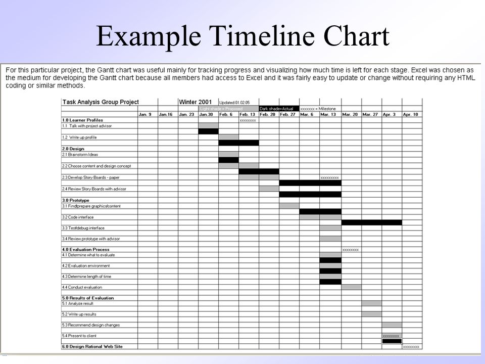
558
Methods for Tracking the Schedule
Qualitative approaches Conduct periodic project status meetings in which each team member reports progress and problems Evaluate the results of all reviews conducted throughout the software engineering process Determine whether formal project milestones (i.e., diamonds) have been accomplished by the scheduled date Compare actual start date to planned start date for each project task listed in the timeline chart Meet informally with the software engineering team to obtain their subjective assessment of progress to date and problems on the horizon Quantitative approach Use earned value analysis to assess progress quantitatively “The basic rule of software status reporting can be summarized in a single phrase: No surprises.” Capers Jones 558558 558
![]()
559
Project Control and Time Boxing
The project manager applies control to administer project resources, cope with problems, and direct project staff If things are going well (i.e., schedule, budget, progress, milestones) then control should be light When problems occur, the project manager must apply tight control to reconcile the problems as quickly as possible. For example: Staff may be redeployed The project schedule may be redefined Severe deadline pressure may require the use of time boxing An incremental software process is applied to the project The tasks associated with each increment are “time-boxed” (i.e., given a specific start and stop time) by working backward from the delivery date The project is not allowed to get “stuck” on a task When the work on a task hits the stop time of its box, then work ceases on that task and the next task begins This approach succeeds based on the premise that when the time-box boundary is encountered, it is likely that 90% of the work is complete The remaining 10% of the work can be Delayed until the next increment Completed later if required 559559 559
 then control should be light. When problems occur, the project manager must apply tight control to reconcile the problems as quickly as possible. For example: Staff may be redeployed. The project schedule may be redefined. Severe deadline pressure may require the use of time boxing. An incremental software process is applied to the project. The tasks associated with each increment are time-boxed (i.e., given a specific start and stop time) by working backward from the delivery date. The project is not allowed to get stuck on a task. When the work on a task hits the stop time of its box, then work ceases on that task and the next task begins. This approach succeeds based on the premise that when the time-box boundary is encountered, it is likely that 90% of the work is complete. The remaining 10% of the work can be. Delayed until the next increment. Completed later if required")
560
Milestones for OO Projects
Task parallelism in object-oriented projects makes project tracking more difficult to do than non-OO projects because a number of different activities can be happening at once Sample milestones Object-oriented analysis completed Object-oriented design completed Object-oriented coding completed Object-oriented testing completed Because the object-oriented process is an iterative process, each of these milestones may be revisited as different increments are delivered to the customer 560560 560

561
Earned Value Analysis 561

562
Description of Earned Value Analysis
Earned value analysis is a measure of progress by assessing the percent of completeness for a project It gives accurate and reliable readings of performance very early into a project It provides a common value scale (i.e., time) for every project task, regardless of the type of work being performed The total hours to do the whole project are estimated, and every task is given an earned value based on its estimated percentage of the total 562562 562
 for every project task, regardless of the type of work being performed. The total hours to do the whole project are estimated, and every task is given an earned value based on its estimated percentage of the total")
563
Determining Earned Value
Compute the budgeted cost of work scheduled (BCWS) for each work task i in the schedule The BCWS is the effort planned; work is estimated in person-hours or person- days for each task To determine progress at a given point along the project schedule, the value of BCWS is the sum of the BCWSi values of all the work tasks that should have been completed by that point of time in the project schedule Sum up the BCWS values for all work tasks to derive the budget at completion (BAC) Compute the value for the budgeted cost of work performed (BCWP) BCWP is the sum of the BCWS values for all work tasks that have actually been completed by a point of time on the project schedule 563563 563
 for each work task i in the schedule. The BCWS is the effort planned; work is estimated in person-hours or person- days for each task. To determine progress at a given point along the project schedule, the value of BCWS is the sum of the BCWSi values of all the work tasks that should have been completed by that point of time in the project schedule. Sum up the BCWS values for all work tasks to derive the budget at completion (BAC) Compute the value for the budgeted cost of work performed (BCWP) BCWP is the sum of the BCWS values for all work tasks that have actually been completed by a point of time on the project schedule")
564
Progress Indicators provided through Earned Value Analysis
SPI = BCWP/BCWS Schedule performance index (SPI) is an indication of the efficiency with which the project is utilizing scheduled resources SPI close to 1.0 indicates efficient execution of the project schedule SV = BCWP – BCWS Schedule variance (SV) is an absolute indication of variance from the planned schedule PSFC = BCWS/BAC Percent scheduled for completion (PSFC) provides an indication of the percentage of work that should have been completed by time t PC = BCWP/BAC Percent complete (PC) provides a quantitative indication of the percent of work that has been completed at a given point in time t ACWP = sum of BCWP as of time t Actual cost of work performed (ASWP) includes all tasks that have been completed by a point in time t on the project schedule CPI = BCWP/ACWP A cost performance index (CPI) close to 1.0 provides a strong indication that the project is within its defined budget CV = BCWP – ACWP The cost variance is an absolute indication of cost savings (against planned costs) or shortfall at a particular stage of a project 564564 564
 is an indication of the efficiency with which the project is utilizing scheduled resources. SPI close to 1.0 indicates efficient execution of the project schedule. SV = BCWP – BCWS. Schedule variance (SV) is an absolute indication of variance from the planned schedule. PSFC = BCWS/BAC. Percent scheduled for completion (PSFC) provides an indication of the percentage of work that should have been completed by time t. PC = BCWP/BAC. Percent complete (PC) provides a quantitative indication of the percent of work that has been completed at a given point in time t. ACWP = sum of BCWP as of time t. Actual cost of work performed (ASWP) includes all tasks that have been completed by a point in time t on the project schedule. CPI = BCWP/ACWP. A cost performance index (CPI) close to 1.0 provides a strong indication that the project is within its defined budget. CV = BCWP – ACWP. The cost variance is an absolute indication of cost savings (against planned costs) or shortfall at a particular stage of a project 564.")
565
Chapter 25 Risk Management
Introduction Risk identification Risk projection (estimation) Risk mitigation, monitoring, and management (Source: Pressman, R. Software Engineering: A Practitioner’s Approach. McGraw-Hill, 2005)
 Risk mitigation, monitoring, and management. (Source: Pressman, R. Software Engineering: A Practitioner’s Approach. McGraw-Hill, 2005)")
566
Introduction

567
Definition of Risk A risk is a potential problem – it might happen and it might not Conceptual definition of risk Risk concerns future happenings Risk involves change in mind, opinion, actions, places, etc. Risk involves choice and the uncertainty that choice entails Two characteristics of risk Uncertainty – the risk may or may not happen, that is, there are no 100% risks (those, instead, are called constraints) Loss – the risk becomes a reality and unwanted consequences or losses occur 567
 Loss – the risk becomes a reality and unwanted consequences or losses occur")
568
Risk Categorization – Approach #1
Project risks They threaten the project plan If they become real, it is likely that the project schedule will slip and that costs will increase Technical risks They threaten the quality and timeliness of the software to be produced If they become real, implementation may become difficult or impossible Business risks They threaten the viability of the software to be built If they become real, they jeopardize the project or the product (More on next slide) 568
 568.")
569
Risk Categorization – Approach #1 (continued)
Sub-categories of Business risks Market risk – building an excellent product or system that no one really wants Strategic risk – building a product that no longer fits into the overall business strategy for the company Sales risk – building a product that the sales force doesn't understand how to sell Management risk – losing the support of senior management due to a change in focus or a change in people Budget risk – losing budgetary or personnel commitment 569

570
Risk Categorization – Approach #2
Known risks Those risks that can be uncovered after careful evaluation of the project plan, the business and technical environment in which the project is being developed, and other reliable information sources (e.g., unrealistic delivery date) Predictable risks Those risks that are extrapolated from past project experience (e.g., past turnover) Unpredictable risks Those risks that can and do occur, but are extremely difficult to identify in advance 570
 Predictable risks. Those risks that are extrapolated from past project experience (e.g., past turnover) Unpredictable risks. Those risks that can and do occur, but are extremely difficult to identify in advance")
571
Reactive vs. Proactive Risk Strategies
Reactive risk strategies "Don't worry, I'll think of something" The majority of software teams and managers rely on this approach Nothing is done about risks until something goes wrong The team then flies into action in an attempt to correct the problem rapidly (fire fighting) Crisis management is the choice of management techniques Proactive risk strategies Steps for risk management are followed (see next slide) Primary objective is to avoid risk and to have a contingency plan in place to handle unavoidable risks in a controlled and effective manner 571
 Crisis management is the choice of management techniques. Proactive risk strategies. Steps for risk management are followed (see next slide) Primary objective is to avoid risk and to have a contingency plan in place to handle unavoidable risks in a controlled and effective manner")
572
Steps for Risk Management
Identify possible risks; recognize what can go wrong Analyze each risk to estimate the probability that it will occur and the impact (i.e., damage) that it will do if it does occur Rank the risks by probability and impact - Impact may be negligible, marginal, critical, and catastrophic Develop a contingency plan to manage those risks having high probability and high impact 572
 that it will do if it does occur. Rank the risks by probability and impact - Impact may be negligible, marginal, critical, and catastrophic. Develop a contingency plan to manage those risks having high probability and high impact")
573
Risk Identification

574
Background Risk identification is a systematic attempt to specify threats to the project plan By identifying known and predictable risks, the project manager takes a first step toward avoiding them when possible and controlling them when necessary Generic risks Risks that are a potential threat to every software project Product-specific risks Risks that can be identified only by those a with a clear understanding of the technology, the people, and the environment that is specific to the software that is to be built This requires examination of the project plan and the statement of scope "What special characteristics of this product may threaten our project plan?" 574

575
Risk Item Checklist Used as one way to identify risks
Focuses on known and predictable risks in specific subcategories (see next slide) Can be organized in several ways A list of characteristics relevant to each risk subcategory Questionnaire that leads to an estimate on the impact of each risk A list containing a set of risk component and drivers and their probability of occurrence 575
 Can be organized in several ways. A list of characteristics relevant to each risk subcategory. Questionnaire that leads to an estimate on the impact of each risk. A list containing a set of risk component and drivers and their probability of occurrence")
576
Known and Predictable Risk Categories
Product size – risks associated with overall size of the software to be built Business impact – risks associated with constraints imposed by management or the marketplace Customer characteristics – risks associated with sophistication of the customer and the developer's ability to communicate with the customer in a timely manner Process definition – risks associated with the degree to which the software process has been defined and is followed Development environment – risks associated with availability and quality of the tools to be used to build the project Technology to be built – risks associated with complexity of the system to be built and the "newness" of the technology in the system Staff size and experience – risks associated with overall technical and project experience of the software engineers who will do the work 576

577
Questionnaire on Project Risk
(Questions are ordered by their relative importance to project success) Have top software and customer managers formally committed to support the project? Are end-users enthusiastically committed to the project and the system/product to be built? Are requirements fully understood by the software engineering team and its customers? Have customers been involved fully in the definition of requirements? Do end-users have realistic expectations? Is the project scope stable? 577 (More on next slide)
 Have top software and customer managers formally committed to support the project Are end-users enthusiastically committed to the project and the system/product to be built Are requirements fully understood by the software engineering team and its customers Have customers been involved fully in the definition of requirements Do end-users have realistic expectations Is the project scope stable 577. (More on next slide)")
578
Questionnaire on Project Risk (continued)
Does the software engineering team have the right mix of skills? Are project requirements stable? Does the project team have experience with the technology to be implemented? Is the number of people on the project team adequate to do the job? Do all customer/user constituencies agree on the importance of the project and on the requirements for the system/product to be built? 578

579
Risk Components and Drivers
The project manager identifies the risk drivers that affect the following risk components Performance risk - the degree of uncertainty that the product will meet its requirements and be fit for its intended use Cost risk - the degree of uncertainty that the project budget will be maintained Support risk - the degree of uncertainty that the resultant software will be easy to correct, adapt, and enhance Schedule risk - the degree of uncertainty that the project schedule will be maintained and that the product will be delivered on time The impact of each risk driver on the risk component is divided into one of four impact levels Negligible, marginal, critical, and catastrophic Risk drivers can be assessed as impossible, improbable, probable, and frequent 579

580
Risk Projection (Estimation)
")
581
Background Risk projection (or estimation) attempts to rate each risk in two ways The probability that the risk is real The consequence of the problems associated with the risk, should it occur The project planner, managers, and technical staff perform four risk projection steps (see next slide) The intent of these steps is to consider risks in a manner that leads to prioritization Be prioritizing risks, the software team can allocate limited resources where they will have the most impact 581
 The intent of these steps is to consider risks in a manner that leads to prioritization. Be prioritizing risks, the software team can allocate limited resources where they will have the most impact")
582
Risk Projection/Estimation Steps
Establish a scale that reflects the perceived likelihood of a risk (e.g., 1-low, 10-high) Delineate the consequences of the risk Estimate the impact of the risk on the project and product Note the overall accuracy of the risk projection so that there will be no misunderstandings 582
 Delineate the consequences of the risk. Estimate the impact of the risk on the project and product. Note the overall accuracy of the risk projection so that there will be no misunderstandings")
583
Contents of a Risk Table
A risk table provides a project manager with a simple technique for risk projection It consists of five columns Risk Summary – short description of the risk Risk Category – one of seven risk categories (slide 12) Probability – estimation of risk occurrence based on group input Impact – (1) catastrophic (2) critical (3) marginal (4) negligible RMMM – Pointer to a paragraph in the Risk Mitigation, Monitoring, and Management Plan Risk Summary Risk Category Probability Impact (1-4) RMMM 583 (More on next slide)
 Probability – estimation of risk occurrence based on group input. Impact – (1) catastrophic (2) critical (3) marginal (4) negligible. RMMM – Pointer to a paragraph in the Risk Mitigation, Monitoring, and Management Plan. Risk Summary. Risk Category. Probability. Impact (1-4) RMMM (More on next slide)")
584
Developing a Risk Table
List all risks in the first column (by way of the help of the risk item checklists) Mark the category of each risk Estimate the probability of each risk occurring Assess the impact of each risk based on an averaging of the four risk components to determine an overall impact value (See next slide) Sort the rows by probability and impact in descending order Draw a horizontal cutoff line in the table that indicates the risks that will be given further attention 584
 Mark the category of each risk. Estimate the probability of each risk occurring. Assess the impact of each risk based on an averaging of the four risk components to determine an overall impact value (See next slide) Sort the rows by probability and impact in descending order. Draw a horizontal cutoff line in the table that indicates the risks that will be given further attention")
585
Assessing Risk Impact Three factors affect the consequences that are likely if a risk does occur Its nature – This indicates the problems that are likely if the risk occurs Its scope – This combines the severity of the risk (how serious was it) with its overall distribution (how much was affected) Its timing – This considers when and for how long the impact will be felt The overall risk exposure formula is RE = P x C P = the probability of occurrence for a risk C = the cost to the project should the risk actually occur Example P = 80% probability that 18 of 60 software components will have to be developed C = Total cost of developing 18 components is $25,000 RE = .80 x $25,000 = $20,000 585
 with its overall distribution (how much was affected) Its timing – This considers when and for how long the impact will be felt. The overall risk exposure formula is RE = P x C. P = the probability of occurrence for a risk. C = the cost to the project should the risk actually occur. Example. P = 80% probability that 18 of 60 software components will have to be developed. C = Total cost of developing 18 components is $25,000. RE = .80 x $25,000 = $20,")
586
Risk Mitigation, Monitoring, and Management

587
Background An effective strategy for dealing with risk must consider three issues (Note: these are not mutually exclusive) Risk mitigation (i.e., avoidance) Risk monitoring Risk management and contingency planning Risk mitigation (avoidance) is the primary strategy and is achieved through a plan Example: Risk of high staff turnover (see next slide) (More on next slide) 587
 Risk monitoring. Risk management and contingency planning. Risk mitigation (avoidance) is the primary strategy and is achieved through a plan. Example: Risk of high staff turnover (see next slide) (More on next slide) 587.")
588
Background (continued)
Strategy for Reducing Staff Turnover Meet with current staff to determine causes for turnover (e.g., poor working conditions, low pay, competitive job market) Mitigate those causes that are under our control before the project starts Once the project commences, assume turnover will occur and develop techniques to ensure continuity when people leave Organize project teams so that information about each development activity is widely dispersed Define documentation standards and establish mechanisms to ensure that documents are developed in a timely manner Conduct peer reviews of all work (so that more than one person is "up to speed") Assign a backup staff member for every critical technologist 588
 Mitigate those causes that are under our control before the project starts. Once the project commences, assume turnover will occur and develop techniques to ensure continuity when people leave. Organize project teams so that information about each development activity is widely dispersed. Define documentation standards and establish mechanisms to ensure that documents are developed in a timely manner. Conduct peer reviews of all work (so that more than one person is up to speed ) Assign a backup staff member for every critical technologist")
589
Background (continued)
During risk monitoring, the project manager monitors factors that may provide an indication of whether a risk is becoming more or less likely Risk management and contingency planning assume that mitigation efforts have failed and that the risk has become a reality RMMM steps incur additional project cost Large projects may have identified 30 – 40 risks Risk is not limited to the software project itself Risks can occur after the software has been delivered to the user (More on next slide) 589
 589.")
590
Background (continued)
Software safety and hazard analysis These are software quality assurance activities that focus on the identification and assessment of potential hazards that may affect software negatively and cause an entire system to fail If hazards can be identified early in the software process, software design features can be specified that will either eliminate or control potential hazards 590

591
The RMMM Plan The RMMM plan may be a part of the software development plan (Paragraph ) or may be a separate document Once RMMM has been documented and the project has begun, the risk mitigation, and monitoring steps begin Risk mitigation is a problem avoidance activity Risk monitoring is a project tracking activity Risk monitoring has three objectives To assess whether predicted risks do, in fact, occur To ensure that risk aversion steps defined for the risk are being properly applied To collect information that can be used for future risk analysis The findings from risk monitoring may allow the project manager to ascertain what risks caused which problems throughout the project 591

592
Seven Principles of Risk Management
Maintain a global perspective View software risks within the context of a system and the business problem that is is intended to solve Take a forward-looking view Think about risks that may arise in the future; establish contingency plans Encourage open communication Encourage all stakeholders and users to point out risks at any time Integrate risk management Integrate the consideration of risk into the software process Emphasize a continuous process of risk management Modify identified risks as more becomes known and add new risks as better insight is achieved Develop a shared product vision A shared vision by all stakeholders facilitates better risk identification and assessment Encourage teamwork when managing risk Pool the skills and experience of all stakeholders when conducting risk management activities 592

593
Summary Whenever much is riding on a software project, common sense dictates risk analysis Yet, most project managers do it informally and superficially, if at all However, the time spent in risk management results in Less upheaval during the project A greater ability to track and control a project The confidence that comes with planning for problems before they occur Risk management can absorb a significant amount of the project planning effort…but the effort is worth it 593

594
Chapter 26 Quality Management
Quality concepts Software quality assurance Software reviews Statistical software quality assurance Software reliability, availability, and safety SQA plan (Source: Pressman, R. Software Engineering: A Practitioner’s Approach. McGraw-Hill, 2005)
")
595
Quality Concepts

596
What is Quality Management
Also called software quality assurance (SQA) Serves as an umbrella activity that is applied throughout the software process Involves doing the software development correctly versus doing it over again Reduces the amount of rework, which results in lower costs and improved time to market Encompasses A software quality assurance process Specific quality assurance and quality control tasks (including formal technical reviews and a multi-tiered testing strategy) Effective software engineering practices (methods and tools) Control of all software work products and the changes made to them A procedure to ensure compliance with software development standards Measurement and reporting mechanisms 596
 Serves as an umbrella activity that is applied throughout the software process. Involves doing the software development correctly versus doing it over again. Reduces the amount of rework, which results in lower costs and improved time to market. Encompasses. A software quality assurance process. Specific quality assurance and quality control tasks (including formal technical reviews and a multi-tiered testing strategy) Effective software engineering practices (methods and tools) Control of all software work products and the changes made to them. A procedure to ensure compliance with software development standards. Measurement and reporting mechanisms")
597
Quality Defined Defined as a characteristic or attribute of something
Refers to measurable characteristics that we can compare to known standards In software it involves such measures as cyclomatic complexity, cohesion, coupling, function points, and source lines of code Includes variation control A software development organization should strive to minimize the variation between the predicted and the actual values for cost, schedule, and resources They should make sure their testing program covers a known percentage of the software from one release to another One goal is to ensure that the variance in the number of bugs is also minimized from one release to another 597

598
Quality Defined (continued)
Two kinds of quality are sought out Quality of design The characteristic that designers specify for an item This encompasses requirements, specifications, and the design of the system Quality of conformance (i.e., implementation) The degree to which the design specifications are followed during manufacturing This focuses on how well the implementation follows the design and how well the resulting system meets its requirements Quality also can be looked at in terms of user satisfaction User satisfaction = compliant product good quality delivery within budget and schedule 598
 The degree to which the design specifications are followed during manufacturing. This focuses on how well the implementation follows the design and how well the resulting system meets its requirements. Quality also can be looked at in terms of user satisfaction User satisfaction = compliant product + good quality + delivery within budget and schedule")
599
Quality Control Involves a series of inspections, reviews, and tests used throughout the software process Ensures that each work product meets the requirements placed on it Includes a feedback loop to the process that created the work product This is essential in minimizing the errors produced Combines measurement and feedback in order to adjust the process when product specifications are not met Requires all work products to have defined, measurable specifications to which practitioners may compare to the output of each process 599

600
Quality Assurance Functions
Consists of a set of auditing and reporting functions that assess the effectiveness and completeness of quality control activities Provides management personnel with data that provides insight into the quality of the products Alerts management personnel to quality problems so that they can apply the necessary resources to resolve quality issues 600

601
The Cost of Quality Includes all costs incurred in the pursuit of quality or in performing quality-related activities Is studied to Provide a baseline for the current cost of quality Identify opportunities for reducing the cost of quality Provide a normalized basis of comparison (which is usually dollars) Involves various kinds of quality costs (See next slide) Increases dramatically as the activities progress from Prevention Detection Internal failure External failure "It takes less time to do a thing right than to explain why you did it wrong." Longfellow 601
 Involves various kinds of quality costs (See next slide) Increases dramatically as the activities progress from. Prevention Detection Internal failure External failure. It takes less time to do a thing right than to explain why you did it wrong. Longfellow")
602
Kinds of Quality Costs Prevention costs Appraisal costs
Quality planning, formal technical reviews, test equipment, training Appraisal costs Inspections, equipment calibration and maintenance, testing Failure costs – subdivided into internal failure costs and external failure costs Internal failure costs Incurred when an error is detected in a product prior to shipment Include rework, repair, and failure mode analysis External failure costs Involves defects found after the product has been shipped Include complaint resolution, product return and replacement, help line support, and warranty work 602

603
Software Quality Assurance

604
Software Quality Defined
Definition: "Conformance to explicitly stated functional and performance requirements, explicitly documented development standards, and implicit characteristics that are expected of all professionally developed software" (More on next slide) 604
 604.")
605
Software Quality Defined (continued)
This definition emphasizes three points Software requirements are the foundation from which quality is measured; lack of conformance to requirements is lack of quality Specified standards define a set of development criteria that guide the manner in which software is engineered; if the criteria are not followed, lack of quality will almost surely result A set of implicit requirements often goes unmentioned; if software fails to meet implicit requirements, software quality is suspect Software quality is no longer the sole responsibility of the programmer It extends to software engineers, project managers, customers, salespeople, and the SQA group Software engineers apply solid technical methods and measures, conduct formal technical reviews, and perform well-planned software testing 605

606
The SQA Group Serves as the customer's in-house representative
Assists the software team in achieving a high-quality product Views the software from the customer's point of view Does the software adequately meet quality factors? Has software development been conducted according to pre-established standards? Have technical disciplines properly performed their roles as part of the SQA activity? Performs a set of of activities that address quality assurance planning, oversight, record keeping, analysis, and reporting (See next slide) 606
 606.")
607
SQA Activities Prepares an SQA plan for a project
Participates in the development of the project's software process description Reviews software engineering activities to verify compliance with the defined software process Audits designated software work products to verify compliance with those defined as part of the software process Ensures that deviations in software work and work products are documented and handled according to a documented procedure Records any noncompliance and reports to senior management Coordinates the control and management of change Helps to collect and analyze software metrics 607

608
Software Reviews

609
Purpose of Reviews Serve as a filter for the software process
Are applied at various points during the software process Uncover errors that can then be removed Purify the software analysis, design, coding, and testing activities Catch large classes of errors that escape the originator more than other practitioners Include the formal technical review (also called a walkthrough or inspection) Acts as the most effective SQA filter Conducted by software engineers for software engineers Effectively uncovers errors and improves software quality Has been shown to be up to 75% effective in uncovering design flaws (which constitute 50-65% of all errors in software) Require the software engineers to expend time and effort, and the organization to cover the costs 609
 Acts as the most effective SQA filter. Conducted by software engineers for software engineers. Effectively uncovers errors and improves software quality. Has been shown to be up to 75% effective in uncovering design flaws (which constitute 50-65% of all errors in software) Require the software engineers to expend time and effort, and the organization to cover the costs")
610
Formal Technical Review (FTR)
Objectives To uncover errors in function, logic, or implementation for any representation of the software To verify that the software under review meets its requirements To ensure that the software has been represented according to predefined standards To achieve software that is developed in a uniform manner To make projects more manageable Serves as a training ground for junior software engineers to observe different approaches to software analysis, design, and construction Promotes backup and continuity because a number of people become familiar with other parts of the software May sometimes be a sample-driven review Project managers must quantify those work products that are the primary targets for formal technical reviews The sample of products that are reviewed must be representative of the products as a whole 610

611
The FTR Meeting Has the following constraints
From 3-5 people should be involved Advance preparation (i.e., reading) should occur for each participant but should require no more than two hours a piece and involve only a small subset of components The duration of the meeting should be less than two hours Focuses on a specific work product (a software requirements specification, a detailed design, a source code listing) Activities before the meeting The producer informs the project manager that a work product is complete and ready for review The project manager contacts a review leader, who evaluates the product for readiness, generates copies of product materials, and distributes them to the reviewers for advance preparation Each reviewer spends one to two hours reviewing the product and making notes before the actual review meeting The review leader establishes an agenda for the review meeting and schedules the time and location (More on next slide) 611
 should occur for each participant but should require no more than two hours a piece and involve only a small subset of components. The duration of the meeting should be less than two hours. Focuses on a specific work product (a software requirements specification, a detailed design, a source code listing) Activities before the meeting. The producer informs the project manager that a work product is complete and ready for review. The project manager contacts a review leader, who evaluates the product for readiness, generates copies of product materials, and distributes them to the reviewers for advance preparation. Each reviewer spends one to two hours reviewing the product and making notes before the actual review meeting. The review leader establishes an agenda for the review meeting and schedules the time and location. (More on next slide) 611.")
612
The FTR Meeting (continued)
Activities during the meeting The meeting is attended by the review leader, all reviewers, and the producer One of the reviewers also serves as the recorder for all issues and decisions concerning the product After a brief introduction by the review leader, the producer proceeds to "walk through" the work product while reviewers ask questions and raise issues The recorder notes any valid problems or errors that are discovered; no time or effort is spent in this meeting to solve any of these problems or errors Activities at the conclusion of the meeting All attendees must decide whether to Accept the product without further modification Reject the product due to severe errors (After these errors are corrected, another review will then occur) Accept the product provisionally (Minor errors need to be corrected but no additional review is required) All attendees then complete a sign-off in which they indicate that they took part in the review and that they concur with the findings (More on next slide) 612
 Accept the product provisionally (Minor errors need to be corrected but no additional review is required) All attendees then complete a sign-off in which they indicate that they took part in the review and that they concur with the findings. (More on next slide) 612.")
613
The FTR Meeting (continued)
Activities following the meeting The recorder produces a list of review issues that Identifies problem areas within the product Serves as an action item checklist to guide the producer in making corrections The recorder includes the list in an FTR summary report This one to two-page report describes what was reviewed, who reviewed it, and what were the findings and conclusions The review leader follows up on the findings to ensure that the producer makes the requested corrections 613

614
FTR Guidelines Review the product, not the producer
Set an agenda and maintain it Limit debate and rebuttal; conduct in-depth discussions off-line Enunciate problem areas, but don't attempt to solve the problem noted Take written notes; utilize a wall board to capture comments Limit the number of participants and insist upon advance preparation Develop a checklist for each product in order to structure and focus the review Allocate resources and schedule time for FTRs Conduct meaningful training for all reviewers Review your earlier reviews to improve the overall review process 614

615
Statistical Software Quality Assurance

616
Process Steps Collect and categorize information (i.e., causes) about software defects that occur Attempt to trace each defect to its underlying cause (e.g., nonconformance to specifications, design error, violation of standards, poor communication with the customer) Using the Pareto principle (80% of defects can be traced to 20% of all causes), isolate the 20% 616
 Using the Pareto principle (80% of defects can be traced to 20% of all causes), isolate the 20% 616.")
617
A Sample of Possible Causes for Defects
Incomplete or erroneous specifications Misinterpretation of customer communication Intentional deviation from specifications Violation of programming standards Errors in data representation Inconsistent component interface Errors in design logic Incomplete or erroneous testing Inaccurate or incomplete documentation Errors in programming language translation of design Ambiguous or inconsistent human/computer interface 617

618
Six Sigma Popularized by Motorola in the 1980s
Is the most widely used strategy for statistical quality assurance Uses data and statistical analysis to measure and improve a company's operational performance Identifies and eliminates defects in manufacturing and service-related processes The "Six Sigma" refers to six standard deviations (3.4 defects per a million occurrences) (More on next slide) 618
 (More on next slide) 618.")
619
Six Sigma (continued) Three core steps
Define customer requirements, deliverables, and project goals via well-defined methods of customer communication Measure the existing process and its output to determine current quality performance (collect defect metrics) Analyze defect metrics and determine the vital few causes (the 20%) Two additional steps are added for existing processes (and can be done in parallel) Improve the process by eliminating the root causes of defects Control the process to ensure that future work does not reintroduce the causes of defects 619
 Analyze defect metrics and determine the vital few causes (the 20%) Two additional steps are added for existing processes (and can be done in parallel) Improve the process by eliminating the root causes of defects. Control the process to ensure that future work does not reintroduce the causes of defects")
620
Six Sigma (continued) All of these steps need to be performed so that you can manage the process to accomplish something You cannot effectively manage and improve a process until you first do these steps (in this order): Manage and improve the work process Control the work process Analyze the work process Measure the work process Define the work process The work to be done 620
: Manage and improve the work process. Control the work process. Analyze the work process. Measure the work process. Define the work process. The work to be done")
621
Software Reliability, Availability, and Safety

622
Reliability and Availability
Software failure Defined: Nonconformance to software requirements Given a set of valid requirements, all software failures can be traced to design or implementation problems (i.e., nothing wears out like it does in hardware) Software reliability Defined: The probability of failure-free operation of a software application in a specified environment for a specified time Estimated using historical and development data A simple measure is MTBF = MTTF + MTTR = Uptime + Downtime Example: MTBF = 68 days + 3 days = 71 days Failures per 100 days = (1/71) * 100 = 1.4 Software availability Defined: The probability that a software application is operating according to requirements at a given point in time Availability = [MTTF/ (MTTF + MTTR)] * 100% Avail. = [68 days / (68 days + 3 days)] * 100 % = 96% 622
 Software reliability. Defined: The probability of failure-free operation of a software application in a specified environment for a specified time. Estimated using historical and development data. A simple measure is MTBF = MTTF + MTTR = Uptime + Downtime. Example: MTBF = 68 days + 3 days = 71 days. Failures per 100 days = (1/71) * 100 = 1.4. Software availability. Defined: The probability that a software application is operating according to requirements at a given point in time. Availability = [MTTF/ (MTTF + MTTR)] * 100% Avail. = [68 days / (68 days + 3 days)] * 100 % = 96% 622.")
623
Software Safety Focuses on identification and assessment of potential hazards to software operation It differs from software reliability Software reliability uses statistical analysis to determine the likelihood that a software failure will occur; however, the failure may not necessarily result in a hazard or mishap Software safety examines the ways in which failures result in conditions that can lead to a hazard or mishap; it identifies faults that may lead to failures Software failures are evaluated in the context of an entire computer-based system and its environment through the process of fault tree analysis or hazard analysis 623

624
SQA Plan

625
Purpose and Layout Provides a road map for instituting software quality assurance in an organization Developed by the SQA group to serve as a template for SQA activities that are instituted for each software project in an organization Structured as follows: The purpose and scope of the plan A description of all software engineering work products that fall within the purview of SQA All applicable standards and practices that are applied during the software process SQA actions and tasks (including reviews and audits) and their placement throughout the software process The tools and methods that support SQA actions and tasks Methods for assembling, safeguarding, and maintaining all SQA-related records Organizational roles and responsibilities relative to product quality 625
 and their placement throughout the software process. The tools and methods that support SQA actions and tasks. Methods for assembling, safeguarding, and maintaining all SQA-related records. Organizational roles and responsibilities relative to product quality ")
626
Chapter 27 Change Management
Introduction SCM repository The SCM process (Source: Pressman, R. Software Engineering: A Practitioner’s Approach. McGraw-Hill, 2005)
")
627
Introduction

628
What is Change Management
Also called software configuration management (SCM) It is an umbrella activity that is applied throughout the software process It's goal is to maximize productivity by minimizing mistakes caused by confusion when coordinating software development SCM identifies, organizes, and controls modifications to the software being built by a software development team SCM activities are formulated to identify change, control change, ensure that change is being properly implemented, and report changes to others who may have an interest (More on next slide) 628
 It is an umbrella activity that is applied throughout the software process. It s goal is to maximize productivity by minimizing mistakes caused by confusion when coordinating software development. SCM identifies, organizes, and controls modifications to the software being built by a software development team. SCM activities are formulated to identify change, control change, ensure that change is being properly implemented, and report changes to others who may have an interest. (More on next slide) 628.")
629
What is Change Management (continued)
SCM is initiated when the project begins and terminates when the software is taken out of operation View of SCM from various roles Project manager -> an auditing mechanism SCM manager -> a controlling, tracking, and policy making mechanism Software engineer -> a changing, building, and access control mechanism Customer -> a quality assurance and product identification mechanism 629

630
Software Configuration
The Output from the software process makes up the software configuration Computer programs (both source code files and executable files) Work products that describe the computer programs (documents targeted at both technical practitioners and users) Data (contained within the programs themselves or in external files) The major danger to a software configuration is change First Law of System Engineering: "No matter where you are in the system life cycle, the system will change, and the desire to change it will persist throughout the life cycle" 630
 Work products that describe the computer programs (documents targeted at both technical practitioners and users) Data (contained within the programs themselves or in external files) The major danger to a software configuration is change. First Law of System Engineering: No matter where you are in the system life cycle, the system will change, and the desire to change it will persist throughout the life cycle 630.")
631
Origins of Software Change
Errors detected in the software need to be corrected New business or market conditions dictate changes in product requirements or business rules New customer needs demand modifications of data produced by information systems, functionality delivered by products, or services delivered by a computer-based system Reorganization or business growth/downsizing causes changes in project priorities or software engineering team structure Budgetary or scheduling constraints cause a redefinition of the system or product 631

632
Elements of a Configuration Management System
Configuration elements A set of tools coupled with a file management (e.g., database) system that enables access to and management of each software configuration item Process elements A collection of procedures and tasks that define an effective approach to change management for all participants Construction elements A set of tools that automate the construction of software by ensuring that the proper set of valid components (i.e., the correct version) is assembled Human elements A set of tools and process features used by a software team to implement effective SCM 632
 system that enables access to and management of each software configuration item. Process elements. A collection of procedures and tasks that define an effective approach to change management for all participants. Construction elements. A set of tools that automate the construction of software by ensuring that the proper set of valid components (i.e., the correct version) is assembled. Human elements. A set of tools and process features used by a software team to implement effective SCM")
633
Have you established a baseline yet?
633

634
Baseline An SCM concept that helps practitioners to control change without seriously impeding justifiable change IEEE Definition: A specification or product that has been formally reviewed and agreed upon, and that thereafter serves as the basis for further development, and that can be changed only through formal change control procedures It is a milestone in the development of software and is marked by the delivery of one or more computer software configuration items (CSCIs) that have been approved as a consequence of a formal technical review A CSCI may be such work products as a document (as listed in MIL-STD-498), a test suite, or a software component 634
 that have been approved as a consequence of a formal technical review. A CSCI may be such work products as a document (as listed in MIL-STD-498), a test suite, or a software component")
635
Baselining Process A series of software engineering tasks produces a CSCI The CSCI is reviewed and possibly approved The approved CSCI is given a new version number and placed in a project database (i.e., software repository) A copy of the CSCI is taken from the project database and examined/modified by a software engineer The baselining of the modified CSCI goes back to Step #2 635
 A copy of the CSCI is taken from the project database and examined/modified by a software engineer. The baselining of the modified CSCI goes back to Step #")
636
The SCM Repository

637
Paper-based vs. Automated Repositories
Problems with paper-based repositories (i.e., file cabinet containing folders) Finding a configuration item when it was needed was often difficult Determining which items were changed, when and by whom was often challenging Constructing a new version of an existing program was time consuming and error prone Describing detailed or complex relationships between configuration items was virtually impossible Today's automated SCM repository It is a set of mechanisms and data structures that allow a software team to manage change in an effective manner It acts as the center for both accumulation and storage of software engineering information Software engineers use tools integrated with the repository to interact with it 637
 Finding a configuration item when it was needed was often difficult. Determining which items were changed, when and by whom was often challenging. Constructing a new version of an existing program was time consuming and error prone. Describing detailed or complex relationships between configuration items was virtually impossible. Today s automated SCM repository. It is a set of mechanisms and data structures that allow a software team to manage change in an effective manner. It acts as the center for both accumulation and storage of software engineering information. Software engineers use tools integrated with the repository to interact with it")
638
Automated SCM Repository (Functions and Tools)
Versioning Requirements tracing Functions Data integrity Information sharing Tool integration Data integration Methodology enforcement Document standardization SCM Repository Dependency tracking Configuration management Change management Audit trails (Explained on next two slides) 638
 638.")
639
Functions of an SCM Repository
Data integrity Validates entries, ensures consistency, cascades modifications Information sharing Shares information among developers and tools, manages and controls multi-user access Tool integration Establishes a data model that can be accessed by many software engineering tools, controls access to the data Data integration Allows various SCM tasks to be performed on one or more CSCIs Methodology enforcement Defines an entity-relationship model for the repository that implies a specific process model for software engineering Document standardization Defines objects in the repository to guarantee a standard approach for creation of software engineering documents 639

640
Toolset Used on a Repository
Versioning Save and retrieve all repository objects based on version number Dependency tracking and change management Track and respond to the changes in the state and relationship of all objects in the repository Requirements tracing (Forward tracing) Track the design and construction components and deliverables that result from a specific requirements specification (Backward tracing) Identify which requirement generated any given work product Configuration management Track a series of configurations representing specific project milestones or production releases Audit trails Establish information about when, why, and by whom changes are made in the repository 640
 Track the design and construction components and deliverables that result from a specific requirements specification. (Backward tracing) Identify which requirement generated any given work product. Configuration management. Track a series of configurations representing specific project milestones or production releases. Audit trails. Establish information about when, why, and by whom changes are made in the repository")
641
Summary of CM Tools http://www.daveeaton.com/scm/CMTools.html
641
642
The SCM Process

643
Primary Objectives of the SCM Process
Identify all items that collectively define the software configuration Manage changes to one or more of these items Facilitate construction of different versions of an application Ensure the software quality is maintained as the configuration evolves over time Provide information on changes that have occurred (Compare this process to the five SCM tasks) 643
 643.")
644
SCM Questions How does a software team identify the discrete elements of a software configuration? How does an organization manage the many existing versions of a program (and its documentation) in a manner that will enable change to be accommodated efficiently? How does an organization control changes before and after software is released to a customer? Who has responsibility for approving and ranking changes? How can we ensure that changes have been made properly? What mechanism is used to appraise others of changes that are made? 644
 in a manner that will enable change to be accommodated efficiently How does an organization control changes before and after software is released to a customer Who has responsibility for approving and ranking changes How can we ensure that changes have been made properly What mechanism is used to appraise others of changes that are made 644.")
645
Configuration auditing
SCM Tasks Status reporting CSCI Identification Change control Version control Configuration auditing (More on next slide) 645
 645.")
646
SCM Tasks (continued) Concentric layers (from inner to outer)
Identification Change control Version control Configuration auditing Status reporting CSCIs flow outward through these layers during their life cycle CSCIs ultimately become part of the configuration of one or more versions of a software application or system 646

647
Identification Task Identification separately names each CSCI and then organizes it in the SCM repository using an object-oriented approach Objects start out as basic objects and are then grouped into aggregate objects Each object has a set of distinct features that identify it A name that is unambiguous to all other objects A description that contains the CSCI type, a project identifier, and change and/or version information List of resources needed by the object The object realization (i.e., the document, the file, the model, etc.) 647
 647.")
648
Change Control Task Change control is a procedural activity that ensures quality and consistency as changes are made to a configuration object A change request is submitted to a configuration control authority, which is usually a change control board (CCB) The request is evaluated for technical merit, potential side effects, overall impact on other configuration objects and system functions, and projected cost in terms of money, time, and resources An engineering change order (ECO) is issued for each approved change request Describes the change to be made, the constraints to follow, and the criteria for review and audit The baselined CSCI is obtained from the SCM repository Access control governs which software engineers have the authority to access and modify a particular configuration object Synchronization control helps to ensure that parallel changes performed by two different people don't overwrite one another 648
 The request is evaluated for technical merit, potential side effects, overall impact on other configuration objects and system functions, and projected cost in terms of money, time, and resources. An engineering change order (ECO) is issued for each approved change request. Describes the change to be made, the constraints to follow, and the criteria for review and audit. The baselined CSCI is obtained from the SCM repository. Access control governs which software engineers have the authority to access and modify a particular configuration object. Synchronization control helps to ensure that parallel changes performed by two different people don t overwrite one another")
649
Version Control Task Version control is a set of procedures and tools for managing the creation and use of multiple occurrences of objects in the SCM repository Required version control capabilities An SCM repository that stores all relevant configuration objects A version management capability that stores all versions of a configuration object (or enables any version to be constructed using differences from past versions) A make facility that enables the software engineer to collect all relevant configuration objects and construct a specific version of the software Issues tracking (bug tracking) capability that enables the team to record and track the status of all outstanding issues associated with each configuration object The SCM repository maintains a change set Serves as a collection of all changes made to a baseline configuration Used to create a specific version of the software Captures all changes to all files in the configuration along with the reason for changes and details of who made the changes and when 649
 A make facility that enables the software engineer to collect all relevant configuration objects and construct a specific version of the software. Issues tracking (bug tracking) capability that enables the team to record and track the status of all outstanding issues associated with each configuration object. The SCM repository maintains a change set. Serves as a collection of all changes made to a baseline configuration. Used to create a specific version of the software. Captures all changes to all files in the configuration along with the reason for changes and details of who made the changes and when")
650
Configuration Auditing Task
Configuration auditing is an SQA activity that helps to ensure that quality is maintained as changes are made It complements the formal technical review and is conducted by the SQA group It addresses the following questions Has the change specified in the ECO been made? Have any additional modifications been incorporated? Has a formal technical review been conducted to assess technical correctness? Has the software process been followed, and have software engineering standards been properly applied? Has the change been "highlighted" and "documented" in the CSCI? Have the change data and change author been specified? Do the attributes of the configuration object reflect the change? Have SCM procedures for noting the change, recording it, and reporting it been followed? Have all related CSCIs been properly updated? A configuration audit ensures that The correct CSCIs (by version) have been incorporated into a specific build That all documentation is up-to-date and consistent with the version that has been built 650
 have been incorporated into a specific build. That all documentation is up-to-date and consistent with the version that has been built")
651
Status Reporting Task Configuration status reporting (CSR) is also called status accounting Provides information about each change to those personnel in an organization with a need to know Answers what happened, who did it, when did it happen, and what else will be affected? Sources of entries for configuration status reporting Each time a CSCI is assigned new or updated information Each time a change is approved by the CCB and an ECO is issued Each time a configuration audit is conducted The configuration status report Placed in an on-line database or on a website for software developers and maintainers to read Given to management and practitioners to keep them appraised of important changes to the project CSCIs 651

652
Summary Introduction SCM Repository SCM Process Identification
Change control Version control Configuration auditing Status reporting 652

653
System Integration Management (SIM)
Introduction Site Architectures Sample SIM Charts (Source: Pressman, R. Software Engineering: A Practitioner’s Approach. McGraw-Hill, 2005)
")
654
Introduction

655
What is SIM? Stands for System Integration Management
Directed by the System Integrated Management Office (SIMO) in an organization Focus Implementation/Placement of new computer systems Upgrade of current computer systems Replacement of current computer systems Removal of current computer systems Goals Identify, document, and manage changes to the site architecture Plan a timely, cost-effective, and operationally focused implementation/upgrade/change/removal of computer systems Execute the transition from the baseline architecture to the objective architecture Communicate results of analysis, transition status, issues, resolution plans, and recommendations to senior management
 in an organization. Focus. Implementation/Placement of new computer systems. Upgrade of current computer systems. Replacement of current computer systems. Removal of current computer systems. Goals. Identify, document, and manage changes to the site architecture. Plan a timely, cost-effective, and operationally focused implementation/upgrade/change/removal of computer systems. Execute the transition from the baseline architecture to the objective architecture. Communicate results of analysis, transition status, issues, resolution plans, and recommendations to senior management.")
656
Site Architectures Baseline Architecture Objective Architecture
Depicts the computer hardware, software, and network connections currently installed and in use in an organization Objective Architecture Depicts the computer hardware, software, and network connections at a set point of time in the future after specific computer systems have been installed, changed, or removed in an organization

657
System Integration Management Review (SIMR)
")
658
System Integration Management Review (SIMR)
Conducted monthly by the integration contractor and overseen by the SIMO Attended by upper management, project action officers, users, operators, maintainers, and developers Presents information on status of system integration plans for operations over the next 1, 2, and 5 years

659
Site Architecture

662
System Integration Chart

664
Stoplight Chart

666
Stoplight Chart

668
Fishbone Chart

671
Radar Chart (Spiderweb Chart)
")
674
Task Network (PERT Chart version)
")
677
Timeline Chart

679
Schedule of Work

680
Quad Chart

684
ARCHITECTURE DRIVEN CONSTRUCTION AND MONITORING
Professor David C. Luckham Stanford University CONOPS Animation Complex Event Detection Event Constraint Checker Load Analysis Event Detection Network Analysis Tools C I Systems 4 Non-DoD Systems NEW IDEAS Event pattern language expressing both event causality and event timing, for rapidly configuring event filters, aggregators and constraints. Complex event processing based on event patterns, for enhancing the capabilities of existing distributed systems. Java extensions to express architecture concepts with an event-based semantics. Complex event processing and architecture conformance checking, hosted on commercial middleware. SCHEDULE Event-Based Middleware Alpha Beta Final Annotated Java for event generation Instrumented CORBA ORB Instrumented TIBCO Information BUS E-Java Instumented ORB IMPACT Instumented Bus Rapide Complex Event Processing A new highly flexible technology, hosted on all commercial middleware, for improving at runtime, the capabilities and information provided by large scale distributed systems. A new technology for scalable automated checking of conformance of distributed object systems to constraint-based industry and DOD reference architecture standards, including security standards. Design Experimented Final Event pattern language Event aggregation Event pattern constraint checker Pattern Language Event Aggregation Constraint Checker Technology Transition Alpha Beta Final Complex Event Processing hosted on Middleware. Event aggregation & constraint checking of middleware-based applications. Architecture conformance checking. Event Processing Monitoring Diagnostics Arch Conformance AO #D879 1

686
Quad Chart NEW IDEAS IMPACT SCHEDULE •
Internal Failures External Threats Situation Fault Awareness High-Level NEW IDEAS Diagnosis Reactive Control • Intelligent control methods for mode switching Fault Real-Time Distributed Mode Tolerance Selection Reconfigurable Architecture and fault tolerance in UAVs Reconfigurable Mode • Interchangeable control modules that allow for Real Time Sensor Control Switching Processing changing the mission and modes quickly • Open, distributed, plug-and-play software architecture for interoperability among heterogeneous components IMPACT SCHEDULE (2-year project) • Improved mission effectiveness for UAVs 3 6 9 12 15 18 21 24 Months: (smoother operation, improved Mid-level Coordination maneuverability and robust to failures) Fault-tolerant/Mode switching/ Reconfigurable control algorithms developed. Control algorithms integrated into software architecture. Generic control components transferred to toolkits. • Rapid response to mission or operational changes through reconfigurable software architecture for UAVs • Increased interoperability among Control Integration and Simulated Demonstration heterogeneous components Multi-level controllers Run-time infrastructure and and sensor processing Hardware-in-the-loop • Reduced development costs due to reuse of software architecture developed. modules integrated. simulation demonstrated. generic control algorithms and integration Intelligent VTOL UAV Demonstration patterns Infrastructure developed. Flight Test support developed. test.
 • Improved mission effectiveness for. UAVs Months: (smoother operation, improved. Mid-level Coordination. maneuverability and robust to failures) Fault-tolerant/Mode switching/ Reconfigurable. control algorithms. developed. Control algorithms integrated. into software architecture. Generic control components. transferred to toolkits. • Rapid response to mission or operational. changes through. reconfigurable. software. architecture for. UAVs. • Increased interoperability among. Control Integration and Simulated Demonstration. heterogeneous components. Multi-level controllers. Run-time infrastructure and. and sensor processing. Hardware-in-the-loop. • Reduced development costs due to reuse of. software architecture developed. modules integrated. simulation demonstrated. generic control algorithms and integration. Intelligent VTOL UAV Demonstration. patterns. Infrastructure developed. Flight. Test support developed. test. ")
687
Using Industry-Style Software Engineering and Project Management in a Group Project
Jay-Evan J. Tevis Department of Computer Science LeTourneau University Longview, TX

688
INTRODUCTION

689
Use of a Group Project A group project may be added as a component of a software engineering course or course sequence Its goal: Students work as a team to design and build a large software system for a real-world situation Probable result: Because of the students’ lack of real-world project experience, they will most likely handle the project as a typical programming assignment (that, in this case, lasts the whole semester)
")
690
Characteristics of a Programming Assignment Approach
Students are loosely-organized into a team They are given some general directions on the software to build They heroically attempt to build the software without any established requirements or a design They struggle to make it all look like a well-implemented and tested software application

691
Key Weaknesses of an Application Built using this Approach
Has not satisfied any baselined requirements (because none exist) Has not followed a baselined design (because none exists) Has not been adequately tested because of the lack of baselined requirements and test cases Could not be built again the same way Lack of any project planning Lack of any project tracking and oversight of the time and resources needed to accomplish the project
 Has not followed a baselined design (because none exists) Has not been adequately tested because of the lack of baselined requirements and test cases. Could not be built again the same way. Lack of any project planning. Lack of any project tracking and oversight of the time and resources needed to accomplish the project.")
692
What is a Baseline?

693
Definition of a Software Baseline
A configuration management concept that helps practitioners to control change without seriously impeding justifiable change IEEE Definition: A specification or product that has been formally reviewed and agreed upon, and that thereafter serves as the basis for further development, and that can be changed only through formal change control procedures It is a milestone in the development of software and is marked by the delivery of one or more artifacts that have been approved as a consequence of a formal technical review

694
A Different Approach for a Group Project
We use an approach that goes beyond the concepts and skills taught in a traditional computer science curriculum Our approach incorporates software engineering and software project management, and does so from an industry perspective

695
A Software Engineering Approach
Software engineering is defined as “the application of a systematic, disciplined, quantifiable approach to the development, operation, and maintenance of software; that is, the application of engineering to software” (Pressman) Software engineering requires the use of specific processes, methods, and tools with a quality focus foundation in order to develop software
 Software engineering requires the use of specific processes, methods, and tools with a quality focus foundation in order to develop software.")
696
Sample Elements of Software Engineering
Software life cycle models Requirements gathering and analysis techniques Design methodologies Standards and metrics Specifications Formal reviews Testing techniques

697
Emphasis on Key Process Areas of Project Management (SW-CMM, Level 2)
Project planning Project tracking and oversight Requirements management Configuration management Quality assurance 5 - Optimized 4 - Managed 3 - Defined 2 -Repeatable 1 - Initial

698
Objectives for Using These Practices
Take advantage of the synthesis of computer science, engineering, and project management Build a quality product that Meets user requirements Has a robust design Is adequately tested Finished on time and within budget

699
Two-Course Sequence: First Course
Software engineering process, the SW-CMM, and software life cycle models Object-oriented requirements analysis and design of a board or card game Creation of a requirements specification and a UML-based design Translation of the requirements and design into a completed software application

700
Two-Course Sequence: Second Course
Software testing techniques Group project that is six to seven weeks long Software project management Software metrics Estimation for software projects Risk management Quality management Change management

701
Overview of the Remaining Presentation
Group Project Organization The Group Project in Operation Results from Past Group Projects Conclusion and Future Work

702
GROUP PROJECT ORGANIZATION

703
Objective of the Group Project
Given a software development problem and a software development group … the student will apply software engineering and software project management principles and practices … in various assigned roles … required to complete the … Object-oriented requirements analysis Object-oriented design Construction Testing for a software product

704
Software Engineering Directorate
Organizational Structure Software Engineering Directorate Dr. Tevis Customer Liaison * Stephen Brown Joshua Millet Project Management Elijah Lofgren Requirements Management * Spenser James Aaron Cutbirth Josh Haines Jon Hersack Aaron Hume Erik Lindow Software Design * Caleb Reinking Peter Moore Daniel Patten Gary Raduns Quality Assurance * Kim White Silas Brill Brett Clark Austin Eyler Daniel Ferguson Michael Roettger Configuration Management (Contractor) C++ Software Construction * Robert Whiting Ben Cooley James Denton Brett Smith Java Software Construction * Benaiah Henry Evan Allrich Dave Estes Bill Tuscher 704
 C++ Software Construction * Robert Whiting Ben Cooley James Denton Brett Smith. Java Software Construction * Benaiah Henry Evan Allrich Dave Estes Bill Tuscher")
705
Role of Project Manager
Based on the task network, the organizational responsibilities, and the project objectives, construct an initial timeline chart for the project Maintain the timeline chart over the life of the project by getting subtask information from the team leaders and updating the status of all tasks as information becomes available Submit updated timeline charts to the Software Engineering Director before each directorate meeting and as requested Use the timeline chart to brief the current status of the project at each directorate meeting Report any project abnormalities, problems or delays to the Software Engineering Director Collect artifacts after each formal review from Requirements Management, Software Design, Software Construction, and Quality Assurance that need to be baselined Submit these artifacts to Configuration Management for baselining

706
Software Requirements Physical Configuration
Note: If formal approval does not occur following a review or audit, this will require an implied return to the previous non-review step in the process Task Network for the Organizational Software Development Process (Version 4) (SED) Discuss software needs and project scope with customer (SED) Create preliminary software development plan (SDP) (RM) Do preliminary identification of software requirements (SRS) (RM) Identify and record software requirements (SRS) (RM) Create interface requirements specification (IRS) (RM) Create OORA model (SRS) (SED) Update software development plan (SDP) Software Requirements Review (SRR) (SD) Create architectural design model (SDD) Preliminary Design Review (PDR) (QA) Create validation and system test cases (STD) (QA) Determine qualification methods for requirements (STP) (SD) Create interface design description (IDD) Test Readiness Review (TRR) (SC) Do product build and integration testing (SC) Construct source code and do unit testing Critical Design Review (CDR) (SD) Create component- level design (SDD) (QA) Do validation and system testing Test Outcome Review (TOR) (SC) Create software version description (SVD) Functional and Physical Configuration Audits (FCA/PCA) (CM) Deliver software and documentation 706
 (SED) Discuss software. needs and project scope with customer. (SED) Create preliminary software development. plan (SDP) (RM) Do preliminary identification of software. requirements (SRS) (RM) Identify and record software. requirements (SRS) (RM) Create interface requirements specification (IRS) (RM) Create OORA model (SRS) (SED) Update software. development. plan (SDP) Software Requirements. Review (SRR) (SD) Create architectural. design model (SDD) Preliminary Design. Review (PDR) (QA) Create validation and system. test cases (STD) (QA) Determine. qualification methods. for requirements (STP) (SD) Create interface design description (IDD) Test Readiness. Review (TRR) (SC) Do product build and. integration testing. (SC) Construct source code. and do unit testing. Critical Design. Review (CDR) (SD) Create component- level design (SDD) (QA) Do validation and system testing. Test Outcome. Review (TOR) (SC) Create software version description (SVD) Functional and. Physical Configuration. Audits (FCA/PCA) (CM) Deliver software and. documentation")
707
List of Formal Reviews Software Requirements Review
Preliminary Design Review Critical Design Review Test Readiness Review Test Outcome Review Functional Configuration Audit Physical Configuration Audit

708
Format for the Software Requirements and Testing Table
Req. ID Status Requirement Description Qual. Type Test Case Input Data Expected Output Actual Output Passed Test? Initial Added Changed Deleted Analysis Demonstration Inspection Test 708

709
THE GROUP PROJECT IN OPERATION

710
Software Requirements and Testing Table

711
Group Project Web Page (top half)
")
712
Group Project Web Page (bottom half)
")
713
Artifacts from the Requirements Analysis Phase (Slide 1 of 2)
Use case diagram Problem-domain class diagram System-level state diagram

714
Artifacts from the Requirements Analysis Phase (Slide 2 of 2)
Interface requirements specification

715
Artifacts from the Design Phase (Slide 1 of 2)
Design-level class diagram Identification of attributes and methods for each class

716
Artifacts from the Design Phase (Slide 2 of 2)
Interface design description

717
Artifacts from the Construction Phase
Source code files

718
Artifacts from the Testing Phase
The results from performing the test cases

719
Artifacts from the Delivery Phase (Slide 1 of 2)
Updated and detailed class diagram

720
Artifacts from the Delivery Phase (Slide 2 of 2)
Corrected source code Software version description

721
RESULTS FROM PAST GROUP PROJECTS

722
Reasons for Adapting the Group Project
Number of students enrolled in the course Lessons learned from previous projects Feedback from the students on the group project

723
Example Adaptations The course needs to be held on MWF rather than T-Th to accommodate the scheduling of the formal reviews The project needs to have a written policy on the use of laptop computers during the class meetings To create more robust teams, we assign students to a team based on student preferences and on their performance in previous computer science courses

724
The Software Engineering Director
This position is filled by the course instructor The role needs to be performed sincerely and completely as an integral part of the software development company The director should be able to Act as the moderator at class meetings and formal reviews Make decisions on the direction of the project as it occurs Approve changes in the schedule Baseline project artifacts Handle dissatisfied employees (i.e., students) in the company Reassign team leaders or members if a team fails to fulfill its responsibilities or needs help
 in the company. Reassign team leaders or members if a team fails to fulfill its responsibilities or needs help.")
725
Major Keys to Success of the Group Projects
A prescribed software process Clearly defined team roles Good organizational skills of the project manager Good performance by the team leaders

726
Example Experiences Gained by each Student
Depends on the role of each team Project manager – learned about the challenges of teams not completing their tasks on time Requirements management team – learned about the effort to gather and document user requirements Design team – learned about the chore of creating a design based on pages of user requirements Construction team – learned about the difficulties of translating a design into source code Quality assurance team – learned about the importance of well-defined and quantified requirements and well-written test cases

727
Skills that are Learned and Practiced
Communication skills by speaking in front of a group Travel skills from planning a hypothetical trip to a location for a formal review Coordination skills from working as a team and with other teams Leadership, followership, and delegation skills working as a team leader or team member Time management skills by following a timeline chart and finishing tasks on schedule Discussion skills in handling comments, questions, arguments, and compromises in a formal review

728
CONCLUSION AND FUTURE WORK

729
Summary A group project should be more than just a semester-long programming assignment It can be an opportunity for students to learn, experience, and use industry-style software engineering and software project management techniques We have described our approach for doing this Group project organization The group project in operation Results from past group projects In this group project approach, students experience some of the responsibilities, events, stress, and elation that come with project work in industry

730
Future Plans Continue incorporating
Industry processes, methods, and tools into the group project Lessons learned from students and recommendations from industry professionals Include accounting students in the next group project Provide a prediction of project costs Establish a budget Track the actual dollar costs of the software development effort as the project proceeds Bring cost data into the decision-making discussions of the project

731
ANY QUESTIONS? GROUP PROJECT WEBSITE
ANY QUESTIONS?

Similar presentations