Download presentation
Presentation is loading. Please wait.

1
Plastic Analysis of Structures By Prof. Dr. Wail Nourildean Al-Rifaie

2
Calculation of the plastic moment of resistance

4
Plastic collapse Simply supported beams: 1. The beam can thus continue to deflect at constant load due to the hinge action, and so fails by plastic collapse. 2. The load at which the collapse occurs is termed plastic collapse load and denoted Pc. 3. If P is increased steadily from zero, the beam at first behaves elastically. 4. At a certain value of the load, the central bending moment reaches the value Mp, and a plastic hinge then forms under the load. No further increase of is possible if equilibrium is to be maintained.

8
9. The mechanism method consists of the following steps: i.Identify the location of the potential plastic hinges (supports, joints, concentrated load points, and points of zero shear in portions subjected to distributed loadings). ii.Consider various combinations of these hinges to form possible collapse mechanisms. iii.Compute the loads associated with each of these possible mechanisms.
. ii.Consider various combinations of these hinges to form possible collapse mechanisms. iii.Compute the loads associated with each of these possible mechanisms..")
13
Propped Cantilever Beam 1.P increased steadily from zero, the behaviour at first wholly elastic. 2.Elastic behaviour ceases when the bending moment which is the largest occurring at any section of the beam, attain the value –Mp (for a certain value of P1 the moment at the built-in end reaches Mp) so the plastic hinge form at the end of the beam. 3.The insertion of a yield hinge at A does not transform the beam into a mechanism. 4.An additional load must be carried without further increasing the moment at A, and section B will reach Mp and a p0lastic hinge will be formed at B. 5.The collapse load will be reached when a second yield hinge develop at B.
 so the plastic hinge form at the end of the beam. 3.The insertion of a yield hinge at A does not transform the beam into a mechanism. 4.An additional load must be carried without further increasing the moment at A, and section B will reach Mp and a p0lastic hinge will be formed at B. 5.The collapse load will be reached when a second yield hinge develop at B..")
16
Fixed beam 1.“W” increased steadily from zero, the behaviour is at first wholly elastic. 2.Elastic behaviour ceases when the end bending moments which are the largest occurring at any section of the beam, attain the value –Mp, so the plastic hinges form at the ends of the beam.

19
4. If the load is increased by a small amount ∆W above W, the two plastic hinges at the ends of the beam will undergo rotation, while the bending moment at each of these hinges remains constant at the value Mp. During this process, the changes of bending moment at the ends of the beamare therefore zero. 5. Changing of the moment throughout the beam which are caused by increasing the load Wy+∆W equal to bending moments which would produced by the application of load ∆W if it were simply supported at its ends. Maximum sagging bending moment = ∆W.L/8.

20
6. From above for the fixed ended beam, the central bending moment at the yield load Wy was (1/2)Mp. Increase the load by ∆W cause this bending moment to become: (1/2)Mp + (1/8)∆W.L = Mp Hence, ∆W = 4Mp/L 7. From above, Wy = 12Mp/L Hence, the total collapse load on the beam will be : Wc = Wy + ∆W = 16Mp/L At this load a plastic hinge forms at the center of the beam.
Mp. Increase the load by ∆W cause this bending moment to become: (1/2)Mp + (1/8)∆W.L = Mp Hence, ∆W = 4Mp/L 7. From above, Wy = 12Mp/L Hence, the total collapse load on the beam will be : Wc = Wy + ∆W = 16Mp/L At this load a plastic hinge forms at the center of the beam..")
21
Propped cantilever under point loads

22
Assumptions for collapse mechanism: 1 st. assumption

23
2 nd. assumption

24
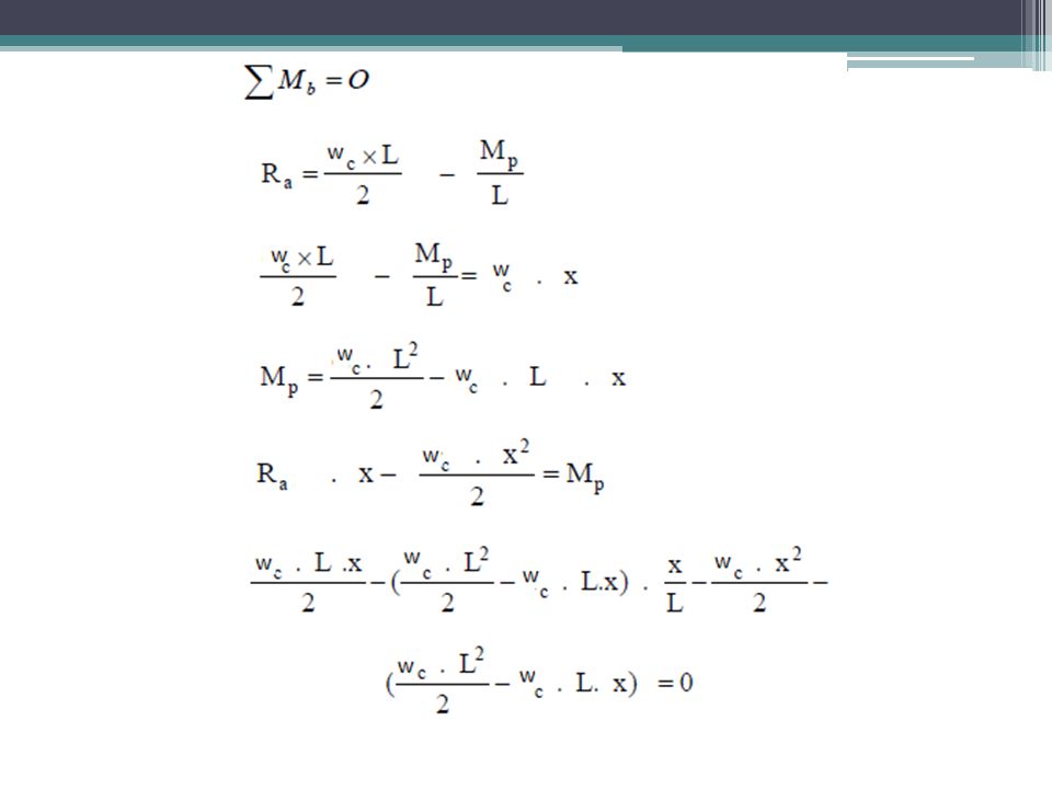
Propped cantilever under uniformly distributed load

27
The effect of fixing the ends of a portion of a beam Consider a beam of uniform section supported on four supports as shown in the figure.

28
1.The beam is subjected to a concentrated load acting at the center of the beam of overall length “L” and with a length “kL” for the end spans. “k” is a coefficient. 2.If k = 0, then the central span becomes fixed at the ends. 3.If k = ∞, the central span can be assumed to be simply supported. 4.The collapse mechanism forms as shown in the following figure.

30
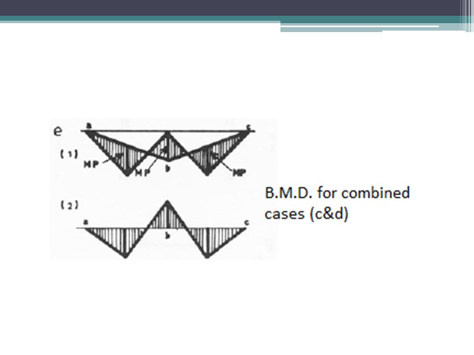
5. The collapse load can be obtained by applying the principle of virtual work, External work = Internal work Wc.(L/2). Ɵ = Ɵ.Mp +2Ɵ.Mp + Ɵ.Mp Or Wc = 8Mp/L 6. The bending moment diagram for the collapse mechanism is shown in the following figure.
. Ɵ = Ɵ.Mp +2Ɵ.Mp + Ɵ.Mp Or Wc = 8Mp/L 6. The bending moment diagram for the collapse mechanism is shown in the following figure..")
32
Continuous beams The two span continuous beam shown is subjected to a concentrated load “P” at the center of each span.

33
1. M3 is selected as redundant force, then the total number of loads acting on the structure will be the two applied loads (P), and the redundant force (M3) shown in the figure.
, and the redundant force (M3) shown in the figure..")
37
For the two span beam, there is more than one possible collapse mechanism. 1.Locate the position of the sufficient number of possible plastic hinges needed to cause a collapse mechanism. 2.Four plastic hinges can form at points 2,3,4 and 5. 3.There will therefore be two possible collapse mechanisms as shown.

39
1.In the first case collapse can take place of span 1-3,

40
2. The collapse load for the collapse mechanism of span 3-5 is obtained as follows,

41
1.For the first possible collapse mechanism, if the angular rotation of section (1), is assumed to be (θ), the angular rotation at section (3) will also be (θ), and section (2) will have a rotation of (2θ). 2.In the second case, if the angular rotation at (3) is assumed to be equal to (θ), then the angular rotation at section )5) will be equal to (θ/2) and the rotation at section (4) will be equal to (3θ/2). 3.It may be noted that the plastic moment at section (3) for both the possible mechanisms is Mp. So the plastic hinge will always form at the section which has the least value of Mp. 4.Therefore the minimum value of the collapse load is obtained from the collapse mechanism of span 3-5 of the beam. 5.Thus, the collapse mechanism shown in © gives the correct value and the correct collapse load will be Pc = 6Mp/L. 6.The bending moment diagram for the correct collapse mechanism is shown in Fig. (d) and the magnitude of the bending moment at section (2) is M2 = 5Mp/8, which is within the assumed limit of the problem. This will gives the reason for the correct collapse mechanism shown in Fig. (c).
 is assumed to be equal to (θ), then the angular rotation at section )5) will be equal to (θ/2) and the rotation at section (4) will be equal to (3θ/2). 3.It may be noted that the plastic moment at section (3) for both the possible mechanisms is Mp. So the plastic hinge will always form at the section which has the least value of Mp. 4.Therefore the minimum value of the collapse load is obtained from the collapse mechanism of span 3-5 of the beam. 5.Thus, the collapse mechanism shown in © gives the correct value and the correct collapse load will be Pc = 6Mp/L. 6.The bending moment diagram for the correct collapse mechanism is shown in Fig. (d) and the magnitude of the bending moment at section (2) is M2 = 5Mp/8, which is within the assumed limit of the problem. This will gives the reason for the correct collapse mechanism shown in Fig. (c)..")
Similar presentations