Download presentation
Presentation is loading. Please wait.

3
Rule #1 Also known as Daryl’s words to live by.

4
Those really weird calls »Once every couple of months or so we get those really weird service calls. »The problem never happens when we’re there. For that matter, the equipment always seems to be working fine. »What should we check first? What could it possibly be? »Is the unit possessed?

5
KISSKISS eep T imple tupid

6
Start with the basics! +Assume nothing, check everything, no matter how unrelated it may seem. +Forget everything that’s been done in the past service calls. +Check low voltage connections, check line voltage connections. Check voltages. +Check pressures, cycle it on the thermostat. Cycle it on the safeties. Drop out a motor.

7
±Wiggle wires, jiggle connections and look everywhere. ±Ignore your urges, remember that the last guy did what you’re considering and look how productive that was. ±What are you looking for? Won’t know til’ ya find it. Start with the basics!

8
×This is probably not one where you’ll get to use your new nuclear powered, fully digital analog read out, voice activated microprocessor ACME 1000 meter. ×Nope, this one will be solved with a pressure gauge at best. Probably a screw driver or a pair of pliers. Start with the basics!

9
KISSKISS eep T imple tupid

10
Heat Pump Systems

13
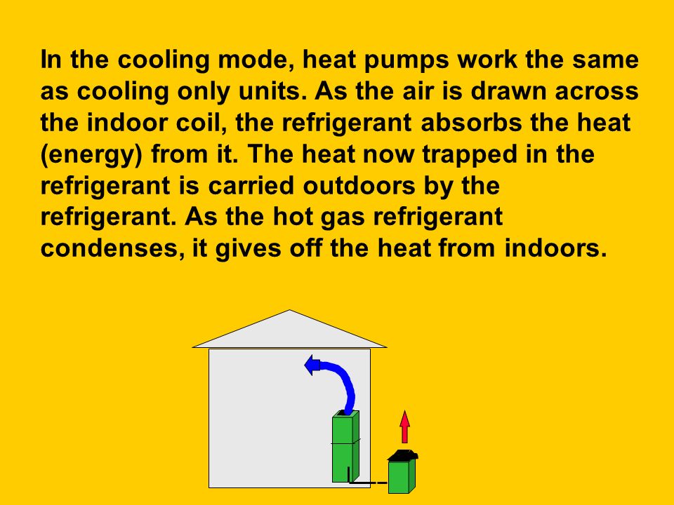
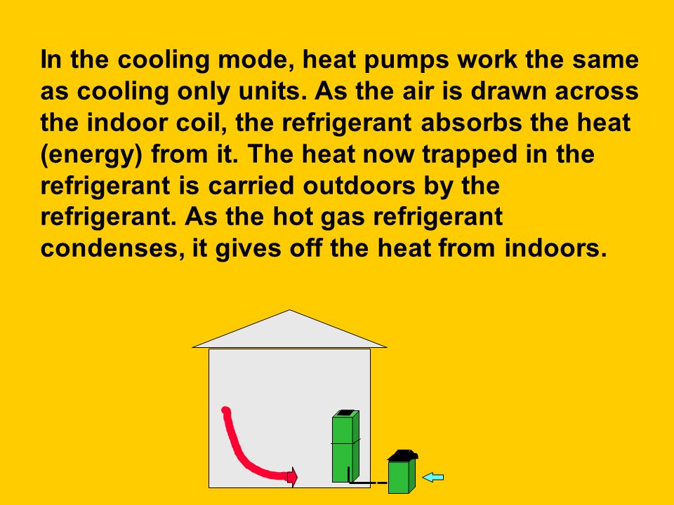
In the cooling mode, heat pumps work the same as cooling only units. As the air is drawn across the indoor coil, the refrigerant absorbs the heat (energy) from it. The heat now trapped in the refrigerant is carried outdoors by the refrigerant. As the hot gas refrigerant condenses, it gives off the heat from indoors.
 from it. The heat now trapped in the refrigerant is carried outdoors by the refrigerant. As the hot gas refrigerant condenses, it gives off the heat from indoors..")
23
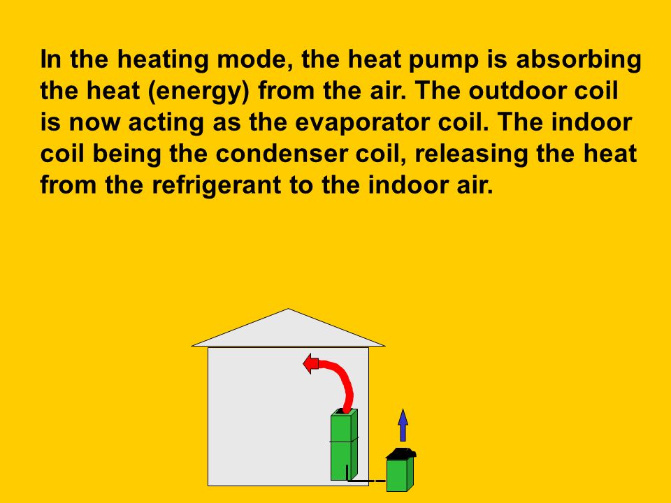
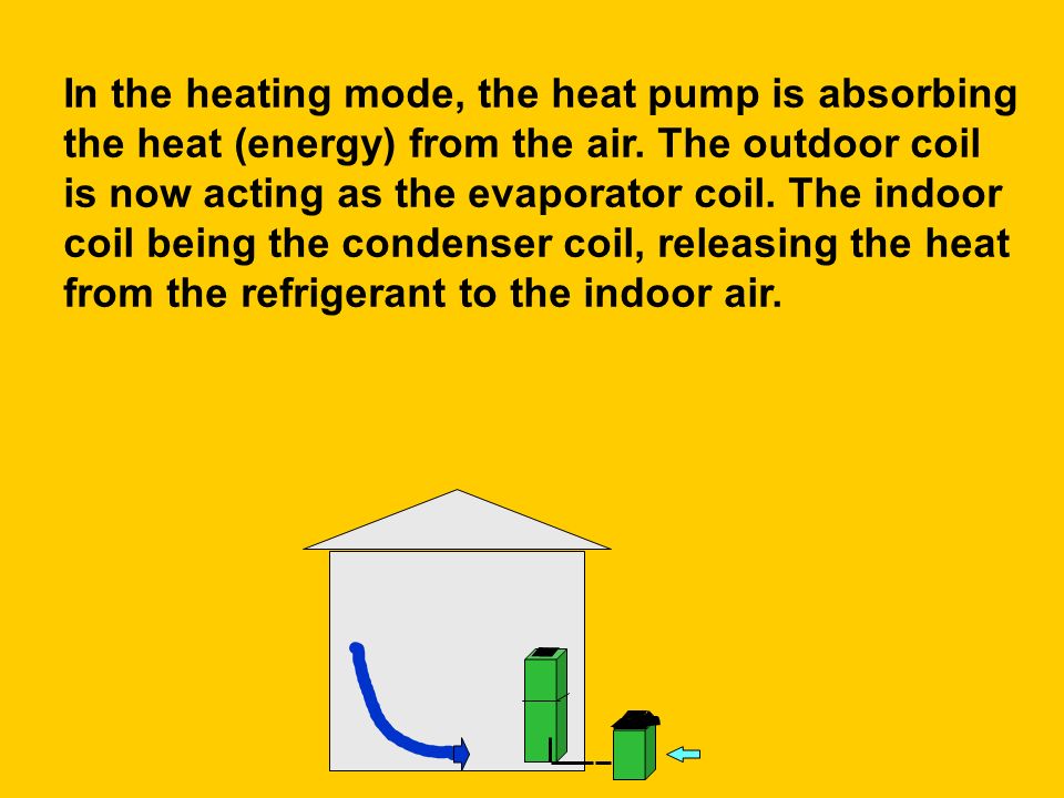
In the heating mode of operation, the refrigerant flow is reversed.

24
In the heating mode, the heat pump is absorbing the heat (energy) from the air. The outdoor coil is now acting as the evaporator coil. The indoor coil being the condenser coil, releasing the heat from the refrigerant to the indoor air.

35
Heat Pump Classification Heat pumps are classified by the medium used for heating while in the heating mode. Most residential units are air to air. Meaning they use air (the outdoor air) as their source of heat when heating. Another common type found in light commercial applications, is the water source heat pump.
 as their source of heat when heating. Another common type found in light commercial applications, is the water source heat pump..")
36
There is heat (energy) present to minus 480º F. Most current heat pumps can perform efficiently to 20º F. The need for supplemental heat will depend on the design condition and the building’s construction. The colder the outdoor ambient, the greater the heating demand is. With less heat in the outdoor air, the heat pump loses capacity. Heat Pump Classification

37
INSIDE THE HEAT PUMP COMPRESSOR CAPABLE OF OPERATING AT LOW OUTDOOR TEMPERATURES INDOOR / OUTDOOR COIL DESIGN METERING DEVICE FOR INDOOR / OUTDOOR COIL REVERSING VALVE ( 4-WAY VALVE ) ACCUMULATOR CRANKCASE HEATER AUXILIARY HEAT EMERGENCY HEAT DEFROST CYCLE
 ACCUMULATOR CRANKCASE HEATER AUXILIARY HEAT EMERGENCY HEAT DEFROST CYCLE")
38
HEAT PUMP ACCUMULATOR: –CLIMATUFF Reciprocating - PART OF COMPRESSOR SHELL –LOCATED IN SUCTION LINE BETWEEN THE COMPRESSOR AND REVERSING VALVE –WHY HAVE ONE? MOST IMPORTANT: –HEATING CYCLE - COLD TEMPERATURES, OUT DOOR COIL MAY NOT BE ABLE TO EVAPORATE ALL THE REFRIGERANT –END OF DEFROST CYCLE –LIQUID CARRYOVER WILL BE CAUGHT BY THE ACCUMULATOR TO PREVENT COMPRESSOR DAMAGE

39
To compressor From Reversing Valve Oil return orifice Liquid refrigerant Vapor refrigerant Vapor & liquid refrigerant

40
WHAT MAKES A HEAT PUMP UNIQUE SPECIAL COMPRESSOR MUCH HIGHER COMPRESSION RATIO MOST SEVERE APPLICATION HEAT PUMP COILS –ALTERNATELY FUNCTION AS EVAPORATOR AND CONDENSER –MUST TOLERATE CHARGE IMBALANCE –OUT DOOR COIL MUST BE DESIGNIED FOR EASY DEFROST

41
HEAT PUMP CRANKCASE HEATER –LOCATED ON COMPRESSOR, OLDER SYSTEMS USED COMPRESSOR WINDINGS. –RAISES TEMPERATURE OF OIL SO THAT THE ABSORPTION OF REFRIGERANT INTO THE COMPRESSOR IS KEPT TO A MINIMUM

42
THE REVERSING VALVE CONTROLS THE DIRECTION THE REFRIGERANT FLOWS HEAT PUMP

43
COOLING CONDITION INDOOR COIL SAT. SUCT. T. 41F ENT. AIR T. 76F OUTDOOR COIL SAT. COND. T. 120F ENT. AIR T. 90F 4-WAY VALVE SUCT. P. 70 PSIG SUCT. T. 52F SUPERHEAT 11F DISCHARGE PRESSURE 260 PSIG METERING DEVICE SUBCOOLING 10F COMPRESSOR

44
HEATING CONDITIONS INDOOR COIL OUTDOOR COIL SAT. COND. T. 95F ENT. AIR T. 70F SAT. SUCT. T. 20F ENT. AIR T. 45F 4-WAY VALVE DISCHARGE PRESSURE 182 PSIG METERING DEVICE SUBCOOLIN G 10F SUCT. P. 43 PSIG SUCT. T. 35F SUPERHEAT 10F COMPRESSOR

47
What to look at inside The two most important checks to perform while inside are cycle rate and fan speed/air flow. Thermostats with adjustable heat anticipation need to have it adjusted for proper operation! We had to see what air handler the system is matched up with to check our charge, to check the blower motor speed tap will only take another few minutes.

48
One of the most important steps we can do while inside the home, is briefly review normal heat pump operation with the consumer! (what to expect) Even if the consumer has had a heat pump in the past, reviewing things like demand defrost, thermostat set back, and what happens in a defrost cycle with newer equipment will make for a happier customer. What to look at inside
 Even if the consumer has had a heat pump in the past, reviewing things like demand defrost, thermostat set back, and what happens in a defrost cycle with newer equipment will make for a happier customer. What to look at inside.")
49
System air flow >The blower speed must be set for the proper operation of the outdoor section. >A system with operating pressures that will not match up to those listed on the charging chart probably has an air flow problem. >The more the refrigerant pressures match up to the charging chart, the closer the air flow is to that listed on the charging chart.

50
A system moving too much air will have a low temperature rise and possibly defrost problems. A system moving too little air will act as a mismatched application. Requiring refrigerant be removed in the fall and added in the spring. System air flow

51
±System selection should always be done with the manufacturers equipment selection guide. ±Coil capacity and air flow are critical in this selection. ±The outdoor coil should never exceed the indoor coil volume by more than a two to one ratio! System match up Not in your books

52
The indoor coil may be smaller than the outdoor coil due to operating temperatures. The indoor temperature typically no more than 74º and the larger outdoor coil will hold more refrigerant flashing off at the low outdoor ambient temperatures. System match up Not in your books

53
×If you compare these to a system operating in the cooling mode, some form of head pressure control would be needed. ×The nameplate charge on split systems is the charge used for the ARI test, and may not be right for the system you’re on. Not in your books System match up

54
¬Different match-ups will have different capacities and these may vary dramatically with outdoor design conditions. ¬Replacing only part of a system without knowing the system compatibility is taking a gamble! Not in your books System match up

55
System cycle rate =A system can be properly matched up, charged properly, the proper air flow, and no detectable problems and still not perform satisfactorily due to excessive cycling. =A system cycling excessively will not only perform poorly, but is certain to have premature failures. Not in your books

56
*The system cycle rate can be effected by the heat anticipator setting as well thermostat location. *Air drafting across the thermostat will also effect it. Air being drawn down the wall from the attic is commonly overlooked as well. System cycle rate Not in your books

57
$If you suspect air flow to be effecting the thermostat operation, cover the thermostat. $A shoebox and some masking tape work very well. For an accurate test, the cover will need to be kept in place for a couple of cycles. Not in your books System cycle rate

58
›With some after market programmable thermostats you made need to set the cycle rate to “gravity system”, for normal heat cycling. ›This can be accomplished with the heat cycle rate adjustment screws on the back of the thermostat. Not in your books System cycle rate

59
µSymptoms of excessive cycling are unusually high utility bills, premature compressor failure, and poor heating performance. µSystem cycle rate is the probably the most overlooked aspect of the system, but as critical as any other a technician can check. System cycle rate Not in your books

60
HEAT COOL F O Y X2 G T W U B R OFF RHS-1 NOR M TS SM-2 COOL HEAT RHS-2 FAN AUTO ON HA CA BL RD TSH NORM C1 H1 ODA BAYSTAT239 OR 240 HEAT PUMP THERMOSTAT

61
HEAT COOL F O Y X2 G T W U B R OFF RHS-1 NORM TS SM-2 COOL HEAT RHS-2 FAN AUTO ON HA CA BL RD TSH NORM C1 H1 ODA Fault Indication Light

63
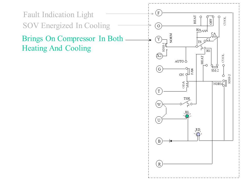
HEAT COOL F O Y X2 G T W U B R OFF RHS-1 NORM TS SM-2 COOL HEAT RHS-2 FAN AUTO ON HA CA BL RD TSH NORM C1 H1 ODA Fault Indication Light SOV Energized In Cooling Brings On Compressor In Both Heating And Cooling

64
HEAT COOL F O Y X2 G T W U B R OFF RHS-1 NORM TS SM-2 COOL HEAT RHS-2 FAN AUTO ON HA CA BL RD TSH NORM C1 H1 ODA Fault Indication Light SOV Energized In Cooling Brings On Compressor In Both Heating And Cooling Energizes Auxiliary Heat When Unit Is In Defrost

65
HEAT COOL F O Y X2 G T W U B R OFF RHS-1 NORM TS SM-2 COOL HEAT RHS-2 FAN AUTO ON HA CA BL RD TSH NORM C1 H1 ODA Fault Indication Light SOV Energized In Cooling Brings On Compressor In Both Heating And Cooling Energizes Auxiliary Heat When Unit Is In Defrost Brings On Indoor Fan

66
HEAT COOL F O Y X2 G T W U B R OFF RHS-1 NORM TS SM-2 COOL HEAT RHS-2 FAN AUTO ON HA CA BL RD TSH NORM C1 H1 ODA Fault Indication Light SOV Energized In Cooling Brings On Compressor In Both Heating And Cooling Energizes Auxiliary Heat When Unit Is In Defrost Brings On Indoor Fan Part of Heat Anticipation Circuit (Used with Trane Electro-Mechanical T’stats

67
HEAT COOL F O Y X2 G T W U B R OFF RHS-1 NORM TS SM-2 COOL HEAT RHS-2 FAN AUTO ON HA CA BL RD TSH NORM C1 H1 ODA Fault Indication Light SOV Engerized In Cooling Brings On Compressor In Both Heating And Cooling Energizes Auxiliary Heat When Unit Is In Defrost Brings On Indoor Fan Part of Heat Anticipation Circuit (Used with Trane Electro-Mechanical T’stats This Is The Second Stage-Brings On The Electric Heat

68
HEAT COOL F O Y X2 G T W U B R OFF RHS-1 NORM TS SM-2 COOL HEAT RHS-2 FAN AUTO ON HA CA BL RD TSH NORM C1 H1 ODA Fault Indication Light SOV Engerized In Cooling Brings On Compressor In Both Heating And Cooling Energizes Auxiliary Heat When Unit Is In Defrost Brings On Indoor Fan Part of Heat Anticipation Circuit (Used with Trane Electro-Mechanical T’stats This Is The Second Stage-Brings On The Electric Heat Functions As An Internal Connection For The Blue Light

69
HEAT COOL F O Y X2 G T W U B R OFF RHS-1 NORM TS SM-2 COOL HEAT RHS-2 FAN AUTO ON HA CA BL RD TSH NORM C1 H1 ODA Fault Indication Light SOV Engerized In Cooling Brings On Compressor In Both Heating And Cooling Energizes Auxiliary Heat When Unit Is In Defrost Brings On Indoor Fan Part of Heat Anticipation Circuit (Used with Trane Electro-Mechanical T’stats This Is The Second Stage-Brings On The Electric Heat Functions As An Internal Connection For The Blue Light This Is The Common Side Of The Transformer

70
This Is The Other Side Of 24 Volts From The Transformer HEAT COOL F O Y X2 G T W U B R OFF RHS-1 NORM TS SM-2 COOL HEAT RHS-2 FAN AUTO ON HA CA BL RD TSH NORM C1 H1 ODA Fault Indication Light SOV Engerized In Cooling Brings On Compressor In Both Heating And Cooling Energizes Auxiliary Heat When Unit Is In Defrost Brings On Indoor Fan Part of Heat Anticipation Circuit (Used with Trane Electro-Mechanical T’stats This Is The Second Stage-Brings On The Electric Heat Functions As An Internal Connection For The Blue Light This Is The Common Side Of The Transformer

71
HEAT COOL F O Y X2 G T W U B R OFF RHS-1 NOR M TS SM-2 COOL HEAT RHS-2 FAN AUTO ON HA CA BL RD TSH NORM C1 H1 ODA BAYSTAT239 OR 240 HEAT PUMP THERMOSTAT

72
HEAT COOL F O Y X2 G T W U B R OFF RHS-1 NORM TS SM-2 COOL HEAT RHS-2 FAN AUTO ON HA CA BL RD TSH NORM C1 H1 ODA INDOOR UNIT R B G W1

73
HEAT COOL F O Y X2 G T W U B R OFF RHS-1 NORM TS SM-2 COOL HEAT RHS-2 FAN AUTO ON HA CA BL RD TSH NORM FAN ON - ON C1 H1 ODA INDOOR UNIT R B G W1

74
HEAT COOL F O Y X2 G T W U B R OFF RHS-1 N OR M TS SM-2 COOL HEAT RHS-2 FAN AUTO ON HA CA BL RD TSH NORM C1 H1 ODA INDOOR UNIT R B G W1 BAYSTAT240A COOLING ON FAN - AUTO COOLING ON FAN - AUTO

75
HEAT COOL F O Y X2 G T W U B R OFF RHS-1 N OR M TS SM-2 COOL HEAT RHS-2 FAN AUTO ON HA CA BL RD TSH NORM C1 H1 ODA INDOOR UNIT R B G W1 BAYSTAT240A R Y X2 O BL Y O Defrost Board ODS-A R/W OUTDOOR UNIT COOLING ON FAN - AUTO

76
HEAT COOL F O Y X2 G T W U B R OFF RHS-1 NORM TS SM-2 COOL HEAT RHS-2 FAN AUTO ON HA CA BL RD TSH NORM C1 H1 HEATING - ON - FIRST STAGE FAN - AUTO ODA 15 TO 22 VOLTS (T) FROM ODS-A TO (R)
 FROM ODS-A TO (R)")
77
HEAT COOL F O Y X2 G T W U B R OFF RHS-1 N OR M TS SM-2 COOL HEAT RHS-2 FAN AUTO ON HA CA BL RD TSH NORM C1 H1 ODA INDOOR UNIT R B G W1 BAYSTAT240A

78
HEAT COOL F O Y X2 G T W U B R OFF RHS-1 N OR M TS SM-2 COOL HEAT RHS-2 FAN AUTO ON HA CA BL RD TSH NORM C1 H1 ODA R Y X2 O BL Y O Defrost Board ODS-A R/W INDOOR UNIT R B G W1 OUTDOOR UNIT BAYSTAT240A

79
HEAT COOL F O Y X2 G T W U B R OFF RHS-1 NORM TS SM-2 COOL HEAT RHS-2 FAN AUTO ON HA CA BL RD TSH NORM C1 H1 HEATING - ON - 2ND STAGE FAN - AUTO ODA 15 TO 22 VOLTS (T) FROM ODS-A TO (R)
 FROM ODS-A TO (R)")
80
HEAT COOL F O Y X2 G T W U B R OFF RHS-1 NORM TS SM-2 COOL HEAT RHS-2 FAN AUTO ON HA CA BL RD TSH NORM C1 H1 ODA 24 VOLT S (X2) FROM DEF. BRD 24 VOLT S (O) FROM DEF. BRD 15 TO 22 VOLTS (T) FROM ODS-A TO (R)
 FROM DEF. BRD 15 TO 22 VOLTS (T) FROM ODS-A TO (R).")
81
HEAT COOL F O Y X2 G T W U B R OFF RHS-1 N OR M TS SM-2 COOL HEAT RHS-2 FAN AUTO ON HA CA BL RD TSH NORM C1 H1 ODA INDOOR UNIT R B G W1 BAYSTAT240A HEATING ON EMERG. HTG (OPERATES 1.5° BELOW SETPOINT) FAN - AUTO
 FAN - AUTO.")
82
WHAT IS COOLING DROOP? Cooling droop is caused by the cooling anticipator heating up during the off cycle, causing the t’stat to come on sooner, to help overcome the thermal lag of the system. This also provides night time cooling that helps keep humidity under control

83
DROOP (cont’) Then there is Heating Droop. Heating Droop moves the temperature in the wrong direction. To compensate for this, the “T” circuit is added.

84
WHAT DOES THE “T” CIRCUIT HAVE TO DO WITH ANYTHING? The “T” circuit is a heat anticipation circuit that adds heat to the thermostat to slow down thermostat response, and removes heat to speed up the response.

85
“T” Circuit As the outdoor temperature drops, the resistance in the “T”, actually a thermistor (ODS-A), goes up. The higher the resistance, the less voltage is supplied to the resistor (ODA) located inside the thermostat. The less voltage to the ODA, the colder the t’stat thinks it is.
 located inside the thermostat. The less voltage to the ODA, the colder the t’stat thinks it is..")
86
4000.047 W 300.013 W 0°F -20°F 13.6 V 2000 9.6 V.046 W.031 W 800.036 W.069 W ODS-A.0034 A 3000 10.4 V ODS-A.0048 A 3000 14.4 V 5 V ODS-A 30°F.0063 A 3000 19 V.119 W 2.2 V ODS-A 70°F.0073 A 3000 21.8 V.159 W

87
OD Motor BR/BL 230 VOLTS R Y RD/W BK O BL Y O TT AMB. COL SENSORS T’STAT SOV F Y O R X2 B COMPR T K1 K2 DEFROST BOARD DURING DEFROST

88
WHY IS THE BLUE LIGHT ON?

89
THE BLUE LIGHT IS AN INDICATION THAT THE AUXILIARY HEAT IS ON. It is on in several instances. –If the t’stat is adjusted above set point. –If the outdoor temperature is below 40°F it will cycle off and on to maintain room temperature. If it stays on constantly above 30°F or cycles on when the outdoor temp. is above 50°F, the system should be checked.

90
The auxiliary heat light is on, but the system does not have auxiliary heat? TRANE heat pump thermostats, programmable or electro-mechanical, with this display capability (an LED) will show auxiliary heat use whenever the room temperature is a degree and a half or more below the thermostat set point. The LED is powered from the same out put from the thermostat as the heat strips, even if there are none.
 will show auxiliary heat use whenever the room temperature is a degree and a half or more below the thermostat set point. The LED is powered from the same out put from the thermostat as the heat strips, even if there are none..")
91
The heat pump can handle the load, but the customer is not comfortable? On applications with floor or side wall return registers near the floor, a small heat strip should be considered. As we get older we prefer warmer temperatures, a heat strip for just for defrost cycles can add comfort for the customer.

92
WHY IS THE RED LIGHT ON STEADY?

93
The Red Light on steady is an indication the Emergency Heat Switch is on. The switch is used only if the heat pump is inoperative, but not due to a power failure. Using the heating in this mode will increase your power consumption. The red light is to remind the customer that the temperature is being controlled by resistance heat only.

94
THE RED LIGHT ON, BUT IT IS FLASHING The Emergency Heat switch is in the Normal position.

95
RED LIGHT FLASHING If the red light is flashing, this is an indication that the defrost board has detected a defrost fault. Reset by moving the Emergency Heat Switch to the “on” position for 30 seconds. If the flashing returns, service on the heat pump may be required.

Similar presentations


/40GXC(Q) Service Training Sizes 18 and 24K.>")


