Download presentation
Presentation is loading. Please wait.

1
1 st level analysis: Design matrix, contrasts, and inference Stephane De Brito & Fiona McNabe

2
Outline What is ‘1st level analysis’? The General Linear Model and how this relates to the Design Matrix Design matrix What are we testing for? What do all the black lines mean? What do we need to include? Contrasts What are they for? t and F contrasts Inferences How do we do that in SPM5? A B C D [1 -1 -1 1]

3
Rebecca Knight Motion correction Smoothing kernel Spatial normalisation Standard template fMRI time-series Statistical Parametric Map General Linear Model Design matrix Parameter Estimates Once the image has been reconstructed, realigned, spatially normalised and smoothed…. The next step is to statistically analyse the data Overview

4
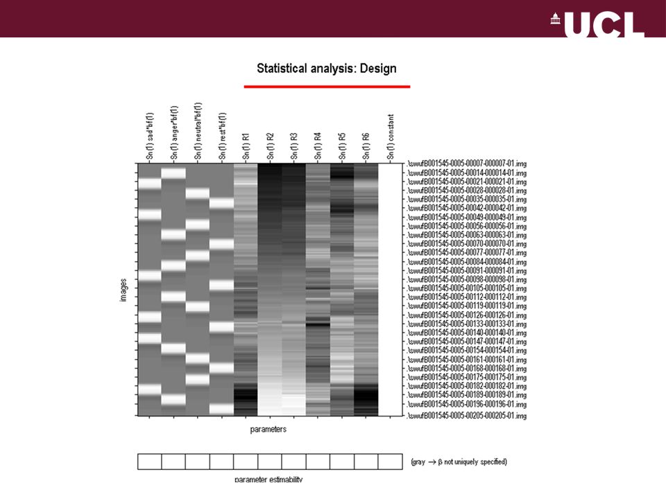
1st level analysis – A within subjects analysis where activation is averaged across scans for an individual subject The Between- subject analysis is referred to as a 2 nd level analysis and will be described later on in this course Design Matrix – The set of regressors that attempts to explain the experimental data using the GLM A dark-light colour map is used to show the value of each variable at specific time points – 2D, m = regressors, n = time. The Design Matrix forms part of the General linear model, the majority of statistics at the analysis stage use the GLM Key concepts

5
Y Generic Model Aim: To explain as much of the variance in Y by using X, and thus reducing ε Dependent Variable (What you are measuring) Independent Variable (What you are manipulating) Relative Contribution of X to the overall data (These need to be estimated) Error (The difference between the observed data and that which is predicted by the model) = X x β + ε Y = X 1 β 1 + X 2 β 2 +....X n β n.... + ε More than 1 IV ? General Linear Model

6
Y Matrix of BOLD at various time points in a single voxel (What you collect) Design matrix (This is your model specification in SPM) Parameters matrix (These need to be estimated) Error matrix (residual error for each voxel) = X x β + ε How does this equation translate to the 1 st level analysis ? Each letter is replaced by a set of matrices (2D representations) Time (rows) Voxels (columns) Time (rows) Regressors (columns)Param. weights (columns) Voxels (rows) Time (rows) Voxels GLM continued
 Time (rows) Voxels (columns) Time (rows) Regressors (columns)Param. weights (columns) Voxels (rows) Time (rows) Voxels GLM continued.")
7
Rebecca Knight Y = Matrix of Bold signals Amplitude/Intensity Time (scan every 3 seconds) fMRI brain scans Voxel time course 1 voxel = ~ 3mm³ Time ‘Y’ in the GLM Y
 fMRI brain scans Voxel time course 1 voxel = ~ 3mm³ Time ‘Y’ in the GLM Y")
8
X = Design Matrix Time (n) Regressors (m) ‘X’ in the GLM
 Regressors (m) ‘X’ in the GLM")
9
Regressors – represent hypothesised contributors to the fMRI time course in your experiment. They are represented by columns in the design matrix (1column = 1 regressor) Regressors of Interest or Experimental Regressors – represent those variables which you intentionally manipulated. The type of variable used affects how it will be represented in the design matrix (2 types: Covariates and Indicators, next slides) Regressors of no interest or nuisance regressors – represent those variables which you did not manipulate but you suspect may have an effect. By including nuisance regressors in your design matrix you decrease the amount of error. E.g. - The 6 movement regressors (rotations x3 & translations x3 ) or physiological factors e.g. heart rate, breathing or others (e.g., scanner known linear drift) Regressors
 Regressors of Interest or Experimental Regressors – represent those variables which you intentionally manipulated. The type of variable used affects how it will be represented in the design matrix (2 types: Covariates and Indicators, next slides) Regressors of no interest or nuisance regressors – represent those variables which you did not manipulate but you suspect may have an effect. By including nuisance regressors in your design matrix you decrease the amount of error. E.g. - The 6 movement regressors (rotations x3 & translations x3 ) or physiological factors e.g. heart rate, breathing or others (e.g., scanner known linear drift) Regressors.")
10
Time (n) Regressors (m) Covariates = Regressors that can take any of a continuous range of values (e.g, task difficulty) A dark-light colour map is used to show the value of each regressor within a specific time point Black = 0 and illustrates when the regressor is at its smallest value White = 1 and illustrates when the regressor is at its largest value Grey represents intermediate values The representation of each regressor column depends upon the type of variable specified Regress. of Inter. (Covariates)
.")
11
As they indicate conditions they are referred to as indicator variables Type of dummy code is used to identify the levels of each variable E.g. Two levels of one variable is on/off, represented as ON = 1 OFF = 0 When you IV is presented When you IV is absent (implicit baseline) Changes in the bold activation associated with the presentation of a stimulus Fitted Box-Car Red box plot of [0 1] doesn’t model the rise and falls Regress. of inter. (Indicators)
 Changes in the bold activation associated with the presentation of a stimulus Fitted Box-Car Red box plot of [0 1] doesn’t model the rise and falls Regress. of inter. (Indicators).")
12
E.g Movement regressors – not simply just one state or another The value can take any place along the X,Y,Z continuum for both rotations and translations Regr. of no inter. (Covariate)
.")
13
Scanner Drift Artifact and t-test E.g., Regress. of no inter.

14
Ways to improve your model: modelling haemodynamics The brain does not just switch on and off. Reshape (convolve) regressors to resemble HRF HRF basic function Original HRF Convolved More on this next week! Modelling haemodynamic
 regressors to resemble HRF HRF basic function Original HRF Convolved More on this next week. Modelling haemodynamic.")
15
The type of design and the type of variables used in your experiment will affect the construction of your design matrix Another important consideration when designing your matrix is to make sure your regressors are separate In other words, you should avoid correlations between regressors (collinear regressors) – because correlations in regressors means that variance explained by one regressor could be confused with another regressor This is illustrated by an example using a 2 x 3 factorial design Separating regressors
 – because correlations in regressors means that variance explained by one regressor could be confused with another regressor This is illustrated by an example using a 2 x 3 factorial design Separating regressors")
16
MotionNo Motion High Medium Low Design IV 1 = Movement, 2 levels (Motion and No Motion) IV 2 = Attentional Load, 3 levels (High, Medium or Low) High Medium Low Example
 IV 2 = Attentional Load, 3 levels (High, Medium or Low) High Medium Low Example")
17
V A C 1 C 2 C 3 M N h m l If you made each level of the variables a regressor you could get 5 columns and this would enable you to test main effects BUT what about interactions? How can you test differences between Mh and Nl This design matrix is flawed – regressors are correlated and therefore a presence of overlapping variance (Grey) M N h m l MNhmlMNhml Example Con’t
 M N h m l MNhmlMNhml Example Con’t.")
18
h m l h m l M M M N N N If you make each condition a regressor you create 6 columns and this would enable you to test main effects AND it enable you to test interactions! You can test differences between Mh and Nl This design matrix is orthogonal – regressors are NOT correlated and therefore each regressor explains separate variance MNMN h m l MhMh NhNh MlMlMmMm NmNm NlNl h m l h m l M M M N N N hmlhml hmlhml MMMNNNMMMNNN Orthogonal Design Matrix

19
Y Matrix of BOLD signals Design matrixMatrix parameters = X x + ε Time Voxels Time Regressors Voxels Time Voxels Error matrix β Aim: To explain as much of the variance in Y by using X, and thus reducing ε β = relative contribution that each regressor has, the larger the β value = the greater the contribution Next: Examine the effect of regressors and the contrasts Interim Summary

20
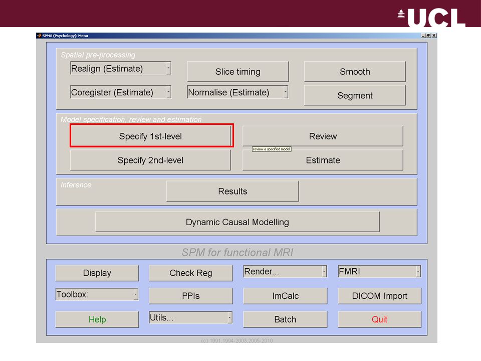
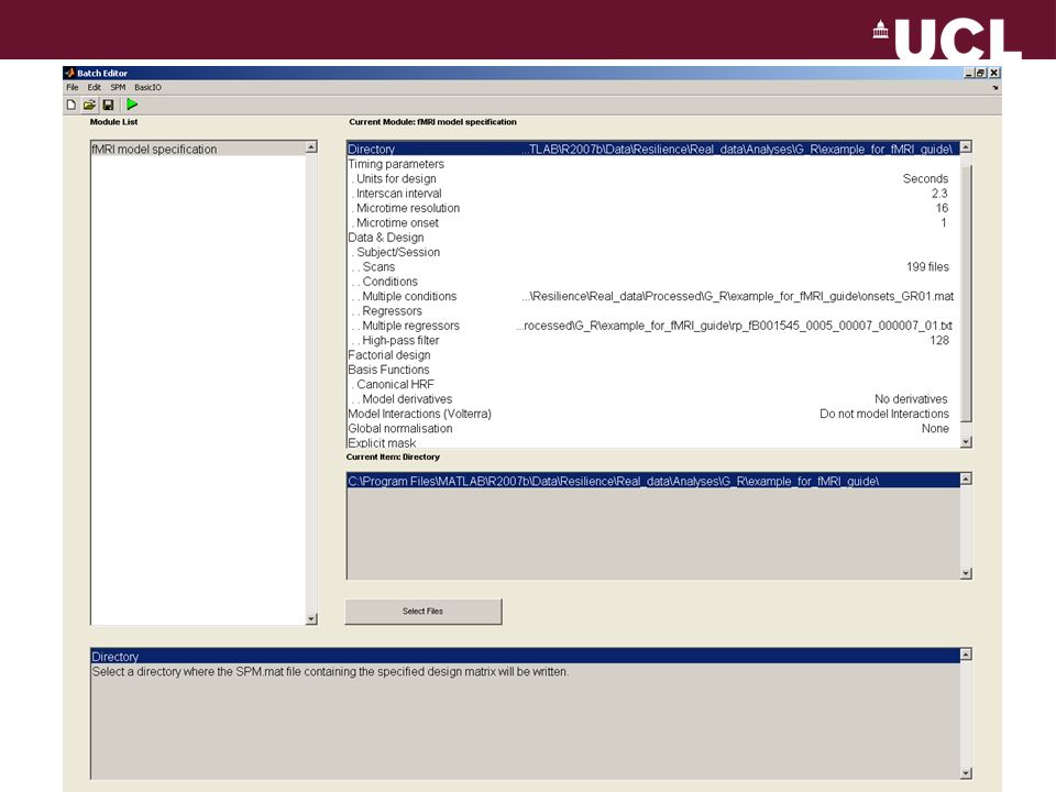
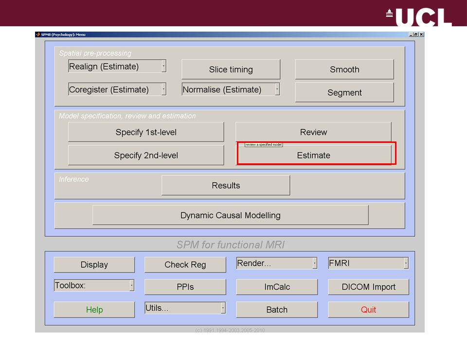
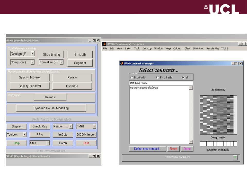
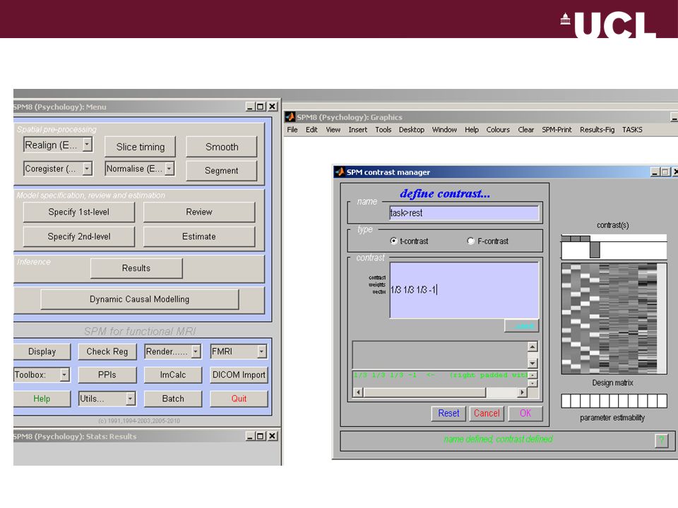
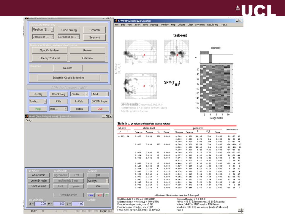
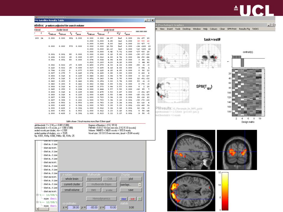
BRIEF OVERVIEW: SPECIFY THE 1 ST MODEL IN SPM

29
Thank you!

Similar presentations

 forms a basis according to which.>")


>")
 SPM Course 2010 University of Zurich, 17-19 February 2010 Klaas Enno Stephan Laboratory for Social & Neural Systems Research.>")


