Download presentation
Presentation is loading. Please wait.

1
Types of fluid flow Steady or unsteady Uniform or non-uniform Laminar and turbulent Compressible or incompressible Viscous or non-viscous Rotational or irrotational 1-D, 2-D and 3-D.

2
Eulers equation of motion This is the equation of motion in which forces due to gravity and pressure are taken into consideration. Euler’s equation along a streamline is derived by applying Newton’s second law of motion to a fluid element moving along a streamline.

3
Eulers equation of motion derivation Consider a streamline in which flow is taking place in s-direction. Consider a cylindrical element of cross section dA and length ΔS.

4
Derivation contd…. Considering gravity as the only body force component acting vertically downward (see fig.), the net external force acting on the fluid element along the directions can be written as
, the net external force acting on the fluid element along the directions can be written as.")
5
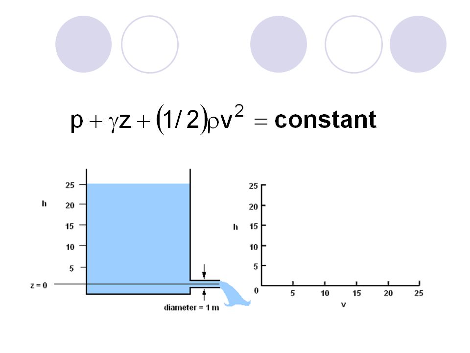
Bernoulli’s equation Assumptions Viscous effects are negligible Steady flow (time-independent) Incompressible flow Valid along a streamline Equation (think energy conservation)
 Incompressible flow Valid along a streamline Equation (think energy conservation)")
6
Bernoulli – a simple application ?? (a)(b)(c)
(b)(c)")
7
An analogous example: Holes in a soda bottle; flow from base of dam Now, how do we calaculate the velocity of the fluid as it leaves the tank? (or soda bottle)?
 .")
9
Hydraulic machines (Turbines & Pumps)
")
10
Hydraulic Machines Hydraulic machines are defined as those devices which convert either hydraulic energy into mechanical energy or mechanical into hydraulic energy.

11
Classification According to energy consideration Machines that supply energy to fluid (Pumps) An increase in pressure takes place in pumps, fans, compressors and propellers. Machines that extracts energy from fluid (Turbines) A decrease in pressure takes place in turbines.
 A decrease in pressure takes place in turbines..")
12
Classifications contd… Based on direction of flow Axial flow Radial flow Mixed flow Based on the manner of transmission of energy Kinetic displacement (Centrifugal pumps and turbines) Positive displacement (Reciprocating pumps)
 Positive displacement (Reciprocating pumps)")
13
HydraulicTurbines

14
Hydraulic Turbines are devices that convert hydraulic energy(energy possessed by water) into mechanical energy. The energy of the water can be in the form of potential or kinetic energy.

15
Turbines Classification According to the energy used Impulse turbine Reaction turbine Direction of water flow Axial flow- Radial in axial out Inward flow- Outward flow According to the head available to the inlet of turbine High Head Turbine (250-1800m), Pelton Wheel Medium Head Turbine (50-250m), Francis Turbine Low Head Turbine ( <50m), Kaplan Turbine According to the specific speed Low specific speed ( <50) Pelton wheel Medium specific speed (50 < N s < 250) Francis High Specific speed ( >250) Kaplan According to the fluid used Water Turbine (Pelton Wheel, Francis Turbine, Kaplan Turbine) Gas Turbine Steam Turbine
, Pelton Wheel Medium Head Turbine (50-250m), Francis Turbine Low Head Turbine ( <50m), Kaplan Turbine According to the specific speed Low specific speed ( <50) Pelton wheel Medium specific speed (50 < N s < 250) Francis High Specific speed ( >250) Kaplan According to the fluid used Water Turbine (Pelton Wheel, Francis Turbine, Kaplan Turbine) Gas Turbine Steam Turbine")
16
Turbines Classification (Contd…) Impulse Turbine All available head of water is converted into kinetic energy or velocity head in a nozzle. The water shoots out of the nozzle and hits a bucket which rotates a shaft. Water is in contact with atmosphere all the time and water discharged from bucket fall freely The flow is similar to open channel flow and works under atmospheric pressure. The kinetic energy of water is converted to mechanical energy. The water entering the turbine exerts a force in the direction of the flow. Pelton wheel is an example.

17
Turbines Classification (Contd…) Reaction Turbine The entire water flow takes place in closed conduit and under pressure. At the entrance to turbine/runner only part of the energy is converted to kinetic energy, remaining into pressure energy The flow is similar to the closed conduit flow. The water exerts a reaction opposite to the direction of its flow while leaving the turbine. Reaction turbines may be inward or outward or radial flow. Francis turbine, Kaplan Turbines are some example

18
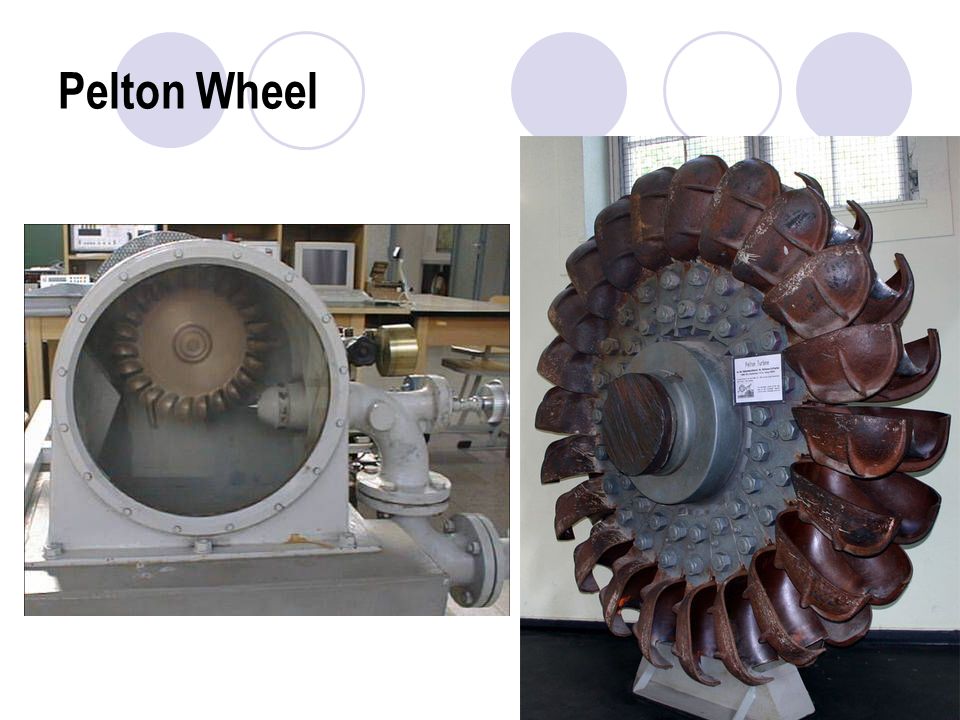
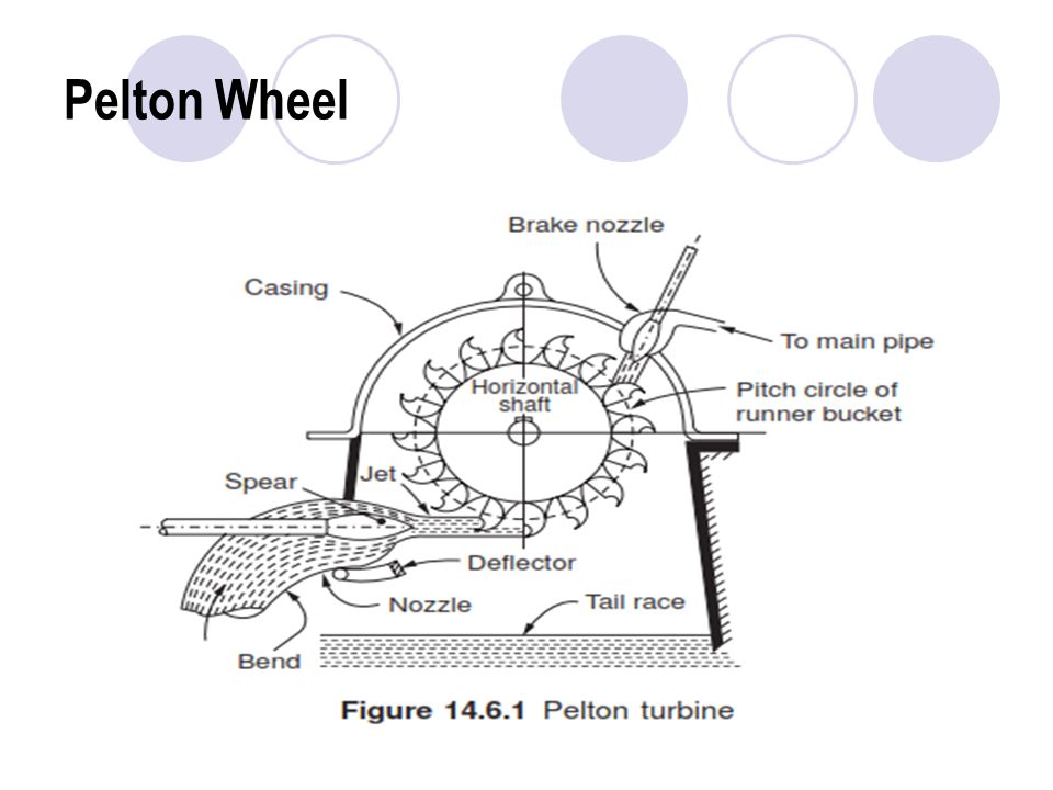
Impulse Turbine Pelton Wheel It consists of a wheel mounted on a shaft. Buckets are mounted on the periphery of the wheel Water is impinged on the buckets and energy is transferred The water has only kinetic energy Each bucket is shaped like a double hemispherical cup with a sharp edge at the center. Pelton wheel is used for high head of water (150- 2000m) The flow is tangential.
 The flow is tangential..")
19
Pelton Wheel

22
Reaction Turbine Francis Turbine The Francis turbine is a reaction turbine, which means that the working fluid changes pressure as it moves through the turbine, giving up its energy. A casement is needed to contain the water flow. The turbine is located between the high pressure water source and the low pressure water exit, usually at the base of a dam. The inlet is spiral shaped. Guide vanes direct the water tangentially to the runner. This radial flow acts on the runner vanes, causing the runner to spin. The guide vanes (or wicket gate) may be adjustable to allow efficient turbine operation for a range of water flow conditions. As the water moves through the runner its spinning radius decreases, further acting on the runner. Imagine swinging a ball on a string around in a circle. If the string is pulled short, the ball spins faster. This property, in addition to the water's pressure, helps inward flow turbines harness water energy
 may be adjustable to allow efficient turbine operation for a range of water flow conditions. As the water moves through the runner its spinning radius decreases, further acting on the runner. Imagine swinging a ball on a string around in a circle. If the string is pulled short, the ball spins faster. This property, in addition to the water s pressure, helps inward flow turbines harness water energy.")
23
Francis Turbine

24
Draft Tube The turbines have to be installed a few meters above the flood water level to avoid inundation. (In the case of impulse turbines this does not lead to significant loss of head) In the case of reaction turbines, the loss due to the installation at a higher level from the tailrace will be significant.
 In the case of reaction turbines, the loss due to the installation at a higher level from the tailrace will be significant..")
25
Draft Tube This loss is reduced by connecting a fully flowing diverging tube from the turbine outlet to be immersed in the tailrace at the tube outlet. The loss in net(effective) head is reduced by this arrangement. Also because of the diverging section of the tube the kinetic energy is converted to pressure energy which adds to the effective head.
 head is reduced by this arrangement. Also because of the diverging section of the tube the kinetic energy is converted to pressure energy which adds to the effective head..")
26
Francis Turbine

27
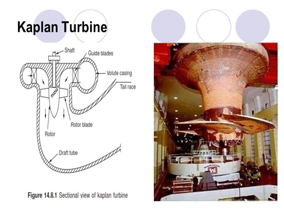
Kaplan Turbine The Kaplan turbine is a propeller-type water turbine that has adjustable blades. It is an axial flow reaction turbine Because of the adjustable blades it is possible to run at maximum efficiency at any load. Water flows through the guide vanes, and then flows axially through the runners. The runner blade angles can be changed by a lever. It can work on very low head but requires high flow rate.

28
Kaplan Turbine

30
Pumps

31
A pump is a device used to move gases, liquids or slurries. A pump moves liquids or gases from lower pressure to higher pressure, and overcomes this difference in pressure by adding energy to the system. Mechanical Energy Hydraulic energy Pumps

32
Pumps Classification

33
Pumps Classification (contd)… Pumps are divided into two fundamental types based on the manner in which they transmit energy to the pumped media: kinetic or positive displacement. In kinetic displacement, a centrifugal force of the rotating element, called an impeller, “impels” kinetic energy to the fluid, moving the fluid from pump suction to the discharge. Positive displacement uses the reciprocating action of one or several pistons, or a squeezing action of meshing gears, lobes, or other moving bodies, to displace the fluid from one area into another (i.e., moving the material from suction to discharge). Sometimes the terms ‘inlet’ (for suction) and ‘exit’ or ‘outlet’ (for discharge) are used.
. Sometimes the terms ‘inlet’ (for suction) and ‘exit’ or ‘outlet’ (for discharge) are used..")
34
Pumps Applications To deliver fluid at a higher elevation or at a long distance. To deliver fluid at a pressurized device For the control of hydraulic systems For drainage system, removing slurries, mud, water For irrigation systems Cleaning, car wash

35
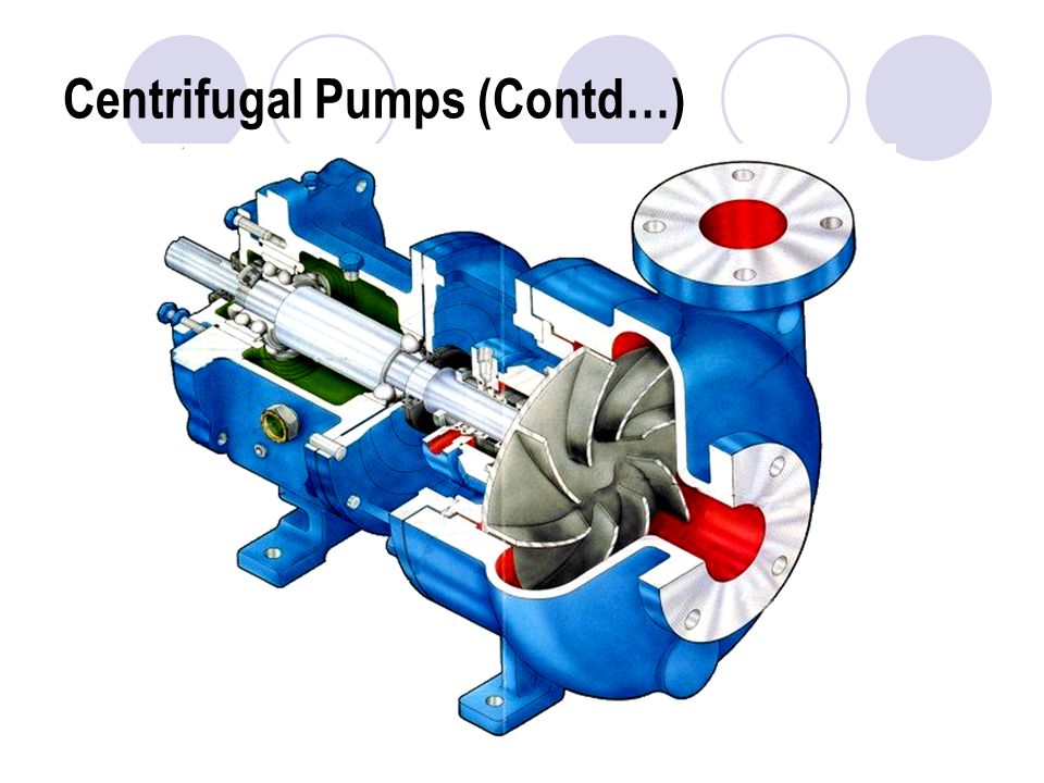
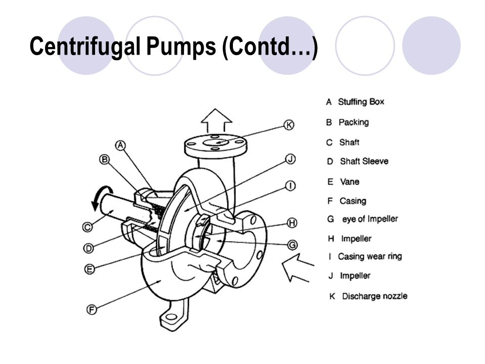
Centrifugal Pumps The hydraulic machines that converts the mechanical energy into pressure energy by means of centrifugal force acting on the fluid are called centrifugal pumps. 3 important parts are Impeller Volute casing Suction and delivery pipes.

36
Centrifugal Pumps

37
Centrifugal Pumps (Contd…) The rotating part of the centrifugal pump is called impeller. It is a rotating solid disk with curved blades. Impellers could be open, semi-open or closed. OpenSemi - OpenClosed

38
Centrifugal Pumps (Contd…) For Incompressible fluids (water) backward curved vanes are used (pumps) For compressible fluids (air) forward curved vanes are used (compressors) Backward curved Radial curvedForward curved
 For Incompressible fluids (water) backward curved vanes are used (pumps) For compressible fluids (air) forward curved vanes are used (compressors) Backward curved Radial curvedForward curved")
39
Centrifugal Pumps (Contd…) Casing is an airtight passage surrounding the impeller which converts the kinetic energy of the fluid leaving the impeller into pressure energy. Suction pipe is connected to the inlet of the pump and other side is dipped into the fluid in a sump. Delivery pipe is connected to the outlet of the pump and other end delivers the fluid at required height.

40
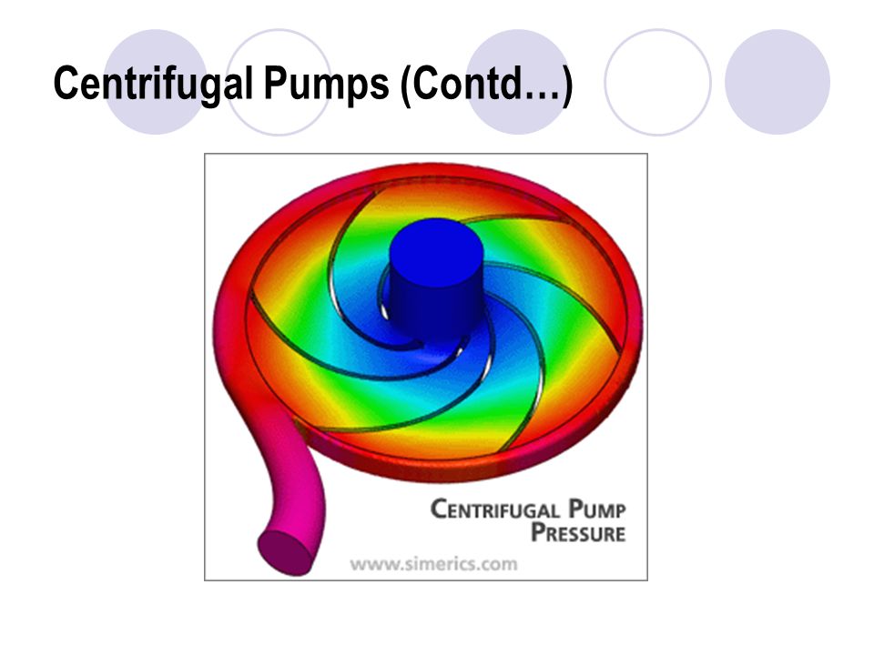
Centrifugal Pumps (Contd…) Working principle The impeller is keyed onto a shaft which is mounted on bearings and is coupled to a motor which rotates the impeller. The kinetic energy of the impeller is transmitted to the fluid and its velocity increases. The volute casing converts the kinetic energy of the fluid to pressure energy. The pressure at the center of the impeller (eye) decreases as the fluid flows outward. The decrease in pressure causes the fluid of the sump to continuously flow through the suction pipes. The high pressure fluid is delivered through the delivery pipe.
 decreases as the fluid flows outward. The decrease in pressure causes the fluid of the sump to continuously flow through the suction pipes. The high pressure fluid is delivered through the delivery pipe..")
41
Centrifugal Pumps (Contd…)
")
45
Priming The pump casing must be filled with liquid before the pump is started, or the pump will not be able to function. To ensure that a centrifugal pump remains primed most centrifugal pumps have foot valves installed or are located below the level of the source from which the pump is to take its suction.

46
Centrifugal Pumps (Contd…) Cavitations If the suction pressure at the eye of the impeller falls below the vapor pressure of the fluid being pumped, the fluid will start to boil. Any vapor bubbles formed by the pressure drop at the eye of the impeller are swept along the impeller vanes by the flow of the fluid. When the bubbles enter a region where local pressure is greater than saturation pressure farther out the impeller vane, the vapor bubbles abruptly collapse. This phenomenon is called cavitation.

47
Centrifugal Pumps (Contd…) There are several effects of cavitations It creates noise, vibration, and damage to many of the components. We experience a loss in capacity. The pump can no longer build the same head (pressure) The output pressure fluctuates. The pump's efficiency drops.
 The output pressure fluctuates. The pump s efficiency drops..")
48
Centrifugal Pumps (Contd…) Effect of cavitation
 Effect of cavitation")
49
Centrifugal Pumps (Contd…) Prevention of cavitation Raise the liquid level in the tank Lower the pumping fluid temperature Reduce the N.P.S.H. Required Use a pump with a larger, impeller eye opening. Pump should be airtight Friction losses should be decreased

50
Centrifugal Pumps (Contd…) NPSH (Net positive suction head) To avoid cavitation in centrifugal pumps, the pressure of the fluid at all points within the pump must remain above saturation pressure. The quantity used to determine if the pressure of the liquid being pumped is adequate to avoid cavitation is the net positive suction head (NPSH).
..")
51
Centrifugal Pumps (Contd…) The net positive suction head available (NPSHA) is the difference between the pressure at the suction of the pump and the saturation pressure for the liquid being pumped. The net positive suction head required (NPSHR) is the minimum net positive suction head necessary to avoid cavitation. NPSHA must be greater than NPSHR to avoid cavitation. NPSHA > NPSHR NPSHA = P suction – P saturation = P a + P st – P st - h f
 is the minimum net positive suction head necessary to avoid cavitation. NPSHA must be greater than NPSHR to avoid cavitation. NPSHA > NPSHR NPSHA = P suction – P saturation = P a + P st – P st - h f.")
52
Centrifugal Pumps (Contd…) Configuration of pumps Pumps in parallel For high flow rate requirement Head or pressure developed is same as the individual pump Flow rate is the summation of the individual pumps Pumps in series For high head or pressure requirement Flow rate remains same as the individual pump Head or pressure is the summation of two pumps.
 Configuration of pumps Pumps in parallel For high flow rate requirement Head or pressure developed is same as the individual pump Flow rate is the summation of the individual pumps Pumps in series For high head or pressure requirement Flow rate remains same as the individual pump Head or pressure is the summation of two pumps.")
53
Centrifugal Pumps (Contd…)
")
54
High velocity vs. High pressure Water can be raised from one level to a higher level in two ways – High pressure and High velocity High velocity method is very inefficient since the friction increases with proportional to the square of the velocity High pressure method is efficient because of low friction.

55
Centrifugal Pumps (Contd…) Characteristics curve Discharge, Q Efficiency and Head/Pressure Head (Pump Curve) Efficiency Fig: Characteristics curve of a centrifugal pump System curve Operating point
 Characteristics curve Discharge, Q Efficiency and Head/Pressure Head (Pump Curve) Efficiency Fig: Characteristics curve of a centrifugal pump System curve Operating point")
56
Centrifugal Pumps (Contd…) Specific Speed (N S ) It is the speed of a pump with a discharging capacity of 1 m 3 /sec and a head of 1 m. N S = n √Q / H 3/4 n = speed of the pump Q = discharge of the pump H = head of the pump Pump selection is done based on the specific speed.

57
Rotary PDP A rotary pump traps fluid in its closed casing and discharges a smooth flow. They can handle almost any liquid that does not contain hard and abrasive solids, including viscous liquids. They are also simple in design and efficient in handling flow conditions that are usually considered to low for economic application of centrifuges. Types of rotary pumps include cam-and-piston, gear, lobular, screw, and vane pumps

58
Rotary PDP External Gear Pump

59
Rotary PDP Internal Gear Pump

60
Rotary PDP Lobe Pump

61
Rotary PDP Vane Pump

62
Rotary PDP Screw Pump

63
Rotary PDP Diaphragm Pump Cross-section of a diaphragm pump

64
Rotary PDP Piston pump

Similar presentations