Download presentation
Presentation is loading. Please wait.

1
… Work in progress at CTF3 … Davide Gamba 01 July 2013 Study and Implementation of L INEAR F EEDBACK T OOLS for machine study and operation.

2
Overview Physical case: -CLIC and CTF3. -Improving drive beam recombination. Linear feedback system: – Simulations. Preliminary results: – Linac orbit corection. – Orbit “matching” in TL1. – Comparison with MADX model. – Possible other application. Summary.

3
Physical case

4
CLIC A study for a post LHC e+ e- collider. Based on high-gradient, normal conducting cavities.

5
CTF3 The CLIC Test Facility

6
CTF3 The CLIC Test Facility Prove the feasibility of the two-beam acceleration schema Test the recombination process

7
Improving drive beam recombination Only half of the beam goes through the Delay Loop. The delayed and straight beam must have the same orbit in the next Transfer Line (TL1).
..")
8
Solving a linear system of equations

9
SVD Synchronization

10
Real life constrains Data acquisition is affected by noise – White noise – Dispersion induced noise Non responsive control system – Delicate F RONT -E NDS – What you set is not necessarily what you get Instable beam – Mainly coming from RF instabilities B EAM POSITION is not a well defined measurement in case of losses Challenging machine under commissioning – MADX model not always accurate – Aperture limitations

11
Linear feedback system

12
Feedback requirements A good knowledge of the response matrix is necessary MADX Response Matrix is not accurate Algorithm to measure the response matrix needed – Has to be “fast” compared to machine faults and drifts – Has to filter noise (dispersive noise and white noise) – Beam losses must be kept low Correctors excitation has to be low – Has to be able to follow slow drifts of the machine Development Environment has to be interactive, of easy and fast integration during machine operation – Matlab is a necessary choice – An interface Matlab-Control System is necessary
 – Beam losses must be kept low Correctors excitation has to be low – Has to be able to follow slow drifts of the machine Development Environment has to be interactive, of easy and fast integration during machine operation – Matlab is a necessary choice – An interface Matlab-Control System is necessary")
13
How to measure response matrix Measure the response matrix based on a simple concept: 1.Randomly excite all the correctors 2.Read the Beam Position at all the interested points 3.Invert the same linear system of equations, but the Response Matrix is now the unknown: 4.Keep a history of last setting/observations pairs of variable length 5.Also during beam corrections outcome data can be used to improve Response Matrix.

14
Linear feedback system: GUI Developed a Matlab application for generic linear feedbacks.

15
matlabMonitor.m – Is our main interface to acquire data from CERN CO system – Works in subscription mode Good synchronization of required signals data It calls a Matlab user-defined function at each beam shot -> highly customizable – Can be used to quickly setup an acquisition process to save data to file for post-processing purpose. Each set of data related to a single shot can be stored on a single.mat file matlabSolver.m – Is a generic class to solve linear problems like the one here presented – It implements the Response Matrix improving algorithm linearFeedback.m – It requires only few lines of code to setup a generic feedback to control a list of observables, acting on a list of actuators – It doesn’t require an initial knowledge of the response matrix - First public release and documentation coming soon - Linear feedback system: libraries

16
Testing the response matrix measurement algorithm Dipoles excitation amplitude := 1 Solver history size: 60

17
Testing the response matrix measurement algorithm correctors noise σ = 0.01[A]. BPMs noise σ = 0.1[mm]. dispersion induced jitter σ = 1 [mm]. number of iterations: 100. history size: n = 30.
![Testing the response matrix measurement algorithm correctors noise σ = 0.01[A].](http://images.slideplayer.com/31/9780967/slides/slide_17.jpg "BPMs noise σ = 0.1[mm]. dispersion induced jitter σ = 1 [mm]. number of iterations: 100. history size: n = 30..")
18
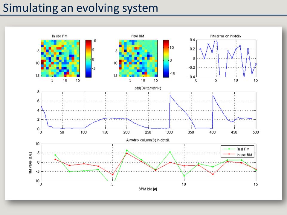
Simulating an evolving system

24
10 25 2 Excitation History Size Simulating an evolving system

25
Preliminary results

26
Very preliminary Linac Horizontal Orbit Correction (measurements done on 17/04/2013)
")
27
Preliminary results “Orbit matching” in TL1

28
Comparison with MADX model Calculating expected response matrix from MADX model.

29
Corrector Idx Comparison with MADX model At first look similar behavior as the predicted. The sign of many elements of the two matrices is opposite! BPM idx Corrector Idx BPM idx

30
Energy check A first issue: straight and delayed beam have different energy From a rough measurement, this offset is related to a Dp/p = -0.032 of the delayed beam. From a rough measurement, this offset is related to a Dp/p = -0.032 of the delayed beam.

31
Comparison with MADX model Better resolution of the errors. Overall wrong sign. Corrector 4 (CD.DHE0290) seems to be connected with wrong polarity. If energy of the beam is not matched with model, a change in dispersion because of a correction leads to a change in beam position. Effect can be taken into account by the model. BPM idx Corrector Idx
 seems to be connected with wrong polarity. If energy of the beam is not matched with model, a change in dispersion because of a correction leads to a change in beam position. Effect can be taken into account by the model. BPM idx Corrector Idx.")
32
Comparison with MADX model In depth view of the two response matrices

33
Comparison with MADX model In depth view of the two response matrices

34
Comparison with MADX model

35
In depth view of the two response matrices Comparison with MADX model

36
In depth view of the two response matrices Comparison with MADX model

37
In depth view of the two response matrices Comparison with MADX model

38
In depth view of the two response matrices Comparison with MADX model

39
In depth view of the two response matrices Comparison with MADX model

40
“Moving” a BPR signal changing klystron phases Work in progress: a different application

41
After first iteration Work in progress: a different application

42
After second iteration Work in progress: a different application

43
Other example with BPR475: before Work in progress: a different application

44
Other example with BPR475: before Work in progress: a different application

45
Summary

46
What has been done: -Developed and tested a generic linear feedback. -Smart way to measure the response matrix: it can work in quasi-parasitic mode and/or during orbit correction. -First results and characterization of possible limitations. -Comparison of the response matrix with machine model (MADX). -Found a corrector with inverted polarity. -Test of the feedback on a different application. What is ongoing: -Solve energy difference issue acting on injectors. -Improvement of the response matrix measurement algorithm. What is next: -Demonstrate the possibility to match the two orbits in TL1 within noise level. -Measure the improvement in beam emittance and power production stability.
. -Found a corrector with inverted polarity. -Test of the feedback on a different application. What is ongoing: -Solve energy difference issue acting on injectors. -Improvement of the response matrix measurement algorithm. What is next: -Demonstrate the possibility to match the two orbits in TL1 within noise level. -Measure the improvement in beam emittance and power production stability..")
47
Thank you.

48
Questions?

Similar presentations


, Jochem Snuverink (RHUL), Nuria Fuster (IFIC) 18 th ATF2 Project Meeting – Feb 24-26 2015 – LAPP, Annecy.>")

1 LINEAR LATTICE ERRORS AT THE ESRF: MODELING AND CORRECTION A. Franchi, L. Farvacque, T. Perron.>")

 for the FONT project group FONT meeting January 11, 2007.>")


 ATF2 Project Meeting 2015. 2 K. Kubo.>")

 28-Jan-2015 1.>")
 E. Adli (Univ. of Oslo), J. Resta Lopez (IFIC) In.>")
 A. Latina, J. Pfingstner, D. Schulte (CERN) E. Adli (Univ. of Oslo/SLAC) In collaboration with: F.J.>")

 for the FONT project group 5th ATF2 project meeting, KEK December 19-21, 2007.>")