Download presentation
Presentation is loading. Please wait.

1
Search for double electron capture in 106 Cd using HPGe detectors and Si pixel detectors Ivan Štekl for TGV collaboration Institute of Experimental and Applied Physics Czech Technical University in Prague TGV experiment – TGV II detector description, results of Phases I and II Present status - utilization of Si pixel detectors (MC simulations, results of background measurements) Future plans JINR Dubna, Russia IEAP CTU in Prague, Czech Republic CSNSM Orsay, France Since 2000, focus on 2 EC/EC decay of 106 Cd
 Future plans JINR Dubna, Russia IEAP CTU in Prague, Czech Republic CSNSM Orsay, France Since 2000, focus on 2 EC/EC decay of 106 Cd")
2
106 Cd 106 Ag 106 Pd 0+0+ 0+0+ 0+0+ 2+2+ 1133.8 511.9 511.9 622 Q(EC/EC) = 2770 keV 7.2 1.25% 1+1+ + + +/EC EC/EC 2νEC/EC 2KX Pd (~21 keV) (+ for e.s.) Main background: Cd KX-rays (~23 keV) +/EC KXPd + 2 511 (+ for e.s.) 2741.04+4+ 0νEC/EC KXPd + LXPd + 2741 ( 2229 + 512) 2229 2741 + + 4 511 (+ for e.s.) 1557.7 2717.6 3+3+ 1046 1160 0νEC/EC 2KXPd + ( 1160 + 1046 + 512)
 = 2770 keV % 1+1+ + + +/EC EC/EC 2νEC/EC 2KX Pd (~21 keV) (+ for e.s.) Main background: Cd KX-rays (~23 keV) +/EC KXPd + 2 511 (+ for e.s.) νEC/EC KXPd + LXPd + 2741 ( 512) 2229 2741 + + 4 511 (+ for e.s.) 1046 νEC/EC 2KXPd + ( 512)")
3
Laboratoire Souterrain de Modane, France Phase I ~ 10g (12 foils) of 106 Cd (75%) and ~ 3.2 g (4 foils) of Cd-nat., T= 8687h (Feb.2005 – Feb.2006) Phase II ~ 13.6 g (16 foils) of 106 Cd (75%), T ~ 12900h (Dec.2007 – July 2009) Background I no samples (Aug.2009 – March 2010) Background II 16 samples of Cd.-nat (April 2010 – …2011)
 of 106 Cd (75%) and ~ 3.2 g (4 foils) of Cd-nat., T= 8687h (Feb.2005 – Feb.2006) Phase II ~ 13.6 g (16 foils) of 106 Cd (75%), T ~ 12900h (Dec.2007 – July 2009) Background I no samples (Aug.2009 – March 2010) Background II 16 samples of Cd.-nat (April 2010 – …2011)")
4
Telescope Germanium Vertical (TGV-2) 32 HPGe planar detectors 60 mm x 6 mm with sensitive volume: 20.4 cm 2 x 6 mm Total sensitive volume: ~400 cm 3 Total mass of detectors: ~3 kg Total area of samples : 330 cm 2 Total mass of sample(s) : 10 25 g Total efficiency : 50 70 % E-resolution : 3 4 keV @ 60 Co LE-threshold : 40 50 keV (5 6 keV) Double beta emitters: 16 samples (~ 50 µm ) of 106 Cd (enrich.75%) 13.6 g ~ 5.79 x 10 22 atoms of 106 Cd HPGe Cd
 32 HPGe planar detectors 60 mm x 6 mm with sensitive volume: 20.4 cm 2 x 6 mm Total sensitive volume: ~400 cm 3 Total mass of detectors: ~3 kg Total area of samples : 330 cm 2 Total mass of sample(s) : 10 25 g Total efficiency : 50 70 % E-resolution : 3 4 60 Co LE-threshold : 40 50 keV (5 6 keV) Double beta emitters: 16 samples (~ 50 µm ) of 106 Cd (enrich.75%) 13.6 g ~ 5.79 x atoms of 106 Cd HPGe Cd")
5
TGV-2 Detectors: 32 HPGe Ø 60 mm x 6 mm Sensitive volume 20.4 cm 2 x 6 mm Total sensitive volume ~ 400 cm 3 Total mass ~3 kg Details of cryostat ~2500 g (Al, Cu, …) Al ~ 1200 g (including holders ~ 360 g) Cu ~ 1300 g
 Al ~ 1200 g (including holders ~ 360 g) Cu ~ 1300 g")
6
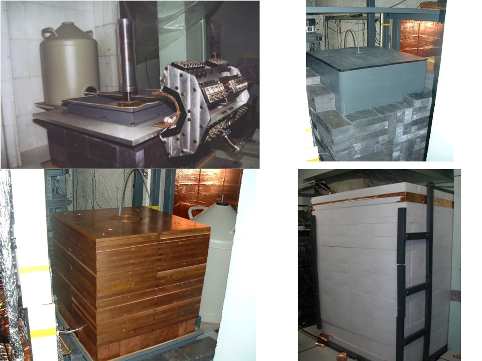
PASSIVE SHIELDING (located in LSM) Copper > 20 cm Airtight box Lead > 10 cm Polyethylene filled with boron 16 cm
 Copper > 20 cm Airtight box Lead > 10 cm Polyethylene filled with boron 16 cm")
8
Phase I final result acquisition with 10g of 106 Cd after 8687 hours: additional analysis (2D, different energy windows)
")
9
KXPd KXCd ROI Phase II, 13.6g of 106 Cd, T=12900h

10
Phase I Phase II EC/EC T 1/2 ≥ …(90%CL) T 1/2 ≥ … (90%CL) (0 + →0 +,g.s.) 3.0 x 10 20 yr 4.2 x 10 20 yr (0 + →2 + 1,512) 4.2 x 10 19 yr 1.2 x 10 20 yr (0 + →0 + 1,1334) 3.1 x 10 19 yr 1.0 x 10 20 yr 0 res.(0 + →4 +,2741) - 1.7 x 10 20 yr 0 res.(0 + → ?,2716) - 1.6 x 10 20 yr β + /EC (0 + →0 +,g.s.) 5.9 x 10 19 yr 1.1 x 10 20 yr (0 + →2 + 1,512) 5.9 x 10 19 yr 1.1 x 10 20 yr (0 + →0 + 1,1334) - 1.6 x 10 20 yr β + (0 + →0 +,g.s.) 6.0 x 10 19 yr 1.4 x 10 20 yr (0 + →2 + 1,512) 5.7 x 10 19 yr 1.7 x 10 20 yr 2 β + β + (0 + →0 +,g.s.) - 1.3 x 10 20 yr (N.I.Rukhadze et al., Nucl.Phys. A 852, 2011, 197-206)
.")
11
How it compares with calculations > 4.2 10 20 p.w. approaching closed

12
24 g of 106 Cd with enrichment of 98.4 % Plans on near future Planned measurements with 106 Cd: 1.TGV-2 (Ge detectors) ( ~14-15 g ) 2.600 cm 3 HPGe detector ( ~24 g ) (modes with ) 3.SPT (Pixel detectors) ( ~8-10 g )
 ( ~14-15 g ) cm 3 HPGe detector ( ~24 g ) (modes with ) 3.SPT (Pixel detectors) ( ~8-10 g )")
13
Approaches to double beta studies Segmented CdTe pixel detectors (enriched Cd) Signature = two tracks of electrons from one pixel, Bragg curve Particle identification / rejection (alpha, electrons, photons) Si pixel detectors in coincidence mode Thin foil of enriched isotope Signature = two hitted pixels with X- rays of precise energy Efficiency (factor 2x comparing with TGV II) Particle identification (alpha, electrons) Pixel R&D projects Setup based on semiconductor detectors TGV II COBRACUORESuperNEMOGERDA Detector = source Tracking + scintillator Low-temp. detector Semiconductor + segmentation COBRA extensionTGV III (EC/EC) Observable: 2× 21keV X-rays from 106 Pd daughter originated in the enriched Cd foil K1K1 K2K2 K1K1 K2K2 K1K1 K1K1 K2K2 Double-side eventSingle-side events
 Observable: 2× 21keV X-rays from 106 Pd daughter originated in the enriched Cd foil K1K1 K2K2 K1K1 K2K2 K1K1 K1K1 K2K2 Double-side eventSingle-side events.")
14
Timepix detector Portable tracking detector Room temperature & noiseless operation Chipboard + USB readout interface Vacuum operation, no cooling USB readout interface (developed in IEAP CTU in Prague), frame-rate up to 5 fps (USB 1.1) Compact size, Plug&Play, hot swap Fully USB powered Integrated source of variable detector bias voltage (5 – 100V) Pixelman software package + plugin for particle identification Pixelman software package (developed in IEAP CTU in Prague)
, frame-rate up to 5 fps (USB 1.1) Compact size, Plug&Play, hot swap Fully USB powered Integrated source of variable detector bias voltage (5 – 100V) Pixelman software package + plugin for particle identification Pixelman software package (developed in IEAP CTU in Prague)")
15
May 5, 2010 Pavel Cermak Response examples Particle type identification Clusters selected according to size, roundness, linearity,... AlphasElectronsMuons Muons + electrons 214 Bi 214 Po 210 Pb

16
a) MC results: KK events, source-detector distance = 1 mm D 34.5% of registered KK events D (0.7 – 4) mm => 68% of registered KK events Mean distance = 3.2 mm KK events, source-detector distance = 0 mm D 84.7% of registered KK events D 98.7% of registered KK events Mean distance = 1.2 mm b) For background measurement: D (0.7 – 4) mm => 25% of registered bg events Using distance cut D (0.7-4) mm Results of MC: Improving S/B ratio by factor of 2.6 Distance of pixels hit (comparison of MC and meas.) Bg measurement from LSM:
 MC results: KK events, source-detector distance = 1 mm D 34.5% of registered KK events D (0.7 – 4) mm => 68% of registered KK events Mean distance = 3.2 mm KK events, source-detector distance = 0 mm D 84.7% of registered KK events D 98.7% of registered KK events Mean distance = 1.2 mm b) For background measurement: D (0.7 – 4) mm => 25% of registered bg events Using distance cut D (0.7-4) mm Results of MC: Improving S/B ratio by factor of 2.6 Distance of pixels hit (comparison of MC and meas.) Bg measurement from LSM:")
17
1) Selection of materials, design of detector : to suppress intrinsic background 2) Background measurement with single Si pixel det.: surface + underground (LSM), 1 month; 1s + 0.1 s time window, Pb shield 3) Development of coincidence mode: stack of pixel detectors (face2face arrangement). Activities performed with Si pixel detectors

18
Intrinsic background Chipboard with Si detector Measured by low-background setup in Modane lab HPGe planar detector, 150cm 3, range 20keV – 1.5MeV Bonding (In+Sn)Readout chipEmpty PCBSi module 228 Th< 10 -8 < 0.2263 ± 8187 ± 11 234 Th< 10 -6 < 0.9168 ± 11123 ± 10 40 K< 10 -7 < 6.2< 25117 ± 28 Contributions per unit (comparison of samples and Si module) [mBq/unit]:
![Intrinsic background Chipboard with Si detector Measured by low-background setup in Modane lab HPGe planar detector, 150cm 3, range 20keV – 1.5MeV Bonding (In+Sn)Readout chipEmpty PCBSi module 228 Th< < ± 8187 ± Th< < ± ± K< < 6.2< ± 28 Contributions per unit (comparison of samples and Si module) [mBq/unit]:](http://images.slideplayer.com/31/9780285/slides/slide_18.jpg "Intrinsic background Chipboard with Si detector Measured by low-background setup in Modane lab HPGe planar detector, 150cm 3, range 20keV – 1.5MeV Bonding (In+Sn)Readout chipEmpty PCBSi module 228 Th< < ± 8187 ± Th< < ± ± K< < 6.2< ± 28 Contributions per unit (comparison of samples and Si module) [mBq/unit]:")
19
Intrinsic background (PCB material screening results) material Mass (g) Time (s) Unit 226 Ra 210 Pb 228 Ra 228 Th 40 K FR4 (original PCB) 12.3483466 mBq/Kg 14259± 486 10692± 160 17658± 972 21303± 648 <2025 (Kapton + Ad+Cu) 1.87505674 mBq/Kg 207±76<3200<215170±76<1760 Cu foil1.4764153 mBq/Kg <126<4500<293<146 595± 315 Adhesive0.8325685 mBq/kg <556<16000<1400 <9000 Coverlay (mask) 0.696294 mBq/Kg <1500<40000<3500 <28000 Cuflon14.1684738 mBq/Kg <16<134<39<16<280
 material Mass (g) Time (s) Unit 226 Ra 210 Pb 228 Ra 228 Th 40 K FR4 (original PCB) mBq/Kg 14259± ± ± ± 648 <2025 (Kapton + Ad+Cu) mBq/Kg 207±76<3200<215170±76<1760 Cu foil mBq/Kg <126<4500<293< ± 315 Adhesive mBq/kg <556<16000<1400 <9000 Coverlay (mask) mBq/Kg <1500<40000<3500 <28000 Cuflon mBq/Kg <16<134<39<16<280")
20
Background measurements with Si pixel detectors in LSM and IEAP CTU (1s or 0.1s time window) were finished. Measurement of background Location/ Description Prague IEAP 1 s frames LSM 1s frames Length 113 hours487 hours

21
Energy Spectrum (SSE = two X-rays registered in one frame by different pixels) 1 s frame PragueModane
 1 s frame PragueModane")
22
Energy Spectrum (SSE, distance between pixels 0.7mm - 4mm) 1s frame PragueModane
 1s frame PragueModane")
23
E1 vs E2 (SSE, 0.7mm - 4mm) PragueModane
 PragueModane")
24
All Double frames All doubleSSE 0.7 – 4 mm All events1076931883445931284 527008680678176 ROI (19,22) keV (from energy spectrum) 9001213913 6661123410 ROI (19,22) keV (from E1 vs E2) 000 000 Prague Modane Data given for 487 hours
 keV (from energy spectrum) ROI (19,22) keV (from E1 vs E2) Prague Modane Data given for 487 hours")
25
Timepix stack and other developments Timepix Stack Prototype tested with D class Timepix CuFlon Based PCB ready for wire bonding Considering Flexible PCB for next generation of stack Flexible PCB based design allows to keep the detector very close to each other First prototype ready and tested (face to face configuration) First prototype of CuFlon based chip board Current Timepix stack Planned next version Detectors face to face Flexible PCB Chip support (CuFlon or Pure copper) Detectors very near to each other Support system
 First prototype of CuFlon based chip board Current Timepix stack Planned next version Detectors face to face Flexible PCB Chip support (CuFlon or Pure copper) Detectors very near to each other Support system")
26
SPT setup proposal Estimation of limit for EC/EC decay of 106 Cd for 1 pair of Timepix quads: If background = 0 : T 1/2 > (e. t. N at. ln2) / ln (1-CL) = 1,95 × 10 20 years 90% CL ln (1-CL) = 2.3 e...... full efficiency (for SPT = 8,54 %) t...... time of measurement [years], expected 4 years N at... number of 106 Cd atoms in foil, 98% of enrichment N at = 1.89 × 10 21 atoms To reach limit of 10 21 years: We would need 5-7 quad Timepix pairs in 1. prototype (for 8 gr. we need 25-30 quad pairs)
 / ln (1-CL) = 1,95 × years 90% CL ln (1-CL) = 2.3 e full efficiency (for SPT = 8,54 %) t time of measurement [years], expected 4 years N at... number of 106 Cd atoms in foil, 98% of enrichment N at = 1.89 × atoms To reach limit of years: We would need 5-7 quad Timepix pairs in 1. prototype (for 8 gr. we need quad pairs).")
27
Summary and future plans Study of 2 EC/EC of 106 Cd, modes with gammas (HPGe detector) TGV-2 setup (based on HPGe detector telescope TGV) has provided result comparable with theoretical predictions 24 grams of 106 Cd (98.4% enrichment) available – TGV, SPT, background level Considering next generation setup SPT (Silicon Pixel Telescope) based on Si pixel detectors TimePix Heading for a prototype based on the four-fold Si Timepix stack (face-to-face arrangement) The study of the posibility to measure 0 EC/EC decay ( 152 Gd g.s., 112 Sn exc. state– resonance enhancement of the 0 EC/EC process if Q – Q r < 1 keV) Z.Sujkowski, S.Wycech, Phys. Rev. C70, 052501, 2004 J.Bernabeu, A. deRujula, C.Jarlskog, Nucl. Phys. B223, 15 (1983) signature – X-rays < 100 keV + or e - e + or Majoron advantage: good value of the rates between 0 EC/EC and 2 EC/EC processes
 Z.Sujkowski, S.Wycech, Phys. Rev. C70, , 2004 J.Bernabeu, A. deRujula, C.Jarlskog, Nucl. Phys. B223, 15 (1983) signature – X-rays < 100 keV + or e - e + or Majoron advantage: good value of the rates between 0 EC/EC and 2 EC/EC processes.")
28
Backup slides

29
2e b - + (A,Z) → (A,Z-2) + 2X + ( brem, 2 , e + e -, e- int ) E ,.. = M - e1 - e2 Suppression factor is ~ 10 4 (in comparison with EC +(0 )) – M. Doi and T. Kotani, Prog. Theor. Phys. 89 (1993)139. 0 EC/EC DECAY 0 EC/EC Resonance Conditions Q‘(E*) = M - E* - 2E b Q’res < 1 keV Enhancement factor can be on the level ~ 10 6 ! (for 112 Sn) - J. Bernabeu et.al., Nucl. Phys. B 223 (1983) 15 0 EC/EC Resonant Decay of 106 Cd M= 2770±7.2 keV E*= 2741.0 keV E K =24.3 keV E L =3.33 keV E*= 2717.6 keV E K =24.3 keV E K =24.3 keV
) – M. Doi and T. Kotani, Prog. Theor. Phys. 89 (1993) EC/EC DECAY 0 EC/EC Resonance Conditions Q‘(E*) = M - E* - 2E b Q’res < 1 keV Enhancement factor can be on the level ~ (for 112 Sn) - J. Bernabeu et.al., Nucl. Phys. B 223 (1983) 15 0 EC/EC Resonant Decay of 106 Cd M= 2770±7.2 keV E*= keV E K =24.3 keV E L =3.33 keV E*= keV E K =24.3 keV E K =24.3 keV.")
30
The calculated probability of detection of the peak of KX(Pd) Likelihood probability function of 21 keV events KXPd
 Likelihood probability function of 21 keV events KXPd")
31
KK TGV signal patterns β + β + -pair E1E1 E2E2 E1E1 E2E2 E1E1 E2E2 E1E1 E2E2 E 1 +E 2 = D D -paired E1=DE1=D E1E1 D -single E 1 =E 2 = K Pd D )-pair E1E1 E2E2 1. -pair + D -satellite (single or paired) E1E1 E2E2 2. E1E1 E2E2 E1E1 E2E2 E 1 +E 2 =511 keV 511 -paired E 1 =511 keV E1E1 511 -single E 1 <511 keV E1E1 511 -fired -pair candidate E1E1 E2E2 E1E1 E2E2 -pair + -satellite (single, paired, or fired) E2E2 E1E1 E 1 +E 2 != 511 keV
 E1E1 E2E2 2. E1E1 E2E2 E1E1 E2E2 E 1 +E 2 =511 keV 511 -paired E 1 =511 keV E1E1 511 -single E 1 <511 keV E1E1 511 -fired -pair candidate E1E1 E2E2 E1E1 E2E2 -pair + -satellite (single, paired, or fired) E2E2 E1E1 E 1 +E 2 != 511 keV.")
32
Comparision of background in Phase I and Phase II

33
Setup with 2 mm thick Si Timepix detector, source distance = 1 mm: Number of good KK-events registered in two pixels: 12.71 % - double-side events (DSE): 44.11 % - single-side events (SSE): 55.89 % - single-side events in adjacent pixels: 0.009 % Number of events with energy deposit in foil: 76.0 % Setup with 2 mm thick Si Timepix detector, source distance = 1 m: Number of good KK-events registered in two pixels: 16.66 % - double-side events (DSE): 42.32 % - single-side events (SSE): 57.68 % - single-side events in adjacent pixels: 0.16 % Number of events with energy deposit in foil: 76.2 % SPT efficiency of registration (compare with 5.5% for TGV-II): SPT MC simulations (2)
: % - single-side events (SSE): % - single-side events in adjacent pixels: % Number of events with energy deposit in foil: 76.0 % Setup with 2 mm thick Si Timepix detector, source distance = 1 m: Number of good KK-events registered in two pixels: % - double-side events (DSE): % - single-side events (SSE): % - single-side events in adjacent pixels: 0.16 % Number of events with energy deposit in foil: 76.2 % SPT efficiency of registration (compare with 5.5% for TGV-II): SPT MC simulations (2)")
34
Background signal measurement E1.vs.E2 SSE Entries 15 20 days of experimental data from LSM, shielded 5cm of Pb, 1s frames ROI Energy spectrum (up to 300keV) Looking for SSE candidates (2 clusters in the frame) Only random coincidences, 0 events in the ROI (19-23 keV)
 Looking for SSE candidates (2 clusters in the frame) Only random coincidences, 0 events in the ROI (19-23 keV)")
35
Next step – using stack of Timepix detectors To build a prototype based on the four-fold Timepix stack Developed slightly modified boards allowing face-to-face configuration Further optimization of the chip carrier board (material of PCB, minimizing amount of material close to the chip)
")
Similar presentations

 List of projects: 1) TGV experiment – measurement of 2 EC/EC decay of 106.>")

, crystals array and kapton.>")


, Ph. Hubert 2), A. Nachab 2) and V. Umatov 1) 1) ITEP, Moscow, Russia 2) CNBG, Gradignan,>")
, F. Hubert 2), Ph. Hubert 2), A. Nachab 2) and V. Umatov 1) 1) ITEP, Moscow,>")


 HEP-EPS 2003 conference CENBG, IN2P3-CNRS et Université de Bordeaux, France CFR,>")

 TAUP2007 - Sendai September 07.>")