Download presentation
Presentation is loading. Please wait.

1
RHIC polarized source upgrade. A.Zelenski, BNL

2
Workshop on high–energy spin physics, IHEP, Protvino, September 1983 Workshop on high–energy spin physics, IHEP, Protvino, September 1983 Yaroslav Derbenev “Siberian snakes” Anatoli Zelenski A new polarization technique. Equal intensity for polarized and unpolarized proton beams.

3
RHIC: the “Polarized” Collider STAR PHENIX AGS, 24GeV LINAC BOOSTER, 2.5 GeV Pol. H - ion source Spin Rotators 20% Snake Siberian Snakes 200 MeV polarimeter RHIC pC “CNI” polarimeters RHIC Absolute H-jet polarimeter Design goal - L max = 1.6 10 32 s -1 cm -2 50 < √s < 500 GeV AGS pC “CNI” polarimeter 5% Snake Polarization facilities at RHIC.

4
Operational Polarized H - Source at RHIC. RHIC OPPIS produces reliably 0.5-1.0mA polarized H - ion current. Polarization at 200 MeV: P = 80%. Beam intensity (ion/pulse) routine operation: Source - 10 12 H - /pulse Linac - 5∙10 11 AGS - 1.5-2.0 ∙ 10 11 RHIC - 1.5∙10 11 (protons/bunch). A 29.2 GHz ECR-type source is used for primary proton beam generation. The source was originally developed for dc operation. A ten-fold intensity increase was demonstrated in a pulsed operation by using a very high-brightness Fast Atomic Beam Source instead of the ECR proton source.
 routine operation: Source H - /pulse Linac - 5∙10 11 AGS ∙ RHIC - 1.5∙10 11 (protons/bunch). A 29.2 GHz ECR-type source is used for primary proton beam generation. The source was originally developed for dc operation. A ten-fold intensity increase was demonstrated in a pulsed operation by using a very high-brightness Fast Atomic Beam Source instead of the ECR proton source..")
5
SPIN -TRANSFER POLARIZATION IN PROTON-Rb COLLISIONS. Rb + H+H+ H+H+ Proton source Proton source Laser-795 nm Optical pumping Rb: NL(Rb) ~10 14 cm -2 Sona transition Sona transition Ionizer cell Ionizer cell H-H- Laser beam is a primary source of angular momentum: 10 W (795 nm) 410 19 h /sec 2 A, H 0 equivalent intensity. Supperconducting solenoid 25 кГс 1.5 kG field Charge-exchange collisions: ~10 -14 cm 2 Na-jet ionizer cell: NL(Na)~ 310 15 cm -2 Electron to proton polarization transfer ECR-29 GHz Н + source Rb +
 ~10 14 cm -2 Sona transition Sona transition Ionizer cell Ionizer cell H-H- Laser beam is a primary source of angular momentum: 10 W (795 nm) h /sec 2 A, H 0 equivalent intensity. Supperconducting solenoid 25 кГс 1.5 kG field Charge-exchange collisions: ~ cm 2 Na-jet ionizer cell: NL(Na)~ cm -2 Electron to proton polarization transfer ECR-29 GHz Н + source Rb +.")
6
Schematic layout of the RHIC OPPIS. 29.2 GHz ECR proton source 29.2 GHz ECR proton source SCS solenoid Probe laser Na-jet Ionizer cell Na-jet Ionizer cell Pumping laser Cryopumps Sona-transition Rb-cell SCS -solenoid

7
Pulsed OPPIS with the atomic hydrogen injector at INR, Moscow, 1982-1990. First generation. Atomic H injector Helium ionizer cell ~80% ionization efficiency. Lamb-shift polarimeter H - current 0.4mA, P=65%

8
Pulsed OPPIS at TRIUMF, 1997-99. Second generation. A pulsed H - ion current of a 10 mA was obtained in 1999. Atomic H Injector.

9
OPPIS with atomic H injector layout. RHIC 2012. The third generation.

10
OPPIS with atomic H injector layout. Atomic H injector Neutralizer cell He-ionizer cell Rb-cell Na-jet cell H+H+ H0H0 H+H+ H0H0 H-H- H2 HeRbNa TMP1 CP1

11
Hydrogen atomic beam ionization efficiency in the He- cell. 10 keV 80% H 0 + He → H + + He + e

12
H - yield vs beam energy ~ 8.4 % at 3.0 keV beam energy

13
A result of this “upgrade” is practically a new source. A new superconducting solenoid. A new atomic hydrogen injector. A new vacuum system. A new H-ionizer cell, energy separation system and pulsed PS system. A new control and interlock system. Major upgrades of laser system. Major modifications of the Low Energy Beam Transport system. Major upgrades in 200 MeV polarimeter. A new test-bench for atomic injector studies. Many other upgrades…

14
“Fast Atomic Beam Source”, BINP 2011 Plasmatron 4-grid proton extraction system H2 Neutralization cell ~ 3.5 A equivalent H 0 beam FABS produces 200-300 mA equivalent H0 beam intensity Within the Na-jet ionizer acceptance.

15
FABS and neutralizer cell.

16
FABS 4-grid spherical Ion Optical System (IOS).
.")
17
Superconducting Solenoid Sona transition Ionizer solenoid Large Correction Coil OPPIS magnetic field, Sona-transition field shape control. Internal Correction Coils

18
Atomic Beam Mode, flattop. 65 cm flattop 30 kG

19
He-ionizer cell and three-grid energy separation system. He-pulsed valve 3-grid beam deceleration system

20
Sodium-jet ionizer cell Reservoir– operational temperature. Tres. ~500 о С. Nozzle – Tn ~500 о С. Collector- Na-vapor condensation: Tcoll.~120 о С Trap- return line. T ~ 120 – 180 о С. Transversal vapor flow in the N-jet cell. Reduces sodium vapor losses for 3-4 orders of magnitude, which allow the cell aperture increase up to 3.0 cm. Transversal vapor flow in the N-jet cell. Reduces sodium vapor losses for 3-4 orders of magnitude, which allow the cell aperture increase up to 3.0 cm. Nozzle 500deg.C Collector ~150 deg.C Reservoir ~500 deg.C NL ~2·10 15 atoms/cm 2 L ~ 2-3 cm

21
H - beam acceleration to 35 keV at the exit of Na-jet ionizer cell Na-jet cell is isolated and biased to – 32 keV. The H - beam is accelerated in a two-stage acceleration system. -32 kV H - 35 keV -28 keV-15 keV

22
H - beam acceleration to 35 keV at the exit of Na-jet ionizer cell Na-jet cell is isolated and biased to – 32 keV. The H - beam is accelerated in a two-stage acceleration system. -32 kV H - 35 keV -28 keV-15 keV

23
New PLC interlock and monitoring system. Graphics by Yuri Bezpalko

24
H - ion beam current pulse -560 uA at 200 MeV, Rb-96 deg, May 3, 2013 H- ion beam current-700 uA at injection to RFQ

25
Polarized injector, 200 MeV linac and injection lines. OPPIS 200 MeV polarimeter Polarization direction is adjusted vertically in the 750 keV beamline by the solenoidal spin - rotator.

26
Source intensity and polarization. Rb-cell, Temp., deg. C81869196 Linac Current, μA295370430570 Booster Input ×10 11 4.96.27.39.0 Pol. %, at 200 MeV 84 83 80.5 78 Reliable long-term ∙operation of the source was demonstrated. Very high suppression of un-polarized beam component was demonstrated. Small beam emittance (after collimation for energy separation) and high transmission to 200 MeV.
 and high transmission to 200 MeV..")
27
H - beam current and polarization at 200 MeV vs. Rb vapor thickness Rb-vapor thickness –nL ( × 10 13 atoms/cm 2 ) H - current (uA) Polarization in 200 MeV polarimeter
 H - current (uA) Polarization in 200 MeV polarimeter.")
28
Magnetic field in Rb-cell, kG Polarization (at 200 MeV) vs. Superconducting Solenoid magnetic field in He and Rb-cells.

29
Depolarization caused by spin-orbital (LS) interaction in excited 2P states. ~92% at 20 kG –low limit Most of the H aoms are produced in excited n=2 states. A high magnetic field has to be Applied in the optically-pumped vapor cell to avoid depolarization due to spin-orbital interaction.

30
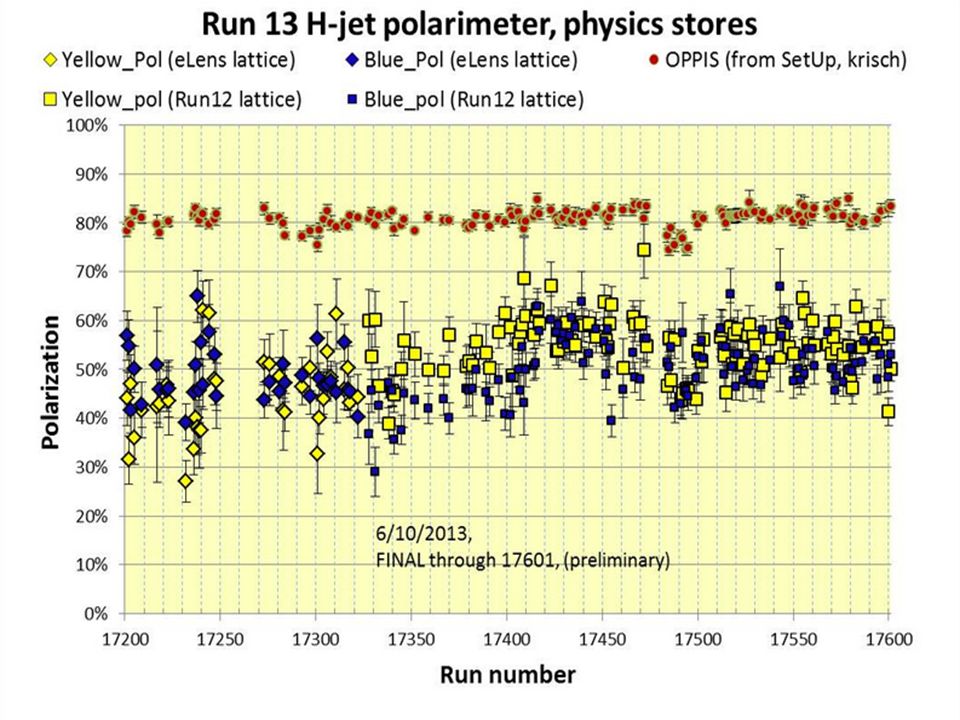
Polarization measurements at 255 GeV in H-jet polarimeter, Run-2013, April-25-30

31
Rb-81, T9-current-295 uA, (Booster input-4.9×10 11 ) 83.9+/0.9% 84.2+/-0.5%
 83.9+/0.9% 84.2+/-0.5%")
32
9/12/2013G.Atoian Total: 0.85 - 0.90 P = E H2 ∙ P Rb ∙ S ∙ B RG ∙ E LS ∙ E ES ∙ E Sona ∙ E ion ~ 85-90% Depolarization factors Depol. factorProcessEstimate 1E H2 Dilution due H 2 + in the new source (LEBT)0.99 - 0.99 2P Rb Rb-optical pumping (Laser system)0.99 - 0.99 3SRb polarization spatial distribution (Collimators)0.97 - 0.98 4B RG Proton neutralization in residual gas (Vacuum)0.98 - 0.99 5E LS Depolarization due to spin-orbital interaction0.98 - 0.99 6E ES Dilution due to incomplete energy separation not polarized component of the beam (LEBT) 0.98 - 0.99 7E Sona Sona-transition efficiency (Adjustment)0.96 - 0.98 8E ion Incomplete hyperfine interaction breaking in the ionizer magnetic field 0.98 - 0.99 9/12/2013G.Atoian 32
 P Rb Rb-optical pumping (Laser system) SRb polarization spatial distribution (Collimators) B RG Proton neutralization in residual gas (Vacuum) E LS Depolarization due to spin-orbital interaction E ES Dilution due to incomplete energy separation not polarized component of the beam (LEBT) E Sona Sona-transition efficiency (Adjustment) E ion Incomplete hyperfine interaction breaking in the ionizer magnetic field /12/2013G.Atoian 32.")
34
OPPIS LINAC Booster AGS RHIC (2.0-2.2) ∙10 11 p/bunch 0.6mA x 300us→11∙10 11 polarized H - /pulse. (6.0-6.5) ∙10 11 polarized H - /pulse at 200 MeV (2.2-2.4) ∙10 11 protons /pulse at 2.3 GeV ~1.8∙10 11 p/bunch, P~60-65% at 100 GeV P ~ 56% at 250 GeV RHIC Polarized beam in Run 2012
 ∙10 11 polarized H - /pulse at 200 MeV ( ) ∙10 11 protons /pulse at 2.3 GeV ~1.8∙10 11 p/bunch, P~60-65% at 100 GeV P ~ 56% at 250 GeV RHIC Polarized beam in Run")
35
Summary The new source is working. Reliable long-term operation at steady current and polarization. The maintenance time is significantly reduced. Polarization is 80-84%, which is 3-5% higher then ECR-based source. It is expected that polarization can be further improved to over 85%. The source intensity is about 3-5 mA. Due to strong space- charge effects only fraction of this current is transported and accelerated in RFQ and Linac. These losses can be reduced.

36
Optical pumping of Rb-85 (72.7%), Rb-87(27.8%) natural mixture.. Effective width of Rb 85-87 natural mixture including hyperfine Splitting and Doppler broadening is ~ 3.2 GHz Δν ~ 8 GHz

37
Beam intensity and polarization vs. He-valve setpoint

38
Reference polarization measurements in AGS for RHIC fills. Beam intensity ~ 2*10^11 RHIC fill # 200 MeV polarization illNumber = 17417, sourcePol_run_fy13 = 82.5573 fillNumber = 17417, agsPolT1_run_fy13 = 71.3816 Fixed target measurements: P f. = P f / √(1 +R) ~ P f (1- ½ R h ) Pf-fixed target measurement 70%
 ~ P f (1- ½ R h ) Pf-fixed target measurement 70%.")
Similar presentations