Download presentation
Presentation is loading. Please wait.

1
JUMP, LOOP, AND CALL INSTRUCTIONS
CHAPTER 3 JUMP, LOOP, AND CALL INSTRUCTIONS

2
Looping Repeating a sequence of instructions a certain number of times is called a loop Loop action is performed by DJNZ reg, Label The register is decremented If it is not zero, it jumps to the target address referred to by the label Prior to the start of loop the register is loaded with the counter for the number of repetitions Counter can be R0 – R7 or RAM location A loop can be repeated a maximum of 256 times

3
Looping (cont.)
")
4
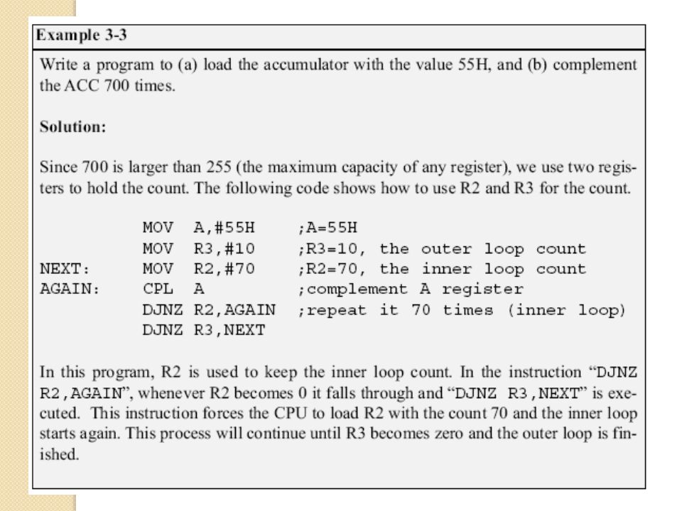
Nested Loop If we want to repeat an action more times than 256, we use a loop inside a loop, which is called nested loop We use multiple registers to hold the count

6
Conditional Jumps Jump only if a certain condition is met
JZ (jump if A = 0) The content of register A is checked. If it is zero, it jumps to the target address. OVER:
 The content of register A is checked. If it is zero, it jumps to the target address. OVER:")
8
Conditional Jumps (cont.)
JNZ (jump if A ≠ 0) The content of register A is checked. If it is not zero, it jumps to the target address.
 The content of register A is checked. If it is not zero, it jumps to the target address.")
9
Conditional Jumps (cont.)
JNC label ;jump if no carry, CY=0 If CY = 0, the CPU starts to fetch and execute instruction from the address of the label If CY = 1, it will not jump but will execute the next instruction below JNC All conditional jumps are short jumps The address of the target must within -128 to bytes of the contents of PC

11
Unconditional Jumps The unconditional jump is a jump in which control is transferred unconditionally to the target location LJMP (long jump) 3-byte instruction First byte is the opcode Second and third bytes represent the 16-bit target address Any memory location from 0000 to FFFFH
 3-byte instruction. First byte is the opcode. Second and third bytes represent the 16-bit target address. Any memory location from 0000 to FFFFH.")
12
Unconditional Jumps (cont.)
SJMP (short jump) 2-byte instruction First byte is the opcode Second byte is the relative target address 00 to FFH Forward +127 and backward -128 bytes from the current PC To calculate the target address of a short jump (SJMP, JNC, JZ, DJNZ, etc.) The second byte is added to the PC of the instruction immediately below the jump If the target address is out of range, the assembler will generate an error
 2-byte instruction. First byte is the opcode. Second byte is the relative target address 00 to FFH. Forward +127 and backward -128 bytes from the current PC. To calculate the target address of a short jump (SJMP, JNC, JZ, DJNZ, etc.) The second byte is added to the PC of the instruction immediately below the jump. If the target address is out of range, the assembler will generate an error.")
13
Calculating Short Jump Address

14
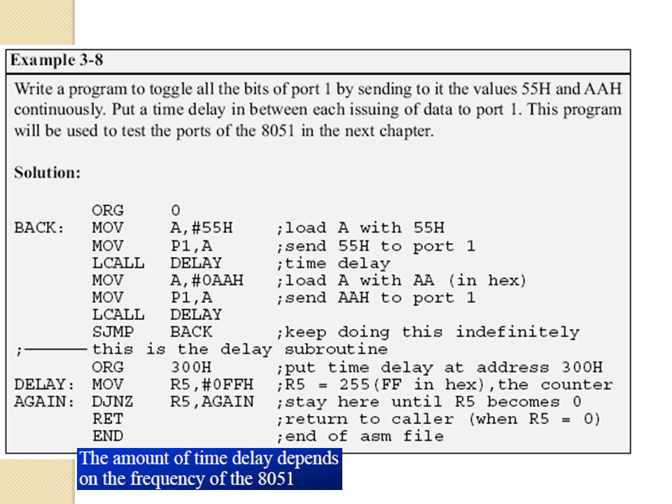
CALL INSTRUCTIONS Call instruction is used to call subroutine
Subroutines are often used to perform tasks that need to be performed frequently This makes a program more structured in addition to saving memory space LCALL (long call) 3-byte instruction First byte is the opcode Second and third bytes are used for address of target subroutine Subroutine is located anywhere within 64K byte address space
 3-byte instruction. First byte is the opcode. Second and third bytes are used for address of target subroutine. Subroutine is located anywhere within 64K byte address space.")
15
CALL INSTRUCTIONS (cont.)
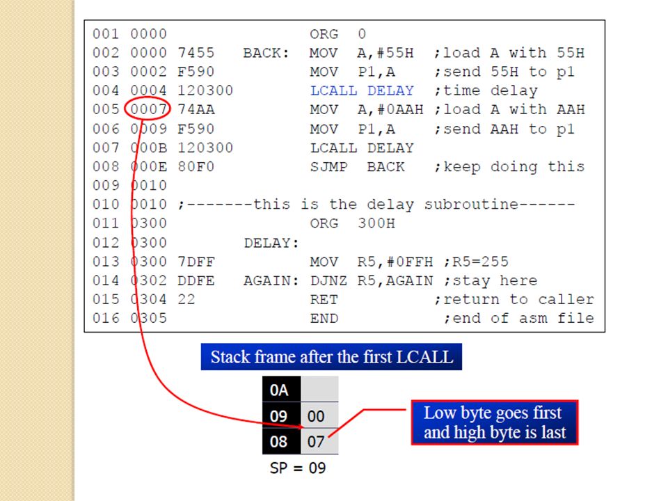
ACALL (absolute call) 2-byte instruction 11 bits are used for address within 2K-byte range When a subroutine is called, control is transferred to that subroutine The processor saves on the stack the the address of the instruction immediately below the CALL It also begins to fetch instructions from the new location
 2-byte instruction. 11 bits are used for address within 2K-byte range. When a subroutine is called, control is transferred to that subroutine. The processor saves on the stack the the address of the instruction immediately below the CALL. It also begins to fetch instructions from the new location.")
16
CALL INSTRUCTIONS (cont.)
After finishing execution of the subroutine The instruction RET transfers control back to the caller Every subroutine needs RET as the last instruction RET pops the address from the stack into the PC and resumes executing the instructions after the CALL

20
Calling Subroutines

21
ACALL The only difference between ACALL and LCALL is
The target address for LCALL can be anywhere within the 64K byte address The target address of ACALL must be within a 2K-byte range The use of ACALL instead of LCALL can save a number of bytes of program ROM space

22
ACALL (cont.)
")
23
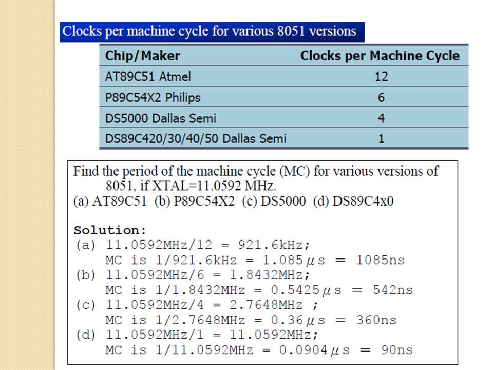
TIME DELAY FOR VARIOUS 8051 CHIPS
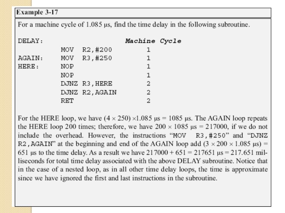
CPU executing an instruction takes a certain number of clock cycles These are referred as to as machine cycles The length of machine cycle depends on the frequency of the crystal oscillator connected to 8051 In original 8051, one machine cycle lasts 12 oscillator periods

24
TIME DELAY FOR VARIOUS 8051 CHIPS (cont.)
")
29
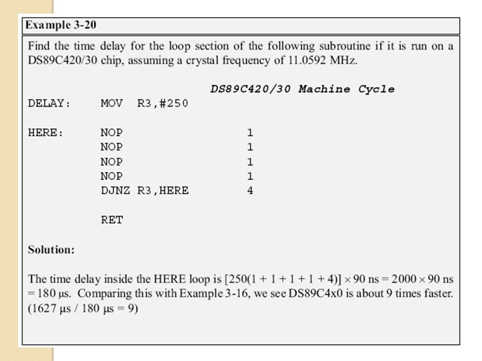
Delay Calculation for Other 8051
Two factors can affect the accuracy of the delay: Crystal frequency The duration of the clock period of the machine cycle is a function of this crystal frequency 8051 design The original machine cycle duration was set at 12 clocks Advances in both IC technology and CPU design in recent years have made the 1-clock machine cycle a common feature

Similar presentations


 that is reserved for storage of temporary data The data may represent.>")


