Download presentation
Presentation is loading. Please wait.

1
Dr. Awais Majeed awais.majeed@bcs.org Object Oriented Design and UML

2
Object-Oriented Paradigm Describing the software solution in terms of collaborating objects, with responsibilities. Objects, classes, encapsulation, States, inheritance, composition, polymorphism

3
Benefits of OO Enjoys all the benefits of Modular approach Dependencies can be handled by finding the commonalities through inheritance and polymorphism. Built-in libraries in OOP. Naturalness OO paradigm models the real world better because everything in real world is an object. Reusability Using the existing classes or components in future design, without much effort.

4
Structured vs Object Oriented Paradigm In structured design, data and functions are kept separately. Usually all of the data are placed before any of the functions are written. Sometimes, it is not intuitively known which data works with which function. In OO design, the related data and functions of an object are placed together within one unit.

5
Software Design in terms of Objects Objects are abstractions of real-world or system entities and manage themselves. Objects are independent and encapsulate state and representation information. System functionality is expressed in terms of object services. Objects communicate by message passing.

6
Objects & Object Classes An object is an entity that has a state and a defined set of operations which operate on that state. Objects are created according to some object class definition. An object class definition serves as a template for objects. It includes declarations of all the attributes and services which should be associated with an object of that class.

7
Object Communication Conceptually, objects communicate by message passing. Messages The name of the service requested by the calling object; Copies of the information required to execute the service and the name of a holder for the result of the service. In practice, messages are often implemented by procedure calls Name = procedure name; Information = parameter list.

8
Objected Oriented Design Using UML

9
Object Oriented Design using UML UML (Unified Modelling Language) is a standard notation to represent software design. Based on OO approaches. Has syntax rules Can be extended using stereotypes

10
Advantages of UML Specify, visualize, and document models of software systems Current and new systems Structure and design Behavior and interaction De facto standard (Tool Support!) Unambiguous and consistent notation Documentation
 Unambiguous and consistent notation Documentation")
11
UML Metamodel

12
Where can UML be used? 1. Business Model using Activity Diagram 2. Requirements Capture using Use Case Diagram 3. Requirements Analysis using Use Case Details and Class Diagram 4. Initial Design using Sequence Diagrams and second version of Class Diagram 5. Requirements Analysis using State Diagram 6. Architecture Design using Packages and Subsystems 7. Design using next level of details for Class Diagram

13
Where can UML be used?... 9. System Architecture using Deployment Diagram 10. Design using Design Patterns 11. Detailed design using Collaboration Diagram 12. Consolidate all information into Class Diagram 13. Detailed design using Component Diagram Refine all models through iterations Implement the models by translating into code Deploy software within operational environment

14
UML Modelling Use Case View Logical View Dynamic View Implementation View Deployment View

15
Use-case View Gathering requirements Functional & non-functional requirements Document functional requirements UML Use Case Diagram Use Case Description Documents Identify actor(s) and association to use case Create different levels of use cases (re-use!)
 and association to use case Create different levels of use cases (re-use!)")
16
Logical View Identify entities/things used in use case Identify attributes Identify operations Identify entity relations Identify multiplicity Create class diagram

17
Dynamic View Identify objects involved Identify interactions (messages) Use public operations Describe how things work
 Use public operations Describe how things work")
18
Implementation View This view concentrates on taking the Logical view and dividing the logical entities into actual software components. Components Component Diagrams Hierarchy of Classes and Packages

19
Deployment View The deployment view shows the hardware topology (e.g. computers and devices) on which the physical system executes. Hardware elements are called nodes. The view is composed of deployment diagrams.
 on which the physical system executes. Hardware elements are called nodes. The view is composed of deployment diagrams..")
20
Use-cases To describe functional System Specifications To provide starting point for System Design (including GUI) To provide basis for System Verification tests To provide a quick checkout for the customer
 To provide basis for System Verification tests To provide a quick checkout for the customer")
21
The Scope of Use Cases Analyst Architect Tester User Programmer Analysis Capture use cases Design and Implementation Implement use cases Verify that use cases are satisfied Test Use cases make up the glue Understands Verifies Designs Implements Use Case Expresses

22
Use Cases Use case diagram. Detailed use case document

23
Use Case Diagram UML artifact to represent the overall system specifications. A way to conceive and illustrate the use cases. Shows system boundary, main functionalities, the external entities which can interact with the system.

24
Notations Used System boundary Actors Use-cases Flow of information / stimulus

25
Actors An actor is an external agent that interacts with the system An actor stimulates the system with input events, or receives something from it.

26
Use Case Describes a process from the user’s point of view expressed in the user’s language A collection of interactions between the system and actors A Use Case is an end-to-end process description that includes many steps or transactions. Maintain Orders

27
Example: POS

28
Use Case Document A narrative document that describes the sequence of system events and the system responses originating from the initiating actors of the system. A use case tells a story of actors using a system A use-case is a sequence of actions a system performs that yields an observable result of value to a particular actor.

29
Terms and Concepts Actor: something with behavior, such as a person, computer system, or organization, e.g. a cashier. Scenario: specific sequence of actions and interactions between actors and the system under discussion, e.g. the scenario of successfully purchasing items with cash. Use case: a collection of related success and failure scenarios that describe actors using a system to support a goal.

30
Scenarios Main Success Scenario The normal flow of processing e.g., A customer arrives at a checkout with items to return. The cashier uses the POS system to record each returned item Alternate Scenario If normal flow deviates, then the alternate course of action e.g., If the credit authorization is reject, inform customer and ask for an alternative payment method. If item identifier not found in the system, notify the Cashier and suggest manual entry of the identifier code.

31
Things to remember! Choose the system boundary. Identify primary actors. Those that have user goals fulfilled through using services of the system For each actor, identify their user goals. Tabulate findings in the Vision artifact. Define use cases that satisfy user goals; name them according to their goal.

32
Example: Fully dressed Use Case Use case UC1: Process Sale Primary Actor: Cashier Stakeholders and Interests: -Cashier: Wants accurate and fast entry, no payment errors, … -Salesperson: Wants sales commissions updated. Preconditions: Cashier is identified and authenticated. Success Guarantee (Postconditions): -Sale is saved. Tax correctly calculated. Main success scenario (or basic flow): [on next slide] Extensions (or alternative flows): [on next slide] Special requirements: Touch screen UI, … Technology and Data Variations List: -Identifier entered by bar code scanner,… Open issues: What are the tax law variations? …
: -Sale is saved. Tax correctly calculated. Main success scenario (or basic flow): [on next slide] Extensions (or alternative flows): [on next slide] Special requirements: Touch screen UI, … Technology and Data Variations List: -Identifier entered by bar code scanner,… Open issues: What are the tax law variations. ….")
33
UC1: Process Sale Main success scenario (or basic flow): The Customer arrives at a POS checkout with items to purchase. The cashier records the identifier for each item. If there is more than one of the same item, the Cashier can enter the quantity as well. The system determines the item price and adds the item information to the running sales transaction. The description and the price of the current item are presented. On completion of item entry, the Cashier indicates to the POS system that item entry is complete. The System calculates and presents the sale total. The Cashier tells the customer the total. The Customer gives a cash payment (“cash tendered”) possibly greater than the sale total. Extensions (or alternative flows): If invalid identifier entered. Indicate error. If customer didn’t have enough cash, cancel sales transaction.
 possibly greater than the sale total. Extensions (or alternative flows): If invalid identifier entered. Indicate error. If customer didn’t have enough cash, cancel sales transaction..")
34
Logical View Identify entities/things used in use case Identify attributes Identify operations Identify entity relations Identify multiplicity Aim is to create class diagram

35
Identify Entities After defining the use cases, the next step is to cross the system boundary. Open the system “black box”. Think of the whole system in terms of entities, concepts or objects.

36
Concept Category List

37
How to represent entities? A Domain Model is used to represent entities and it illustrates meaningful concepts in a problem domain. It is a representation of real-world things, not software components. It is a set of static structure diagrams; no operations are defined. It may show: concepts associations between concepts attributes of concepts

38
Example: POS

39
Identify Attributes An attribute is a logical data value of an object. For example, a Sales receipt normally includes a date and time. The Sale concept would need a date and time attribute.

40
Attributes … Keep attributes simple. The type of an attribute should not normally be a complex domain concept, such as Sale or Airport. Attributes in a Domain Model should preferably be Pure data values: Boolean, Date, Number, String, … Simple attributes: color, phone number, zip code, universal product code (UPC),...
,....")
41
Identify Operations Add operations/method names by analyzing the interaction diagrams. The methods for each class can be identified by analyzing the interaction diagrams.

42
Identify Entity Relations The relationships between the entities identified earlier are known as associations. An association is a relationship between concepts that indicates some meaningful and interesting connection. Associations can be named. Associations can be identified using common association list.

43
Identify Multiplicities Multiplicity defines how many instances of a type A can be associated with one instance of a type B, at a particular moment in time. For example, a single instance of a Store can be associated with “many” (zero or more) Item instances.
 Item instances..")
44
Putting it all together: POS Class Diagram

45
Dynamic View Identify objects involved Identify interactions (messages) Use public operations Describe how things work UML dynamic views are used to express and model the behavior of a system over time, presented through state machine, interaction, and activity diagrams.
 Use public operations Describe how things work UML dynamic views are used to express and model the behavior of a system over time, presented through state machine, interaction, and activity diagrams.")
46
State Machines State machine diagrams capture the behavior of a software system. State machines can be used to model the behavior of a class, subsystem, or entire application. They also provide an excellent way to model communications with external entities via a protocol or event-based system.

47
Example-1 The door can have either open state or closed during its life-cycle. The door changes a state upon triggering of an event.

48
Example-2 The transition can have a guard condition for triggering an event as well as an action fired by the transition.

49
Sub-states A state allows nesting to contain Substates. A substate inherits the transitions of its superstate (the enclosing state). Within the Active state, and no matter what substate the object is in, if the on hook event occurs, a transition to the idle state occurs
. Within the Active state, and no matter what substate the object is in, if the on hook event occurs, a transition to the idle state occurs.")
50
Example

51
Interaction Diagrams Interaction diagrams illustrate how objects interact via messages. They can be: Collaboration/Communication Diagram Sequence Diagram Communication diagrams illustrate object interactions in a graph or network format. Sequence diagrams illustrate interactions in a kind of fence format.

53
Communication Diagrams Previously known as Collaboration Diagrams. They provide a bird’s eye-view of a collection of collaborating objects. Show the message flow between objects in an OO application and also imply the basic associations (relationships) between classes.
 between classes..")
54
Example - makePayment

55
Sequence Diagrams Sequence diagrams are used to display the interaction among users, screens, objects, and entities within the system. They provide a sequential map of message passing between objects over time.

56
Example - makePayment

57
Elements of Interaction Diagrams A message can be sent from an object to itself. A message can be conditional and is shown by following a sequence number with a conditional clause in square brackets. Iteration is indicated by following the sequence number with a star *.

58
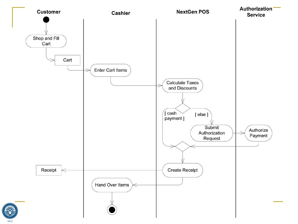
Activity Diagram Important for modeling system functions. Emphasizes the flow of objects and synchronization of the flow in support of parallel processing. An extension of the old "flow chart" diagram combined with Petri nets.

59
Example-1

61
Example-2

63
Modelling Signals Helpful in modeling events i.e., time triggering an action, or a cancellation request.

65
References and further Reading “Applying UML and Patterns: An Introduction to Object-Oriented analysis and design and iterative development ” 3 rd ed. By Craig Larman Ch 9: Domain Models Ch 10: System Sequence Diagrams Ch 15: UML Interaction Diagrams Ch 28: UML Activity Diagrams and Modeling

Similar presentations


 enclosed in a box.>")


 Software Engineering, 6 th edition: Chapter 12 )>")


>")


>")


