Download presentation
Presentation is loading. Please wait.

1
Another Modular Focal Plane: Part 1 – Sub-modules Bruce C. Bigelow University of Michigan Department of Physics 5/17/04

2
2 Focal Plane Sub-modules Motivations: install/remove single detectors from “front” of FP assemble detectors in modules of 3 x 3 simplify assembly, integration, and test reduce part counts, simplify part design simplify part fabrication individual module thermal control (Vis vs. IR) optimize materials for detector packages (CTE) local, discrete control of focal plane surface height minimize mechanical mass minimize thermal time constants minimize gravity deflections for ground testing maximize resonant frequencies
 optimize materials for detector packages (CTE) local, discrete control of focal plane surface height minimize mechanical mass minimize thermal time constants minimize gravity deflections for ground testing maximize resonant frequencies.")
3
3 Focal Plane Sub-modules Requirements: final focal plane flatness: +/- 25 microns support different optimal temperatures for Vis and IR detector temperature stability +/- 1K high stiffness – high first resonance

4
4 Focal Plane Sub-modules This talk: sub-module designs sub-module FEA

5
5 IR sub-module Rockwell H2RG package

6
6 IR sub-module Rockwell H2RG package with filter and frame

7
7 IR sub-module Rockwell H2RG package on moly MZT sub-plate

8
8 IR sub-module Rockwell H2RG 3 x 3 sub array

9
9 IR sub-module 3 x 3 sub array with flexure mounts

10
10 IR sub-module Sub-array with CRICs, flex circuits, connectors, local IR electronics (cold), sub-plate heater
, sub-plate heater")
11
11 IR sub-module Finished IR module with aperture mask

12
12 CCD sub-module Finished CCD module with aperture mask

13
13 Sub-module FEA FE Analyses: Static analysis – gravity deflections package mass modeled by doubling sub-plate density moly packages and sub-plate, invar flexures omit package cutouts, mounting holes, etc. focal plane axis vertical and horizontal

14
14 Sub-module static FEA (meters) Sub-module, Gy, Y deflection = 1.1 microns
 Sub-module, Gy, Y deflection = 1.1 microns")
15
15 Sub-module static FEA (meters) Sub-module, Gy, Z deflection = +/- 0.3 microns
 Sub-module, Gy, Z deflection = +/- 0.3 microns")
16
16 Sub-module static FEA (meters) Sub-module, Gz, max. Z deflection = 0.8 microns
 Sub-module, Gz, max. Z deflection = 0.8 microns")
17
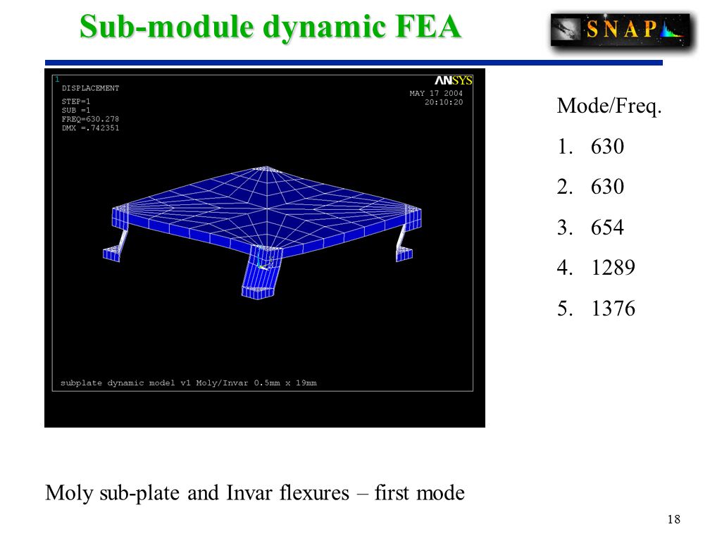
17 Sub-module FEA FE Analyses: Dynamic analysis - vibration modes and frequencies package mass modeled by doubling sub-plate density omit package cutouts, mounting holes, etc. First resonance = 528 Hz for Invar/Invar case First resonance = 630 Hz for Moly/Invar case

18
18 Sub-module dynamic FEA Moly sub-plate and Invar flexures – first mode Mode/Freq. 1.630 2.630 3.654 4.1289 5.1376
19
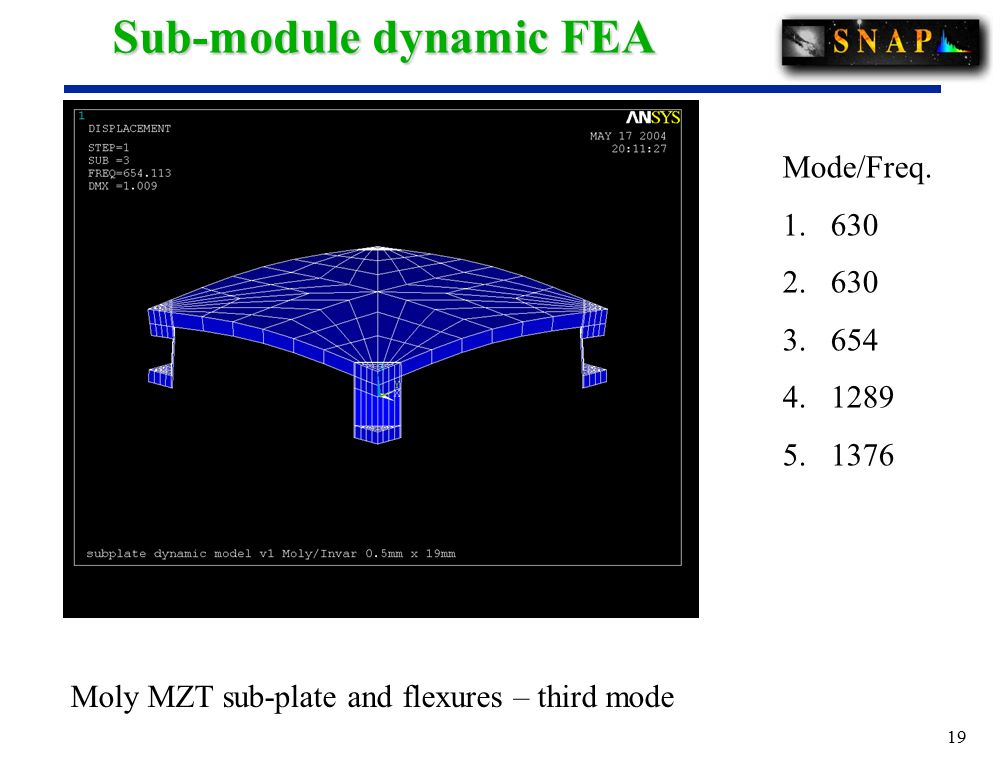
19 Sub-module dynamic FEA Moly MZT sub-plate and flexures – third mode Mode/Freq. 1.630 2.630 3.654 4.1289 5.1376
20
20 Sub-module thermal FEA Thermal analysis – stress and distortion omit package cutouts, mounting holes, etc. omit package mass, stiffness -160 K temperature shift static, isothermal analysis no effort yet to optimize flexure design no effort yet to optimize stiffness of sub-plate

21
21 Sub-module thermal FEA Elements: Purple = Invar Red = Moly

22
22 Sub-module thermal FEA Purple = invar Red = moly Max stress at Invar/Moly joint (not realistic), 86.8 MPa (12,557 Psi), (Invar yield ~ 250 MPa) (Pascals)
, 86.8 MPa (12,557 Psi), (Invar yield ~ 250 MPa) (Pascals)")
23
23 Sub-module thermal FEA Purple = invar Red = moly Shrinkage of Invar vs. Moly in X direction, +/- 50 microns (meters)
.")
24
24 Sub-module thermal FEA Purple = invar Red = moly Shrinkage of Invar vs. Moly in X direction Sub-plate displacement in Z direction – 15 microns (meters)
.")
25
25 Sub-module thermal FEA Purple = invar Red = moly Shrinkage of Invar vs. Moly in X direction Sub-plate displacement in Z direction – 15 microns (meters) Distortion of mounting surface ~2 micron
 Distortion of mounting surface ~2 micron.")
26
26 FP sub-modules Conclusions: sub-module designs for Vis and IR developed detector packages filters with mounts sub-plates sub-plate mounting flexures electrical connectors, junction boxes FEA demonstrates stiffness, high resonant freq. FEA demonstrates acceptable thermal performance

Similar presentations


 1 EddiCam: The Eddington Photometric Camera Preliminary Design Layout.>")

 336-1023.>")

