Download presentation
Presentation is loading. Please wait.

1
GLASS AS EVIDENCE

2
CSI Glass and Light

3
Glass as Evidence

4
FBI’s Steps To Analyzing Glass At A Crime Scene

5
Step 1 Collection and Preservation of Glass

6
The glass fragments should be packaged in solid containers to avoid further breakage. The sample should be collected with consideration being given to the presence of other types of evidence on that sample (e.g., fibers, blood). The collector must consider that fragments within a questioned sample may have multiple origins.
. The collector must consider that fragments within a questioned sample may have multiple origins..")
7
Collection and Preservation of Glass If glass evidence is to be pieced together, all glass must be collected. If no fit can be completed, glass fragments must be submitted with reference samples found at scene. When direction of impact need be determined, all broken glass must be recovered and submitted to the crime lab.

8
Considerations for Collection The glass sample should consist of the largest amount that can be practically collected from each broken object and packaged separately. The sample should be removed from the structure (e.g., window frame, light assembly). When multiple broken glass sources are identified, it is necessary to sample all sources. If the suspect’s shoes and/or clothing are to be examined for the presence of glass fragments, they should be individually wrapped in paper and transmitted to the laboratory.
. When multiple broken glass sources are identified, it is necessary to sample all sources. If the suspect’s shoes and/or clothing are to be examined for the presence of glass fragments, they should be individually wrapped in paper and transmitted to the laboratory..")
10
Step 2 Make your initial examination.

11
If possible, you'll want to determine the color, fluorescence, surface features, curvature, and thickness of the glass.

12
Step 3 Examine Fractures

13
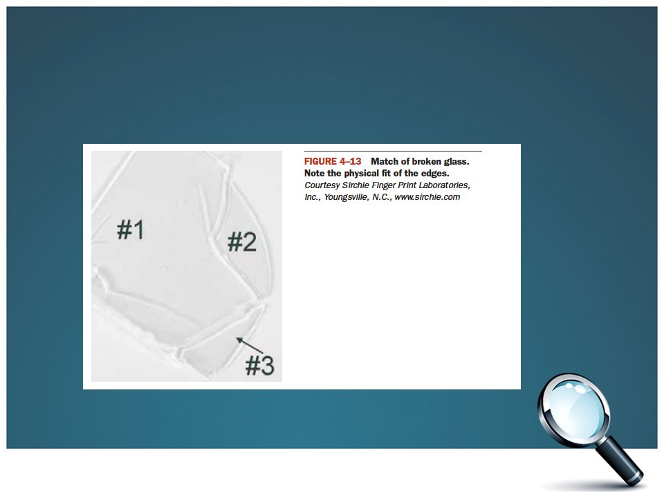
Examine fractures. Are they radial or concentric? Was the glass broken from the inside or the outside? If there are multiple breaks which was first? A fracture match is an absolute means of identification.

14
Fractures Concentric Radial bsapp.com

15
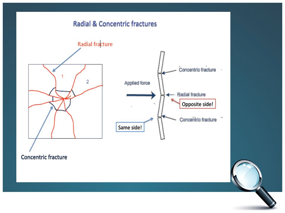
How Does Glass Fracture? Once glass reaches its’ elasticity point, it begins to crack. – Radial fractures develop first on the side opposite of the applied force – The continued motion of the force places tension on the front surface of the glass and results in concentric fractures – Examination of stress marks on the edges of the fractures reveals information related to the side on which the glass first cracked

16
Direction of Penetration Concentric Radial bsapp.com

17
Direction of Penetration A projectile hole is inevitably wider at the exit side bsapp.com

18
Forensic Fracture Analysis

19
Radial Begin at a point and radiate outward from point of impact Initial crack is on the side opposite the applied force

20
Concentric Circular lines around the point of impact Begin on the same side as the force

21
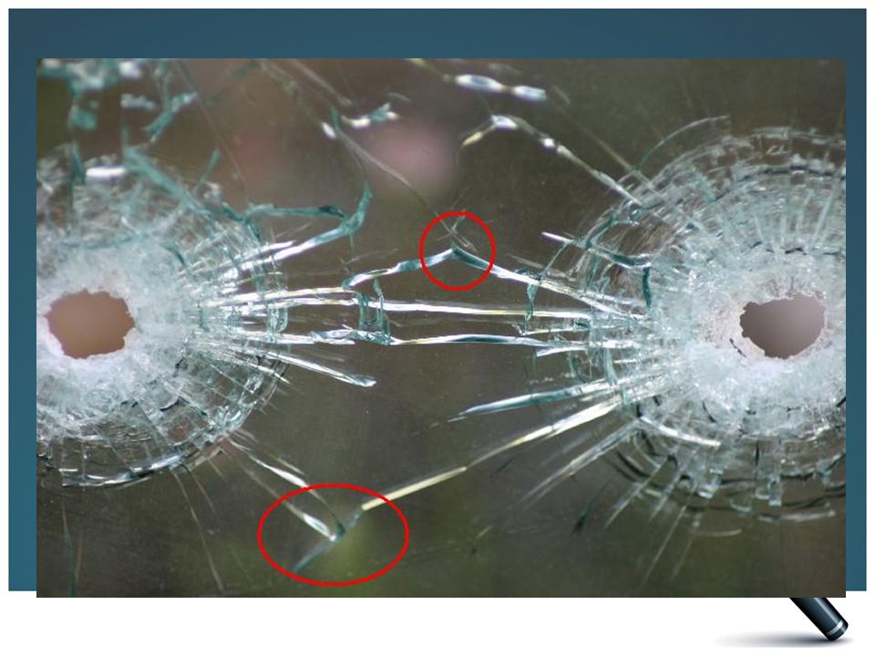
Sequencing A high velocity projectile always leaves a hole wider at the exit side of the glass. Cracks terminate at intersections with others. This can be used to determine the order that the fractures occurred. Kendall/Hunt Publishing Company21

22
Sequencing Which fracture came first? – You can determine the sequence of impacts by observing the existing fracture lines and their points of termination. – A fracture always terminates at an existing line of fracture.

24
Successive Penetrations 1 st 2 nd

25
NOW YOU TRY Which one came first?

26
Practice 2

27
Practice 3

28
Practice 4

29
Stress Markings On Fractures A determination of the direction of force in breaking a window pane: direction of the rib marks [stress marks on broken edges of glass that are perpendicular to one side of glass]
![Stress Markings On Fractures A determination of the direction of force in breaking a window pane: direction of the rib marks [stress marks on broken edges of glass that are perpendicular to one side of glass]](http://images.slideplayer.com/31/9703992/slides/slide_29.jpg "Stress Markings On Fractures A determination of the direction of force in breaking a window pane: direction of the rib marks [stress marks on broken edges of glass that are perpendicular to one side of glass]")
30
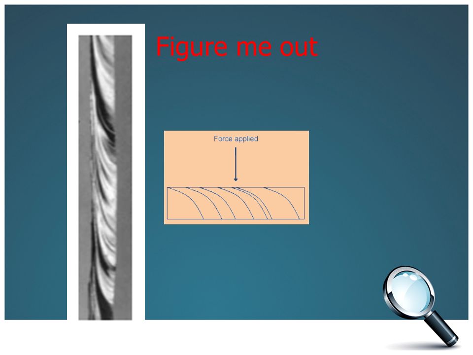
Stress Markings On Fractures Stress marks are shaped like arches that are perpendicular to one glass surface and curved nearly parallel to the opposite surface and are found on radial cracks. The perpendicular end of the arch is always on the side opposite of the impact. 3R Rule: Radial cracks form Right angles on the Reverse side of the force

31
Fracture Patterns 3R rule—radial cracks form a right angle on the reverse side of the force.

33
Figure me out

35
You can use the fractures for Laminated Glass

36
You can’t use the fractures for Tempered Glass

37
Step 4 Measure the Density of the Glass Sample

38
Now measure the density of the glass sample. If glass fragments are too small to be pieced together, they are identified by their densities and refractive indexes. – Only identifies glass to a common source: Class Characteristic Density tells you something about the composition and thermal history of the glass.

39
Method 1: Flotation Method Precise and rapid method for comparing glass densities. Step 1: A glass particle is immersed in a liquid. Step 2: The density of the liquid is carefully adjusted by the addition of small amounts of an appropriate liquid until the glass chip remains suspended in the liquid medium. Step 3: The glass will have the same density as the liquid medium Step 4: The glass can be compared to other relevant pieces of glass which will remain suspended, sink, or float.

40
Method 2: Immersion Method Involves immersing glass particle in water and using the formula for density D=m/v Step 1: Find the mass of the glass particle Step 2: immersing a glass particle in water to get the mass of the water displaced Step 3: Use the mass of the water displaced and the density of water to calculate the volume of water displaced Step 4: The volume of water displaced equals the volume of the glass particle Step 5: Use the mass and volume of the glass particle to determine the density of the glass

41
Density = m/v Type of GlassDensity (g/cm 3 ) window2.46-2.49 headlight2.47-2.63 pyrex2.23-2.36 lead glass2.9-5.9 porcelain2.3-2.5 Kendall/Hunt Publishing Company41
 window headlight pyrex lead glass porcelain Kendall/Hunt Publishing Company41")
42
Step 5 Measure the Refractive Index of the Glass Sample

43
Index of Refractions Demonstrations

44
Measure the refractive index of the glass sample. Refractive index is the most commonly measured property in forensic glass analysis. It can give you the same information as density, but you only need a very small piece of glass. Testing both density and refractive index tells you more than just checking one or the other.

45
RI Variation for Glass Glass shows very little variation in RI Not a conclusive test for source Variation is decreasing with modern manufacturing

46
Decreasing Variation 1964-1997 1980-1997

47
So why use refractive index? For the times that the glass in your sample is “rare” This makes your match more conclusive Example: the glass found in the crime scene is only made by one manufacturer

48
Immersion Method for Refractive Index Refractive index is compared by an immersion method. – Glass particles are immersed in a liquid whose refractive index is varied until it is equal to that of the glass particles. – At this point, called the match point, the observer will note the disappearance of the Becke Line and the glass will seem to disappear. Becke Line: a bright halo that is observed near the border of a particle immersed in a liquid of a different refractive index.

49
The Becke Line The Becke line is a “halo” that can be seen on the inside of the glass on the left, indicating that the glass has a higher refractive index than the liquid medium. The Becke line as seen on the right is outside of the glass, indicating just the opposite.

50
Why do Becke Lines Appear? Becke lines are the result of two things: 1.The fact that glass in thin sections tend to be thicker in the center and thinner towards the edges, thus they act as lenses 2.The indexes of refraction of the glass and the oil are different. This causes the light to bend and form a halo. Both criteria together form Becke lines

51
Becke Lines Becke lines can be found inside or outside of the glass particle Outside Inside The location of the Becke lines depend on the RI of the oil, RI of glass, and the focus of the microscope, whether it is focused up or focused down.

52
Why We See Becke Lines

53
Which Liquid has the closest refractive index?

54
Using a microscope to determine refractive index This occurs in an apparatus called a hot stage which is attached to a microscope. The refractive index of a high boiling liquid, usually a silicone oil, changes with temperature The sample is placed in the oil on the hot stage and the increasing the temperature allows the disappearance of the Becke line to be observed At match point, temperature is noted and refractive index of the liquid is read from a calibration chart

55
Relief When we observe different glass fragments, some stand out more than others. This is known as relief. Relief is an optical property that describes how well a material can be seen and distinguished from its surroundings.

56
Degrees of Relief The greater the difference in refractive index, the more the light is bent and the greater the relief The lower the relief, the closer you are to a match in the refractive index between the glass and the oil.

57
If the immersion medium is changed, the relief will also change When a mineral is immersed in liquids with a different refractive index, its relief will change even if it remains in the same position.

58
Refractive Index LiquidRIGlassRI Water1.333Vitreous silica1.458 Olive oil1.467Headlight1.47-1.49 Glycerin1.473Window1.51-1.52 Castor oil1.82Bottle1.51-1.52 Clove oil1.543Optical1.52-1.53 Bromobenzene1.560Quartz1.544-1.553 Bromoform1.597Lead1.56-1.61 Cinnamon oil1.619Diamond2.419 Kendall/Hunt Publishing Company58

59
Automated Refractive Index Determination What the professionals use.

60
Automated RI Systems GRIM3 – Glass Refractive Index Measurement

61
GRIM measurement technique Silicon oil usually used Oil is calibrated so RI of the oil can be determined from its temperature Sample glass is immersed in oil Oil is heated/cooled to determine match temperature – Point at which the glass “disappears” Oil RI = Glass RI

62
GRIM II identifies the RI match by monitoring a video image of the glass fragment in the liquid -as it is heated/cooled the contrast is measured until a minimum is reached-the match point

64
Step 6 Determine major, minor, and trace elements in the glass

65
Determine major, minor, and trace elements in the glass. These methods are destructive methods so the FBI recommends measuring density and refractive index first Determine the percent of each element in a sample using scanning electron microscopy, X-ray fluorescence spectrometry, inductively coupled plasma-optimal emission spectrophotometry, inductively coupled plasma-mass spectrometry, laser ablation-inductively coupled plasma-mass spectrometry, or atomic absorption spectrophotometry to determine the

66
More on Trace Analysis of Glass Another method results from the fact that glass surface develops unique scratches and abrasions from repeated wear and tear. – For example, the glass windshield of a car might develop tell-tale scratches from wiper blades with embedded grit or other minute objects. These patterns can be used to reconstruct the windshield.

67
How Trace Analysis Can Be Used

68
Extra Slides

69
Forensic Individualization of Glass Types Flat Glass–Soda lime silicate -Rolling or Floating – Tempered: Rapid Cooling Adds Strength Dices when broken Automotive windows & security windows Float Glass floresces when excited at 254 nm.

70
Forensic Individualization of Glass Types – Coated: Surface modification Mirrors – Laminated: Sandwiched around plastic Automotive windshields – Headlights: often borosilicate – Light bulbs: soda lime glass – Heat absorbing/ UV filtering tinting – Eyeglasses: prescription lenses/photosensitive

71
Forensic Individualization of Glass Types Container Glass – Lower magnesium, higher sodium – Clear vs. greenish (window) Glass Fibers – Fiberglass insulation – Alumino-borosilicate – Binder (red or yellow) to hold fibers in bundles
 Glass Fibers – Fiberglass insulation – Alumino-borosilicate – Binder (red or yellow) to hold fibers in bundles.")
Similar presentations


 3.Borosilicate Main component is silicon dioxide (SiO 2 ) which is more commonly referred to as.>")


