Download presentation
Presentation is loading. Please wait.

1
Case Study ARM Platform-based JPEG Codec HW/SW Co-design

2
Outline Introduction to JPEG Codec Review ─ Software ( Concept )
Review ─ Hardware ( Wrapper ) Lab ─ Case study Lab ─ Step and Step Reference
 Lab ─ Case study. Lab ─ Step and Step. Reference.")
3
ISO/IEC 10918-1 JPEG JPEG: Joint Photographic Experts Group
JPEG voted as international standard in 1994 JPEG standard has four compression method Baseline sequential DCT-based coding Progressive DCT-based coding Lossless coding method Sampling and Quantization are not considered at loss-less coding scheme Hierarchical coding method

4
Baseline sequential V.S. Progressive DCT-based coding
Compression Method T I S O 7 3 - 9 / d Baseline sequential V.S. Progressive DCT-based coding

5
Block Diagram of JPEG Encoder
R G B Y Cb Cr … DPCM: Differential Pulse Code Modulation RLC: Run-Length Code

6
Color Model in Video ─ YCrCb
Y: Luminance Cb,Cr: Chrominance YCbCr color model is used in JPEG and MPEG

7
Color Model in Video ─ YCrCb
CCIR-601 transform formula Color space transform is loss-less

8
Chroma Sub-sampling 4:1:1 and 4:2:0 are mostly used in JPEG and MPEG

9
Block Diagram of JPEG Encoder
R G B Y Cb Cr … DPCM: Differential Pulse Code Modulation RLC: Run-Length Code

10
2-D DCT (Discrete Cosine Transform)
Frequency domain Space domain

11
Basis Image of 2-D DCT Horizontal Frequency Vertical Frequency Low
High Vertical Frequency High

12
Frequency Distribution of 2-D DCT
By frequency: By direction:

13
8 point 1-D DCT Algorithm (1/2)
Better for VLSI design implementation!

14
8 point 1-D DCT Algorithm (2/2)
")
15
Implementation 2-D DCT Separable, row-column decomposition X Transport
Memory (Y) Z 1D DCT Unit 1D DCT Unit Y=AX Z=YAT
 Z. 1D DCT. Unit. 1D DCT. Unit. Y=AX. Z=YAT.")
16
Block Diagram of JPEG Encoder
R G B Y Cb Cr … DPCM: Differential Pulse Code Modulation RLC: Run-Length Code

17
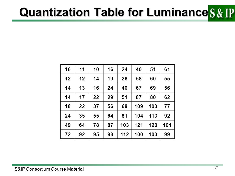
Quantization Table for Luminance
16 11 10 24 40 51 61 12 14 19 26 58 60 55 13 67 69 56 17 22 29 87 80 62 18 37 68 109 103 77 35 64 81 104 113 92 49 78 121 120 101 72 95 98 112 100 99
18
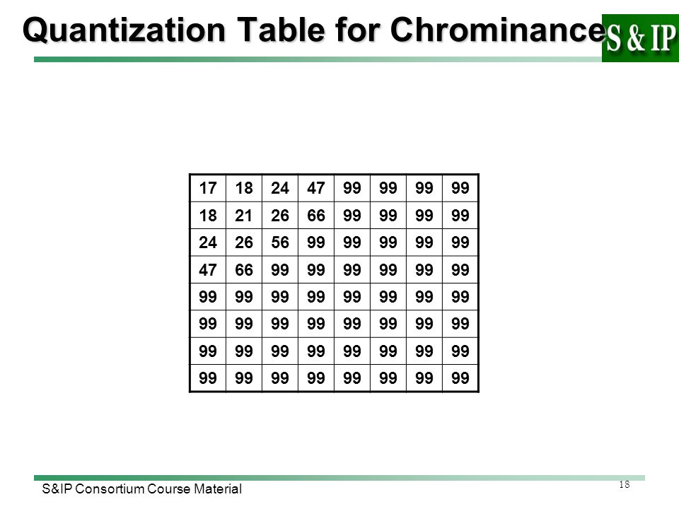
Quantization Table for Chrominance
17 18 24 47 99 21 26 66 56
19
Block Diagram of JPEG Encoder
R G B Y Cb Cr … DPCM: Differential Pulse Code Modulation RLC: Run-Length Code

20
Predictive Coding of DC Coefficients
Differential Pulse Code Modulation (DPCM) To Store the differential value is better than the exact value.
 To Store the differential value is better than the exact value.")
21
Zig-zag Scan (AC Coefficients)
")
22
Run-Length Coding(RLC)
DC (R,L) => (0,-3)(0,-2)(0,-1)(0,-2)(0,-1)(2,-1)(EOB)
 => (0,-3)(0,-2)(0,-1)(0,-2)(0,-1)(2,-1)(EOB)")
23
Huffman Coding (R,L) => (0,-3)(0,-2)(0,-1)(0,-2)(0,-1)(2,-1)(EOB)
Category AC Coefficient Range 1 -1,1 2 -3,-2,2,3 3 -7,…,-4,4,…,7 4 -15,…,-8,8,…,15 5 -31,…,-16,16,…,31 6 -63,…,-32,32,…,63 7 -127,…,-64,64,…,127 8 -255,…,-128,128,…,255 9 -511,…,-256,256,…,511 10 -1023,…,-512,512,…,1023 11 -2047,…,-1024,1024,…,2047 (0,2)(-3),(0,2)(-2),(0,1)(-1),(0,2)(-2),…(0,0) (Run,SSSS/Catagory) Huffman Table
(-3),(0,2)(-2),(0,1)(-1),(0,2)(-2),…(0,0) (Run,SSSS/Catagory) Huffman Table.")
24
Huffman Coding for DC and AC Coefficient
Run/Size Code length Code word 0/0 (EOB) 14 1010 0/1 12 00 0/2 01 0/3 13 100 0/4 1011 0/5 15 11010 0/6 17 0/7 18 0/8 10 0/9 16 0/A 1/1 1100 1/2 11011 1/3 1/4 19 Category Code length Code word 10 2 000 11 3 010 12 011 13 100 14 101 15 110 16 4 1110 17 5 11110 18 6 111110 19 7 8 9 Table for luminance DC coefficient differences Table for luminance AC coefficients (0,2)(3),(0,2)(-2),(0,1)(-1),(0,2)(-2),…(0,0) =>(01) (11) (01) (01) ……(1010)
 / / / / / / / / / /A / / / / Category. Code length. Code word Table for luminance DC coefficient differences. Table for luminance AC coefficients. (0,2)(3),(0,2)(-2),(0,1)(-1),(0,2)(-2),…(0,0) =>(01) (11) (01) (01) ……(1010)")
25
Example of Baseline DCT-based Coding
For Y, (8*8 pixels *8 bits/pixel = 512 bits) FDCT -128 Q (6)(61),(0,2)(-3), (0,3)(4),(0,1)(-1), (0,3)(-4),(0,2)(2), (1,2)(2),(0,2)(-2), (0,2)(-2),(5,2)(2), (3,1)(1),(6,1)(-1), (2,1)(-1),(4,1)(-1), (7,1)(-1),(0,0) Zig-Zag (1110)(111101)(01)(00)(100) (100)(00)(0)(100)(001)(01) (10)(11011)(10)(01)(01)(01) (01)( )(10)(111010)(1)( )(0)(11100)(0) (111011)(0)( )(0)(1010) Huffman Run-length total 102 bits Q Table
 FDCT Q. (6)(61),(0,2)(-3), (0,3)(4),(0,1)(-1), (0,3)(-4),(0,2)(2), (1,2)(2),(0,2)(-2), (0,2)(-2),(5,2)(2), (3,1)(1),(6,1)(-1), (2,1)(-1),(4,1)(-1), (7,1)(-1),(0,0) Zig-Zag. (1110)(111101)(01)(00)(100) (100)(00)(0)(100)(001)(01) (10)(11011)(10)(01)(01)(01) (01)( )(10)(111010)(1)( )(0)(11100)(0) (111011)(0)( )(0)(1010) Huffman. Run-length. total 102 bits. Q Table.")
26
Block Diagram of JPEG Encoder
R G B Y Cb Cr … DPCM: Differential Pulse Code Modulation RLC: Run-Length Code

27
Block Diagram of JPEG Decoder
…

28
JPEG Bitstream

29
Outline Introduction to JPEG Codec Review ─ Software ( Concept )
Review ─ Hardware ( Wrapper ) Lab ─ Case study Lab ─ Step and Step Reference
 Lab ─ Case study. Lab ─ Step and Step. Reference.")
30
Review Process run Linker Tailoring the C library
Load and Execution View

31
Process Run

32
Stack Function parameter Local variable

33
Heap malloc() new operator
 new operator")
34
Linker

35
ARM Linker Control File

36
Linker

37
Tailoring the C Library
The management of writable memory as static data, heap and stack Functions that can be redefined Redirection I/O function

38
Memory Model Single memory region
The stack grows downward from the top of memory The heap grows upwards from the bottom of the region

39
Single Memory Model

40
Controlling Runtime Memory Model
Function Description __user_initial_stackheap() Return the location of the initial heap __user_heap_extend() Returns the size and base address of a heap extra block __user_stack_slop Returns the amount of extra stack
 Return the location of the initial heap. __user_heap_extend() Returns the size and base address of a heap extra block. __user_stack_slop. Returns the amount of extra stack.")
41
My Own Memory Model Function Description __rt_stackheap_init()
It is responsible for setting up sp and sl to point a valid stack __rt_stack_overflow() It is called if a stack overflow occurs __rt_heap_extend() This function returns a new 8-byte aligned block
 It is called if a stack overflow occurs. __rt_heap_extend() This function returns a new 8-byte aligned block.")
42
Trailing the I/O Function

43
Load View and Execution View

44
Outline Introduction to JPEG Codec Review ─ Software ( Concept )
Review ─ Hardware ( Wrapper ) Lab ─ Case study Lab ─ Step and Step Reference
 Lab ─ Case study. Lab ─ Step and Step. Reference.")
45
AHB Protocol

46
AHB Wrapper

47
Input Pin Block Diagram

48
Output Pin Block Diagram

49
Outline Introduction to JPEG Codec Review ─ Software ( Concept )
Review ─ Hardware ( Wrapper ) Lab ─ Case study Lab ─ Step and Step Reference
 Lab ─ Case study. Lab ─ Step and Step. Reference.")
50
Lab ─ Case Study Goal Principles Requirement Discussion
Implement the JPEG codec system using ARM platform Principles Implement the ARM platform-based JPEG codec HW/SW co-design Requirement Analysis the profiling of pure software simulation Explain how to partition the HW/SW of JPEG codec Implement the JPEG codec with HW/SW co-design Discussion Explain where is the stack and heap ? And who initialize them

51
File Structure

52
Read & Write Address FDCT IDCT Write_head 0xcc000000 0xcc000004
0xcc00000c 0xcc000010 0xcc000014 0xcc000018 0xcc00001c Write_head 0xcc000040 0xcc000044 0xcc000048 0xcc00004c 0xcc000050 0xcc000054 0xcc000058 0xcc00005c FDCT IDCT Read_head 0xcc000020 0xcc000024 0xcc000028 0xcc00002c 0xcc000030 0xcc000034 0xcc000038 0xcc00003c Read_head 0xcc000060 0xcc000064 0xcc000068 0xcc00006c 0xcc000070 0xcc000074 0xcc000078 0xcc00007c

53
Result for SW Simulation
Original Encoder Decoder

54
Result for HW Simulation
Original Encoder Decoder

55
Profiling Result of SW Simulation

56
Outline Introduction to JPEG Codec Review ─ Software ( Concept )
Review ─ Hardware ( Wrapper ) Lab ─ Case study Lab ─ Step and Step Reference
 Lab ─ Case study. Lab ─ Step and Step. Reference.")
57
Step 1 (Only Software) 首先,請先確定工作目錄。例如:D:\ARMSoC\Final_project\
請確定工作目錄下是否有sw.bat此批次檔

58
Step 2 (Only Software) 執行sw.bat此批次檔。方法有二:第一是直接在sw.bat此批次檔的圖示上按滑鼠左鍵兩下即可﹔第二個方法是在命令提示字元視窗下,進入工作目錄後,鍵入sw.bat
 執行sw.bat此批次檔。方法有二:第一是直接在sw.bat此批次檔的圖示上按滑鼠左鍵兩下即可﹔第二個方法是在命令提示字元視窗下,進入工作目錄後,鍵入sw.bat.")
59
Step 3 (Only Software) 開啟AXD Debugger的視窗 選擇〝File → Load Image
選擇〝Execute → Go〞

60
Step 1 ( SW/HW ) 確定工作目錄。例如:D:\ARMSoC\Final_project\
 確定工作目錄。例如:D:\ARMSoC\Final_project\")
61
Step 1 ( SW/HW ) 利用Xilinx ISE軟體將提供之Verilog HDL碼編譯為可燒錄之*.bit檔
 利用Xilinx ISE軟體將提供之Verilog HDL碼編譯為可燒錄之*.bit檔")
62
Step 2 ( SW/HW ) 將ahbahbtop.bit檔燒錄至ARM Integrator之LM模組上
在燒錄時需要Download.brd以及LM_flash_load.bit此二檔案

63
Step 3 ( SW/HW ) 執行hw.bat此批次檔 批次檔執行結束之後,確定工作目錄中是否產生了hw.axf檔案
 執行hw.bat此批次檔 批次檔執行結束之後,確定工作目錄中是否產生了hw.axf檔案")
64
Step 4 ( SW/HW ) 開啟AXD Debugger的視窗 選擇〝File → Load Image〞
選擇〝Execute → Go〞

65
Outline Introduction to JPEG Codec Review ─ Software ( Concept )
Review ─ Hardware ( Wrapper ) Lab ─ Case study Lab ─ Step and Step Reference
 Lab ─ Case study. Lab ─ Step and Step. Reference.")
66
Reference Wen-Hsiung Chen, C. Harrison Smith, and S. C. Fralick, "A Fast Computational Algorithm for the Discrete Cosine Transform," IEEE Trans. Commun., vol. COM-25, pp , Sept 1977. JPEG: Still Image Data Compression Standard by William B. Pennebaker and Joan L. Mitchell, Kluwer Academic Publishers, ISBN:

Similar presentations


.>")


 elm IE Outlook Express Netscape 傳訊者 通訊錄管理.>")


 ;另一種則是內建元 件庫 (Common Libraries), 兩者皆可透過 『視窗』功能表來開啟, 以下即為您說明。>")


 Coding and Processing Lecture: DCT Compression and JPEG Wade Trappe Again: Thanks to Min Wu for allowing me to borrow many of her slides.>")
 Ketan Mayer-Patel.>")