Download presentation
Presentation is loading. Please wait.

1
ME16A: CHAPTER FOUR ANALYSIS OF STRESSES IN TWO DIMENSIONS

2
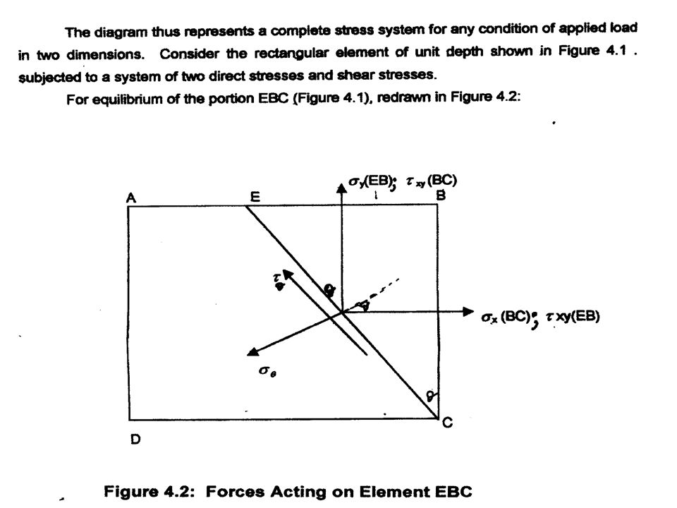
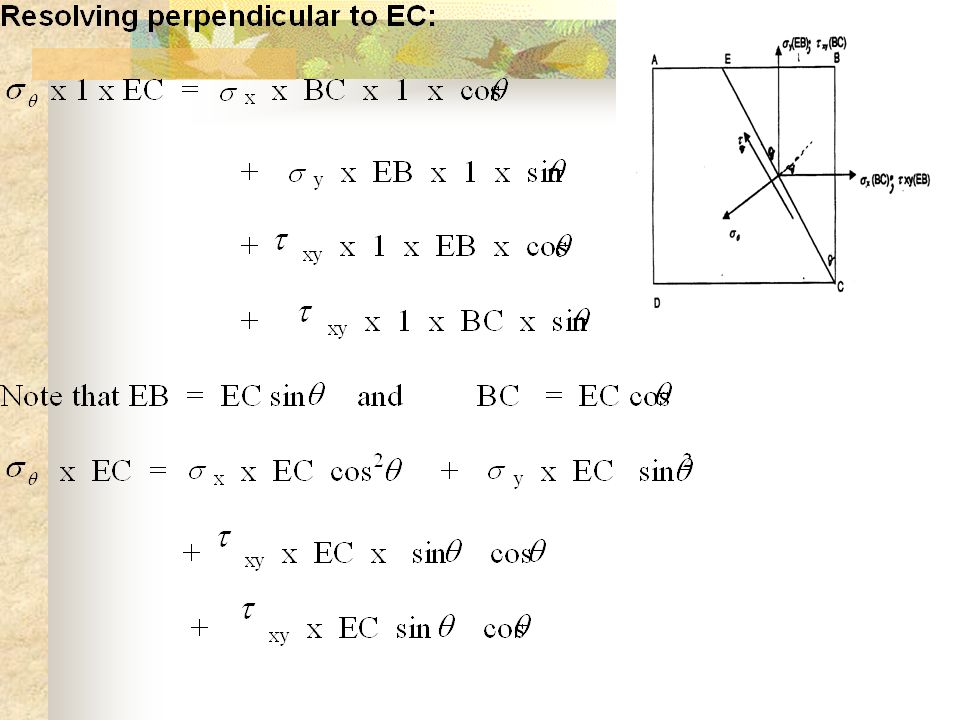
4.1 DERIVATION OF GENERAL EQUATIONS

6
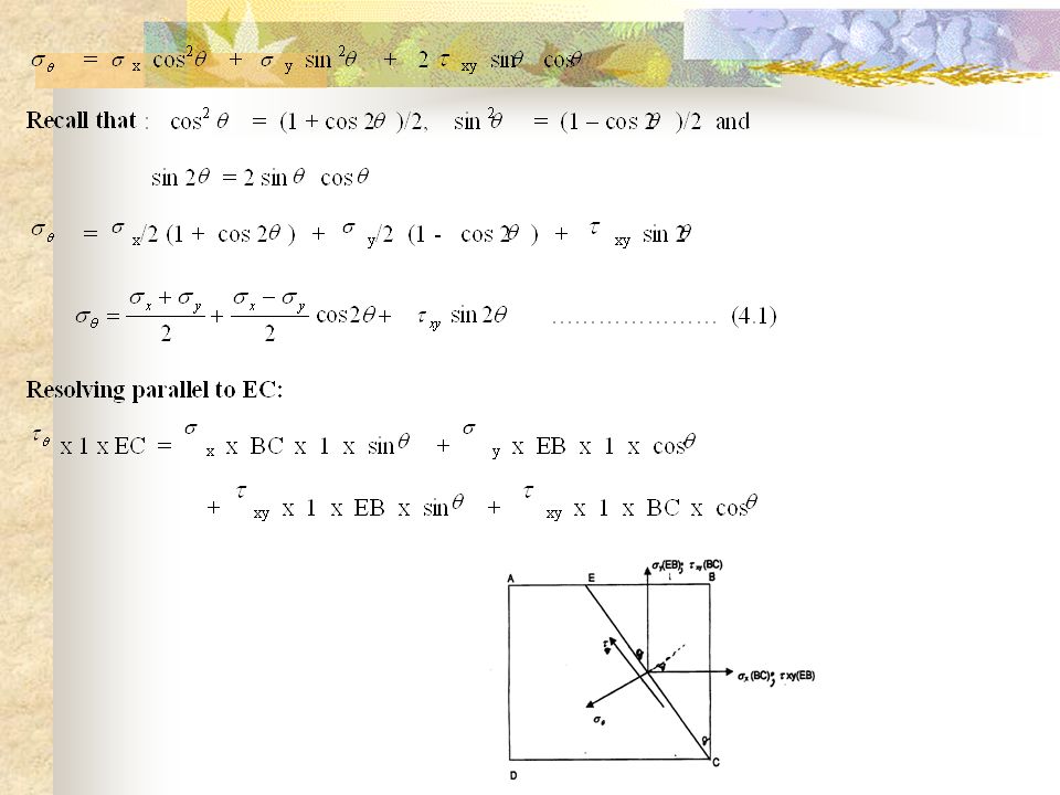
Derivation of General Equation Concluded

7
SPECIAL CASES OF PLANE STRESS

8
Special Cases of Plane Stress Contd.

9
Maximum Shear Stress

10
Example

11
Solution

12
Principal Stresses and Maximum Shear Stresses

13
Principal Stresses and Maximum Shear Stresses Contd.

14
Shear Stresses at Principal Planes are Zero

15
Principal Planes and Stresses Contd.

16
Equation For Maximum Shear Stress

17
4.4 PRINCIPAL PLANE INCLINATION IN TERMS OF THE ASSOCIATED PRINCIPAL STRESS

18
PRINCIPAL PLANE INCLINATION CONTD. Consider once again the equilibrium of a triangular block of material of unit depth (Fig. 4.3); this time EC is a principal plane on which a principal stress acts, and the shear stress is zero (from the property of principal planes).
; this time EC is a principal plane on which a principal stress acts, and the shear stress is zero (from the property of principal planes)..")
19
PRINCIPAL PLANE INCLINATION CONTD. Resolving forces horizontally, (, x x BC x 1) + ( xy x EB x 1)= ( p xEC x l) cos x EC cos + xy x EC sin = p xECcos x + xy tan = p px xy … (4.7) E
 + ( xy x EB x 1)= ( p xEC x l) cos x EC cos + xy x EC sin = p xECcos x + xy tan = p px xy … (4.7) E.")
20
PRINCIPAL PLANE INCLINATION CONTD. Thus we have an equation for the inclination of the principal planes in terms of the principal stress. If, therefore, the principal stresses are determined and substituted in the above equation, each will give the corresponding angle of the plane on which it acts and there can then be no confusion.

21
PRINCIPAL PLANE INCLINATION CONTD. The above formula has been derived with two tensile direct stresses and a shear stress system, as shown in the figure; should any of these be reversed in action, then the appropriate minus sign must be inserted in the equation.

22
Graphical Solution Using the Mohr’s Stress Circle

23
Mohr’s Circle Contd. Direct stresses: tensile, positive; compressive, negative; Shear stresses: tending to turn block clockwise, positive; tending to turn block counterclockwise, negative. This gives two points on the graph which may then be labeled AB and BC respectively to denote stresses on these planes

24
Mohr’s Circle Contd. A B CD

25
Fig. 4.5 Mohr's stress circle.

26
Proof

27
Proof Contd.

28
Note

29
Further Notes on Mohr’s Circle

30
Further Notes on Mohr Circle Contd.

31
Preference of Mohr Circle The graphical method of solution of complex stress problems using Mohr's circle is a very powerful technique since all the information relating to any plane within the stressed element is contained in the single construction. It thus provides a convenient and rapid means of solution which is less prone to arithmetical errors and is highly recommended.

Similar presentations

 Spring 2008>")

 The load, the shock,>")


 Spring 2008 Dr. Konstantinos A. Sierros.>")
 Is there any general method to determine stresses on any arbitrary.>")


>")


