Download presentation
Presentation is loading. Please wait.

1
Neutrino Detection at the South Pole: Instrumentation Issues Dr. Steve Churchwell University of Canterbury, Christchurch, New Zealand The RICE detector and DAQ: Present and Future

2
Outline Physics interest (why detect neutrinos?) Existing RICE detector and DAQ systems New DAQ system with in-ice digitization Plans for the next few years
 Existing RICE detector and DAQ systems New DAQ system with in-ice digitization Plans for the next few years")
3
Physics Interest (why are we interested in high energy neutrinos?) Expect neutrinos from Active Galactic Nuclei (AGN – formerly QUASARS) Expect neutrinos from Gamma Ray Bursters (GRBs) Origins of ultra high energy cosmic rays not understood Neutrinos can travel through regions opaque to other forms of radiation (eg the galactic center) Neutrinos unaffected by magnetic fields so they point back to their source the same as photons – but unlike charged cosmic rays
 Expect neutrinos from Active Galactic Nuclei (AGN – formerly QUASARS) Expect neutrinos from Gamma Ray Bursters (GRBs) Origins of ultra high energy cosmic rays not understood Neutrinos can travel through regions opaque to other forms of radiation (eg the galactic center) Neutrinos unaffected by magnetic fields so they point back to their source the same as photons – but unlike charged cosmic rays")
4
Why the South Pole? Largest, purest uniform block of material on earth Easier than sea water!!! Existing Station and Infrastructure Minimal though it is Other neutrino / cosmic ray experiments already there Relatively noise free RF environment No TV, Radio, cell phones, RADAR, etc

5
Askaryan Effect Coherent cerenkov radiation at long wavelengths relative to shower dimensions As shower progresses a negative charge excess develops Atomic electrons are “swept” into shower by shower particles Positrons are annihilated Excess is about 30% Showers typically extend about 10-15cm radially, so wavelengths longer than This will be coherently radiated (30cm = 700 MHz in ice) Field strength of cherenkov radiation scales with number of particles Sensitive only to very large showers (10 15 eV and higher)
 Field strength of cherenkov radiation scales with number of particles Sensitive only to very large showers (10 15 eV and higher)")
6
Existing RICE Detectors 5 km 300m

7
Antennas Stubby Dipole (shown below) Designed for 300 MHz center freq Investigating other shapes such as Bicones Helical Dipoles Horns used on surface Limited by bore hole size (often only 6-8 inches diameter)
 Designed for 300 MHz center freq Investigating other shapes such as Bicones Helical Dipoles Horns used on surface Limited by bore hole size (often only 6-8 inches diameter)")
8
Existing RICE Electronics

9
Triggers Require at least 4 coincident antennae to reconstruct Cherenkov cone Coincidence defined as overlap within 1.2 us window Allow for external triggers (eg from AMANDA or SPASE) Surface antennas act as “Vetoes” (inhibit trigger)
 Surface antennas act as Vetoes (inhibit trigger)")
10
From: Saltzberg et al, Phys Rev E 62, 8590 (2000) Expected Waveforms
 Expected Waveforms")
12
Scaling up for a larger Experiment Have not detected any high energy neutrinos yet (don't really expect to based on predicted rates for small volume experiment) Need to increase instrumented volume considerably Would like to place receivers over IceCube detector (1 km 2 ) - Hope to deploy about 100 new antennas Problems: Cost: Coax cable is noisy and lossy Scopes are over-kill and expensive ($2500/channel) Coax costs $5/m (USD) Current system can’t scale much larger!
 Need to increase instrumented volume considerably Would like to place receivers over IceCube detector (1 km 2 ) - Hope to deploy about 100 new antennas Problems: Cost: Coax cable is noisy and lossy Scopes are over-kill and expensive ($2500/channel) Coax costs $5/m (USD) Current system can’t scale much larger!")
13
In-Ice Digitization Solve coax problem by digitizing RF signal at antenna rather than at the surface. Fast ADCs are cheap – 1Gsps, 8 bits, $500 or less Have to design our own electronics boards around these devices -50C High pressure Inaccessible Small volume low power Use “cheap” digital communication between surface and digitizer Twisted pair (CAT5) or Optical About $1/m
 or Optical About $1/m.")
14
In-ice digitization should improve noise characteristics Uses few mW of power Has analog BW up to 3 GHz takes 256 samples at trigger (trigger position definable within sample window) Consists of array of switched capacitors (sample and holds) Analog waveform can be stored for many s before being digitized May allow trigger decision to be made before actually digitizing waveform No dispersion in coax No attenuation in coax Digitization Benefits Rather than continuous digitization, use triggered system designed at Univ. of Hawaii. STRAW – (Self Triggered Recorder of Analog Waveforms)
.")
15
(From Gary Varner)
")
17
Timing Requirements for Distributed System Use time-of-flight to track radio pulses back to interaction vertex 10 ns corresponds to about 2m position uncertainty Can't use GPS: (30-50 ns resolution at best) Even 10 ppb clocks will drift by 10 ns every second!!! Need PLL system from central high stability clock Even if central clock drifts, all remote clocks should track it Requires separate connection for timing signals. Plan to use CAT5 twisted pair Can send 100V DC power on same cable to power remote system Since PLL – can send few kHz clock signal to run 100 MHz clock

18
Better timing from 50 MHz clock Have 16 RF input channels on STRAW chip, expect 2-4 local antennas/digitizer, so can easily digitize additional signals Need to calibrate final system using RF pulsers on the surface Need pulsers in several locations (serially) to also determine final antenna locations accurately Slope ambiguity can be removed by digitizing clock as well Can also simply count transitions and distinguish even from odd
 to also determine final antenna locations accurately Slope ambiguity can be removed by digitizing clock as well Can also simply count transitions and distinguish even from odd")
19
Problems with Remote Triggering ● Noise rates are fairly high (aim for about 1 kHz singles rates) ● Only method to limit trigger rates is coincidence ● Coincidences can only be found after all triggered digitizers have reported to the central system Place multiple antennas close together (local coincidence) Should limit thermal noise Note: most noise is not thermal
 ● Only method to limit trigger rates is coincidence ● Coincidences can only be found after all triggered digitizers have reported to the central system Place multiple antennas close together (local coincidence) Should limit thermal noise Note: most noise is not thermal")
21
Problems with Remote Triggering ● Noise rates are fairly high (aim for about 1 kHz singles rates) ● Only method to limit trigger rates is coincidence ● Coincidences can only be found after all triggered digitizers have reported to the central system Place multiple antennas close together (local coincidence) Should limit thermal noise Send only timing info to triggering system and buffer waveform data until requested Note: most noise is not thermal
 ● Only method to limit trigger rates is coincidence ● Coincidences can only be found after all triggered digitizers have reported to the central system Place multiple antennas close together (local coincidence) Should limit thermal noise Send only timing info to triggering system and buffer waveform data until requested Note: most noise is not thermal")
22
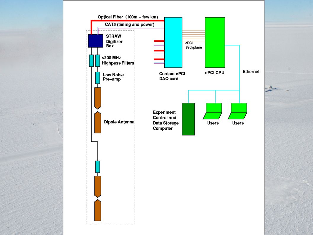
Central DAQ System Currently designing around cPCI (Cheap, fast, reliable, lots of existing hard- and software) Designing custom DAQ cards which will communicate with the in-ice digitizers. Will also distribute the timing pulses and DC power Cards will interact with cPCI CPU via backplane and can generate hardware interrupts so triggering decisions can by made by CPU All modern cPCI cpus come with fast ethernet, so data storage will be on a separate “normal” PC. Should be able to “log” the data from anywhere.

24
University of Canterbury Contribution ● Simulations (same for IceCube) – GEANT4; PYTHIA ● Surface DAQ system – Design – Prototype – Build – Programming Timing Data Analysis Deployment
 – GEANT4; PYTHIA ● Surface DAQ system – Design – Prototype – Build – Programming Timing Data Analysis Deployment")
25
Funding US: NSF grants Have generally piggybacked on top of AMANDA (pays for logistical support at the pole) Canterbury: Marsden grant from 2001-2003 (Jenni Adams) Currently doing hardware development with very minimal UC internal grant Simulations don’t cost anything Need to extend our funding for more R&D and Travel – let US NSF pay for manufacturing final systems
 Canterbury: Marsden grant from (Jenni Adams) Currently doing hardware development with very minimal UC internal grant Simulations don’t cost anything Need to extend our funding for more R&D and Travel – let US NSF pay for manufacturing final systems")
26
Plans Finish prototype digitizer and cPCI DAQ card designs (Now until Dec/Jan) Install new system in parallel with existing system inside the counting house (surface, warm, accessible...) (Jan 2005) Compare results for 1 season Apply improvements and start deploying additional antennas (start early 2005) Begin deploying new system with new antennas – hopefully in IceCube holes starting 2005/2006 season
 Install new system in parallel with existing system inside the counting house (surface, warm, accessible...) (Jan 2005) Compare results for 1 season Apply improvements and start deploying additional antennas (start early 2005) Begin deploying new system with new antennas – hopefully in IceCube holes starting 2005/2006 season")
Similar presentations


 – Secondaries (pions) – Decay products (muons, photons, electrons)>")


 KM3Net Kick-off Meeting, Erlangen-Nuremberg,>")


 Center for Remote Sensing of Ice Sheets, University of Kansas, Lawrence, KS 66045.>")