Download presentation
Presentation is loading. Please wait.

1
Introduction to Nanoscan

2
Introduction to NanoScan
What is a NanoScan? How does it work What it measures Different NanoScan flavors Different Hardware How to sell a NanoScan What customers to go after Matching the application to the NanoScan Using the relevant charts Application Examples and Tips Real examples of focused spot measurements

3
How does it work?

4
Beam Sampling Technique

5
Beam Sampling Technique

6
Slit Scanner Operation

7
What the data looks like

8
What parameters does a NanoScan measure?
Beam size Beam position Beam ellipticity Gaussian fit Beam Divergence Power (yes, power!)
")
9
Beam Width, Clip Level Method
Laser Beam Profile Centroid 100% Irradiance FWHM 13.5% (1/e2) Distance Across Beam Irradiance = Power/unit area
 Distance Across Beam. Irradiance = Power/unit area.")
10
Beam Width 4-Sigma Measurement
4-sigma measurement points

11
Measures most Wavelengths

12
NanoScan Scan Heads Silicon Detector (visible λ)
λ =190 to 900 nm Not recommended for wavelengths > 1000 nm 10 μm to 20 mm spot size range Germanium Detector (near IR λ) λ =700 to 1800 nm 10 μm to 12 mm spot size range Pyroelectric Detector λ =0.25 to 20 μm including 10.6 μm 20 μm to 20 mm spot size range
 λ =700 to 1800 nm. 10 μm to 12 mm spot size range. Pyroelectric Detector. λ =0.25 to 20 μm including 10.6 μm. 20 μm to 20 mm spot size range.")
13
NanoScan Configurations
Pyroelectric Heads has 9 mm aperture and 5 micron slits Silicon and Germanium Heads have 2 Apertures—3.5mm, 9mm 3.5 mm Aperture has 1.8μm Slit Size 9 mm Aperture has 5 microns Large Aperture Heads 25mm for Si, 20mm for Pyro, 12mm for Ge Slits 25μm

14
NanoScan Hardware History
Photon launched the BeamScan in 1984, a completely analog product. Computer controller systems developed in the 90’s. Ophir can verify calibration of existing BeamScan systems, but can no longer make repairs or adjustments. (BeamScan 0180 ISA controller card pictured right.) NanoScan released at Photonics West Conference, 2003.
 NanoScan released at Photonics West Conference,")
15
NanoScan Hardware History
2003: Original NanoScan used a PCI card wich is no longer available. 2008: Photon introduced USB Controller Box (these systems only licensed with versions 1.47 or 2.1 software) “NanoScan I”
 NanoScan I")
16
NanoScan Hardware History
2013: Ophir launches the NanoScan II. Direct to USB interface, 3.5 and 9.0 mm apertures only (these systems work with version 2.3 or later software)
")
17
What are the NanoScan’s strengths?
Small beams (10 microns and larger) Easy-to-use (just shine the light in the hole) Requires less beam attenuation, and in many applications, no beam attenuation than cameras Measurement plane easily defined Often provides better accuracy and is the lower priced option in the IR and NIR Measures changing beam sizes very quickly, important for optical alignment, M2 measurements
 Easy-to-use (just shine the light in the hole) Requires less beam attenuation, and in many applications, no beam attenuation than cameras. Measurement plane easily defined. Often provides better accuracy and is the lower priced option in the IR and NIR. Measures changing beam sizes very quickly, important for optical alignment, M2 measurements.")
18
Slit Plane Well-defined

19
Competitive Advantage in the NIR, IR
Germanium NanoScan vs. InGaAs camera ( nm) Cost: ~$5,000-$6,000 USD vs $25,000 USD Smallest measureable beam size: 20 micron vs microns Pyroelectric NanoScan vs. Pyrocam $9,000-$11,000 USD vs. $23,000-$30,000 USB 20 microns vs. ~ 1 mm
 Cost: ~$5,000-$6,000 USD vs $25,000 USD. Smallest measureable beam size: 20 micron vs. 500 microns. Pyroelectric NanoScan vs. Pyrocam. $9,000-$11,000 USD vs. $23,000-$30,000 USB. 20 microns vs. ~ 1 mm.")
20
Changing beam sizes If the beam size changes from 1 mm to 100 microns, with a CCD, you’ll need to: Add a neutral density filter into the beam path (~30 seconds) Change the camera integration time (~30 seconds) Perform an Ultracal (~10 seconds) With a NanoScan, you don’t have to do anything! The amplification gain changes automatically in under a second
 Change the camera integration time (~30 seconds) Perform an Ultracal (~10 seconds) With a NanoScan, you don’t have to do anything! The amplification gain changes automatically in under a second.")
21
Where a NanoScan has weaknesses
Pulsed beams under 1 kHz not measured at all, and many small beam size applications under 10 kHz not measured very well Highly multimode beams (spatial resolution is lost due to averaging of all the light passing through the slit)
")
22
The 2D/3D windows are not data!!!!
The 1-D slit profiles are the data 2D/3D profiles are visualizations of the slit profile data This visualization can and will create features that are not actually in the beam Customers requested this feature to help them intuitively understand the beam The NanoScan is NOT a camera

23
How to sell a NanoScan Who are the customers to go after? Matching the customer application to the right model Using the operating space chart Making sure the beam won’t damage the slits Pulsed beam applications

24
Who are the customers to go after?
Historically, NanoScans have sold in volume to customers involved with: Fiber optic components Laser printing Bar code scanners Flow cytometry Semiconductor applications where small beam sizes are involved Intermediate power applications (1-100 Watts) where a CCD profiler would require a lot of complication beam attenuation
 where a CCD profiler would require a lot of complication beam attenuation.")
25
Four and a half questions to ask a customer
What is the wavelength? (determines the sensor) What is the beam size? (determines the slit and aperture) What is the beam power? (determines the detector Si/Ge or Pyro) Is the beam continuous or pulsed? If pulsed, what is the rep rate? (whether or not the NanoScan is a solution)
 What is the beam size (determines the slit and aperture) What is the beam power (determines the detector Si/Ge or Pyro) Is the beam continuous or pulsed If pulsed, what is the rep rate (whether or not the NanoScan is a solution)")
26
Use the Operating Space Charts

27
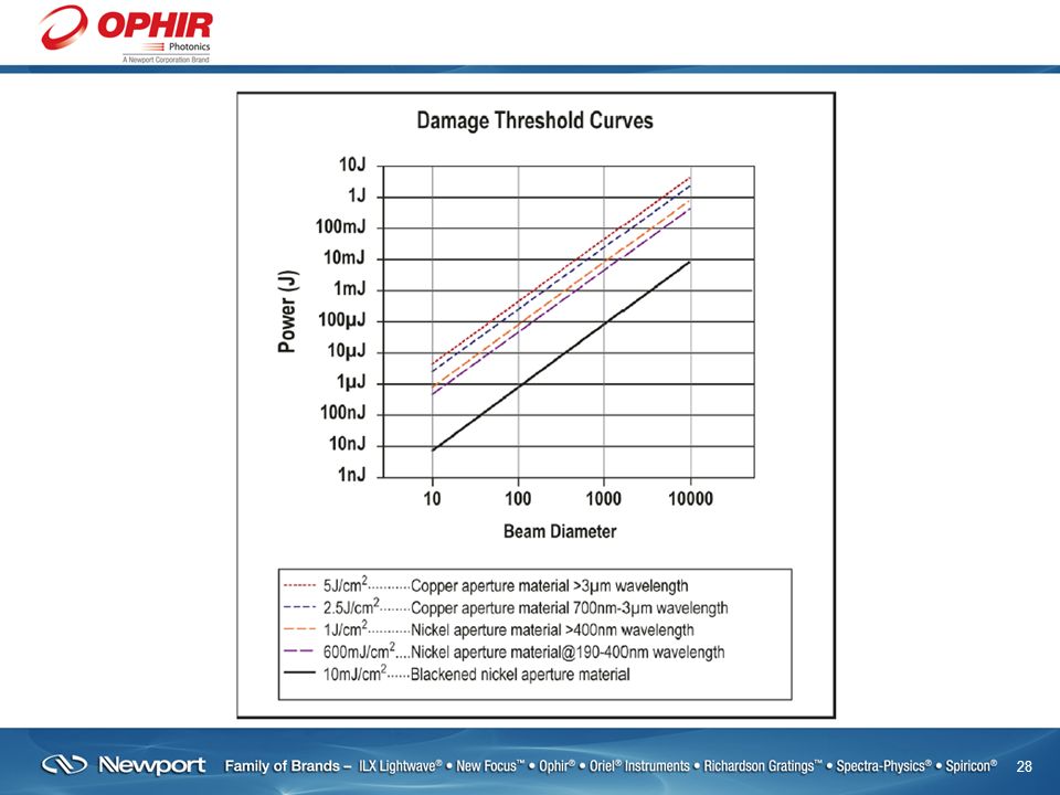
High Power Application
To make sure the beam under test does not damage the NanoScan slits, need to consider the beam size, average beam power, and laser repetition rate very carefully.

29
Damage Thresholds 1J/cm2—Ni Slits at >400nm
600mJ/cm2—Ni Slits at 190nm-400nm 10mJ/cm2—Blackened slit material Pyroelectric NanoScans use reflective Ni slits. Si and Ge NanoScans use blackened Ni slits. Copper (Cu) no longer available due to difficulties with the Cu material (In certain applications, unblackened Ni slits are used in Si or Ge NanoScans)
 no longer available due to difficulties with the Cu material. (In certain applications, unblackened Ni slits are used in Si or Ge NanoScans)")
30
NanoScan Exposure Limit Calculator

31
Measuring Pulsed Beams
You can think of each pulse of the laser to be a single point in the profile. So faster pulse rates lead more profile data points, and the slower the slit passes through the beam, the more data points can be taken. To get a reliable beam size, you need at least 15 points in the profile.

32
Repetition Frequency vs Beam Size

33
Pulse Rate vs. Beam Size Use this table to determine the correct rotation speed to set the NanoScan to for the pulse rate and beam size being measured

34
A general rule of thumb for pulsed beams….
Laser rep rates over 500 kHz can be treated as continuous when using the NanoScan. For beam sizes > 1mm, 300 kHz and higher rep rates can also be treated as continuous.

35
Pulsed Beams With pulsed mode turned off, a pulsed laser has a “picket fence” profile.

36
Pulsed Mode On Peak Connect in pulsed mode extracts the profile from the picket fence Very important to input the correct laser rep rate to better than 5%. Use “Pulsed-Short” or “Pulse-Long Mode”

37
Very important to enter the correct laser rep-rate
Very important to enter the correct laser rep-rate. Customers can and will give you incorrect values The NanoScan software measures the laser repetition rate. Use THAT value to enter into the NanoScan software. Knobs on laser controllers, or customer assumptions have been incorrect!!!!

38
Pulsed Beams

39
Pulsed Beams In this case, an incorrect laser rep rate was used.

40
Pulsed Short and Long Modes
If the pulse duration is less than 10 ns, use Short mode, otherwise use the Long mode. Long mode has a higher dynamic range (4096 vs. 256 counts), but using long mode with a short pulse can cause potential saturation of a sensor amplifier and distortion of the profile. Switching between modes and checking for changes in the beam is a good test to see if this saturation effect is happening.
, but using long mode with a short pulse can cause potential saturation of a sensor amplifier and distortion of the profile. Switching between modes and checking for changes in the beam is a good test to see if this saturation effect is happening.")
41
Measuring Elliptical Beams
For best results, the slit orientation has to be aligned along the major and minor axis of the ellipse. Maximize and minimize the beam sizes using the rotation mounts. If the beam is not aligned properly, it will look more circular than it actually is.

42
Measurement of Elliptical Beams

43
Measuring Elliptical Beams
Many customers use NanoScans to measure elliptical beams, understanding the need to align the scan head properly. If the shortest beam axis is larger than 100 microns and the beam has an arbitrary angular orientation requiring rotating the NanoScan for every measurement a camera profiler may be the better option.

44
A couple NanoScan applications

45
Laser Scribing Solar Cells
Customer wanted to evaluate the beam at different locations along the beam path, including determining the focal point. Due to the powers involved, 1-10 Watts and as well as the micron beam sizes, a Pyro NanoScan was the preferred solution over a CCD camera

46
Solar Cell Scribing 60-80 micron beam, 500 mWatt

47
Customer Application Developing a laser cutting system to make diamond and tungsten carbide tooling to cut metal. These high hardness tools actually wear out quickly so a high demand to make this tooling quickly. Measuring a focused laser in a machining system.

48
Laser Parameters 1080 nm IPG fiber laser 20 Watts kHz ~ 50 microns at focus This will damage the NanoScan slits, so a front surface prism attenuator was used.

49
Front Surface Prism Can be used with the standard NanoScan C-mount Alternatively, the C-mount rotation fixture allows full rotation of the scan head (more convenient for alignment purposes)
")
50
PyroNanoScan and Single Prism

51
Profile off focus

52
Beam near focus

Similar presentations

 Reliability.>")


