Download presentation
Presentation is loading. Please wait.

1
Process Definition of the Operation Modes for Super-FRS Magnet Testing CSCY - CrYogenic department in Common System, GSI, Darmstadt Y. Xiang, F. Wamers on behalf of CERN-GSI Technical Coordination Meeting (12-13.05.2015)
.")
2
1. Diagram for Process Definition of Operation Modes at Testing Phases. 2. Individual Operation Modes and their Logic Relations including Alarm and Interlocks Outlines

3
State Diagram of Cryogenic Magnet System during Test The scope of the diagram is limited on the states of three types of magnet cryostats: Long multiplet of 45 tons cold mass; Short multiplet of 17.4 tons cold mass; Dipole of 1.7 tons cold mass The process definition is based on the cryogenic flow scheme for magnet test facility at CERN. (FAIR_AP_B180_2014_08_28.pdf) and cryogenics at FAIR
 and cryogenics at FAIR.")
4
Individual Operation Modes and their Logic Relations 1.Check-Up of Magnet Interface Connections at Warm Leak tests and purge; Ethernet communication, instrumentation and the signals on the test benches and on the magnet cryostats; Power cable connections, control valves and heating systems on the warm terminals of current leads; hand valves in helium gas collector system and instrumentation air supply and many others... PredecessorSuccessor Magnet installation on test benches; Jumper-Line connection to valve boxes Magnet Ready for Cryo-Operation

5
Individual Operation Modes and their Logic Relations 2. Magnet Ready for Cryo-Operation Cooldown may start upon manual operator request; PredecessorSuccessor Check-Up of Magnet Interface Connections at Warm; WarmUp 5K to 300 K Cool-down 300 K – 80 K;

6
Individual Operation Modes and their Logic Relations PredecessorSuccessor Magnet Ready for Cryo-Operation Cool-down 80 K - 5 K; Warm-up 5 K – 300 K. 3.a. Cool-down 300 K - 80 K Prerequisite to start the Cool-down mode: Cool-Down-Ready for at least one of the pre-coolers and for the cryoplant as well. Maintain temperature gradients over the magnet structures below 50 K; As default the cool-down rate is not larger than 1 K/hr.

7
Individual Operation Modes and their Logic Relations PredecessorSuccessor Cool-down 300 K – 80 K; LHe Emptying; Cold floating 80 -100 K; Quench recovery LHe filling; Warm-up 5 K – 300 K. 3.b. Cool-down 80 K - 5 K One of the main constraints for the fast cool-down from 80 K to 5 K is the available cooling power, e.g., liquid helium inventory in the dewar at the test facility. Request to end the cool-down mode is possible at any time during the full period of cool-down. Global status of the control loops for the refrigerators and the distribution system will be taken into account.

8
Individual Operation Modes and their Logic Relations PredecessorSuccessor Cool-down 80 K – 5 K; Cold Stand-by; Quench recovery. LHe Emptying; Normal Operation. 4. LHe Filling Liquid helium is filled into the helium vessel in the magnet cryostat up to the maximum level via the distribution system from the LHe Dewar. As an alternative, the Joule-Thomson expansion of supercritical helium may be used to fill the individual cryostats in case the dewar filling is not possible. To end the LHe-filling mode by following the LHe emptying mode, either actively via the evaporation of the heaters or passively via the static heat in-leak of the cryostats.

9
Cool-down time estimation for long multiplet and dipole cryostats

10
Individual Operation Modes and their Logic Relations 5. Normal Operation The cold mass is below 4.7 K, and The pressure in the helium vessel is below 1.55 bar, and Liquid helium is below the maximum level in the helium vessel of the magnet cryostats, and....

11
Individual Operation Modes and their Logic Relations PredecessorSuccessor LHe Filling; Current Leads Ready for Powering; Cold Stand-by; Current Leads Ready for Powering; LHe Emptying. 5. Normal Operation Liquid helium is above the minimal level for the cold terminals of the current leads, and The temperature at the warm terminals / flange of the current leads is close to room temperature, i.e., between 10 and 40 degrees Celsius, and The valves for the current-leads cooling-gas return are in operation.

12
Individual Operation Modes and their Logic Relations 10. Current Leads Ready for Powering The cold terminal is immersed in liquid helium at the regulation level according to the set point, e.g., 4 cm above the joints of the superconducting wires to the copper body. and

13
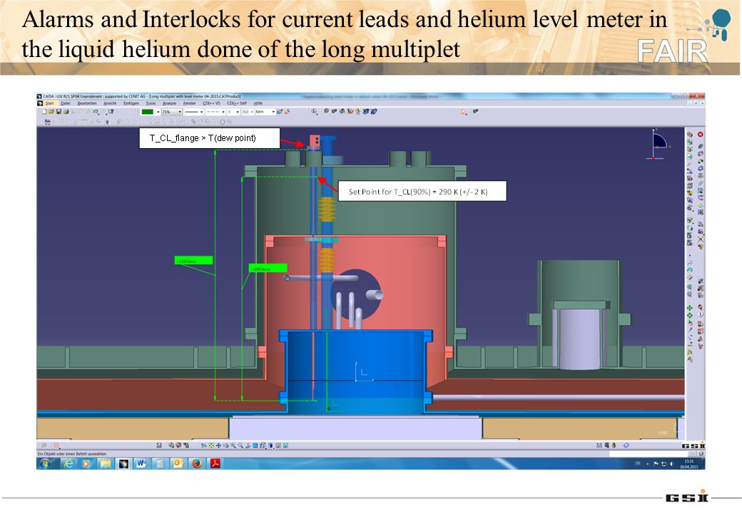
Alarms and Interlocks for current leads and helium level meter in the liquid helium dome of the long multiplet

15
Individual Operation Modes and their Logic Relations PredecessorSuccessor Normal Operation; Powering Permission (Slow-Discharge). Normal Operation; Powering Permission (Cryo-OK). 10. Current Leads Ready for Powering The temperature for the current leads at 90 % height towards the warm terminal end is regulated at the set point, e.g., 290 K +/- 2.0 K, and The temperature for the warm terminal flanges is above the dew point (10 ~ 40 °C), either maintained by the flange heaters or by the helium flow control.
. 10. Current Leads Ready for Powering The temperature for the current leads at 90 % height towards the warm terminal end is regulated at the set point, e.g., 290 K +/- 2.0 K, and The temperature for the warm terminal flanges is above the dew point (10 ~ 40 °C), either maintained by the flange heaters or by the helium flow control..")
16
Individual Operation Modes and their Logic Relations PredecessorSuccessor Current Leads Ready for Powering (Cryo- OK). Vacuum OK;...... Fast Discharge; Powering Permission (Slow-Discharge). 11. Powering Permission The interlock for Power Permission is authorized via a manual intervention by the cryogenic operator, based on:
. 11. Powering Permission The interlock for Power Permission is authorized via a manual intervention by the cryogenic operator, based on:.")
17
Individual Operation Modes and their Logic Relations 11. Powering Permission Vacuum OK: Insulation Vacuum in Magnet Cryostat 10 -3 mbar Alarm H 10 -1 mbar Hardwired Stop Interlock to close valves in feedbox (Isolation Mode) 100 mbar Hardwired Stop Interlock to close valves in distribution box to limit helium loses
 100 mbar Hardwired Stop Interlock to close valves in distribution box to limit helium loses.")
18
Individual Operation Modes and their Logic Relations 12. Quench Isolation mode All the cryogenic valves in the valve box are closed in order to limit the influence of the magnet quench on the individual test benches. This mode is also suitable for a catastrophic situation, e.g., the sudden loss of insulation vacuum in cryostat to air or to cold helium due to a breaking of process pipes. PredecessorSuccessor Powering Permission (Fast-Discharge). Quench recovery.
. Quench recovery..")
19
Individual Operation Modes and their Logic Relations 13. Quench Recovery Pressure in the helium vessel of the cryostat after quench may finally reach more than 2.2 bars. The vessel needs to be refilled with liquid helium via the LHe Filling mode. Once the temperature of the cold mass (dipole cryostat?) reaches more than 30 K, the cooldown mode from 80 K to 5 K may be necessary before the liquid helium is refilled. PredecessorSuccessor Quench Isolation mode. LHe Filling; Cool-Down 80 K – 5 K
 reaches more than 30 K, the cooldown mode from 80 K to 5 K may be necessary before the liquid helium is refilled. PredecessorSuccessor Quench Isolation mode. LHe Filling; Cool-Down 80 K – 5 K.")
20
Individual Operation Modes and their Logic Relations 6. Cold Stand-by Intermediate state when the shield cooling for one partly or fully LHe-filled cryostat is active only. If liquid helium is still left in the cryostat when the cold stand-by mode is terminated, the cryostat can be refilled via the LHe filling mode. Otherwise it goes automatically to the LHe emptying phase. PredecessorSuccessor Normal Operation. LHe Filling; LHe Emptying.

21
Individual Operation Modes and their Logic Relations 7. LHe emptying Liquid helium in the magnet cryostats is evaporated either by the heaters (the multiplets) or by static heat in-leak (the dipoles). It is ended when the liquid helium level is below 5 % of the total static head in the cryostat or the temperature of the cold mass is larger than 5 K.. PredecessorSuccessor LHe Filling; Cold Stand-by. Cool-Down 80 K – 5 K; Cold Floating 80 K – 100 K; Warm-Up 5 K – 300 K.
 or by static heat in-leak (the dipoles). It is ended when the liquid helium level is below 5 % of the total static head in the cryostat or the temperature of the cold mass is larger than 5 K.. PredecessorSuccessor LHe Filling; Cold Stand-by. Cool-Down 80 K – 5 K; Cold Floating 80 K – 100 K; Warm-Up 5 K – 300 K..")
22
Individual Operation Modes and their Logic Relations 8. Cold Floating 80 K – 100 K It permits that only the thermal shield is actively cooled at around 80 K; Such a mode may be necessary for the possible long intervene during the pre-series magnet testing on the test bench; This mode is active only when the magnet is free of liquid helium. PredecessorSuccessor LHe Emptying. Cool-Down 80 K – 5 K; Warm-Up 5 K – 300 K.

23
Individual Operation Modes and their Logic Relations 9. Warm-Up 5 K – 300 K After liquid helium is free in the cryostats, the gas helium at 80 K from the precooler is used for the warmup of the cold mass up to 30 K; Then the helium gas temperature is increased by keeping the Maximum ΔT (GHe - magnet) = 50 K; The electric heating power is necessary when the cold helium gas needs to be heated up to 300 K after it comes out of the magnet. For the long multiplet warm-up, about 15 kW is needed at maximum. PredecessorSuccessor Cool-Down 300 K – 80 K; Cool-Down 80 K – 5 K; Cold Floating 80 _ 300 K; LHe Emptying. Magnet Ready for Cryo- Operation.
 = 50 K; The electric heating power is necessary when the cold helium gas needs to be heated up to 300 K after it comes out of the magnet. For the long multiplet warm-up, about 15 kW is needed at maximum. PredecessorSuccessor Cool-Down 300 K – 80 K; Cool-Down 80 K – 5 K; Cold Floating 80 _ 300 K; LHe Emptying. Magnet Ready for Cryo- Operation..")
24
Warm-Up time estimation for long multiplet and dipole cryostats

25
The preliminary definition of the operation modes has been done for the Super-FRS magnet testing at CERN. Summary Thank you very much!

Similar presentations
 Helium distribution system for Super-FRS dipoles and multiplets MT/FAIR – Cryogenics and Magnets Y. Xiang,>")

, GSI, Darmstadt Yu Xiang, Hans Mueller* * Primay Beam Magnet Technology.>")


 27/02/20131 EUCARD : ESAC Review – CEA Saclay.>")
 Coordination meeting 6 th May 2015 K. Brodzinski HiLumi-LHC-CC-Cryo-PPT-18_v1.>")