Download presentation
Presentation is loading. Please wait.

1
Circuits and Circuit ElementsSection 1 © Houghton Mifflin Harcourt Publishing Company Today’s special SAT QOTD HW check: vocab 20 Notes HW I due next! Tesla coil

2
Circuits and Circuit ElementsSection 1 © Houghton Mifflin Harcourt Publishing Company If you have knowledge, let others light their candles in it. Margaret Fuller Fact: Most people use over 16,000 gallons of water in their lifetime, or 2.5 quarts per day.

3
Circuits and Circuit ElementsSection 1 © Houghton Mifflin Harcourt Publishing Company Preview Section 1 Schematic Diagrams and CircuitsSchematic Diagrams and Circuits Section 2 Resistors in Series or in ParallelResistors in Series or in Parallel Section 3 Complex Resistor CombinationComplex Resistor Combination

4
Circuits and Circuit ElementsSection 1 © Houghton Mifflin Harcourt Publishing Company Circuits and Circuit Elements Pd.4:Compare how current, voltage, and resistance are measured in a series and in a parallel electric circuit and identify the appropriate units of measurement. Pd.5:Analyze the relationships among voltage, resistance, and current in a complex circuit by using Ohm’s law to calculate voltage, resistance, and current at each resistor, any branch, and the overall circuit. Pd.7:Carry out calculations for electric power and electric energy for circuits. Pd.8:Summarize the function of electrical safety Indicators (including fuses, surge protectors, and breakers).
..")
5
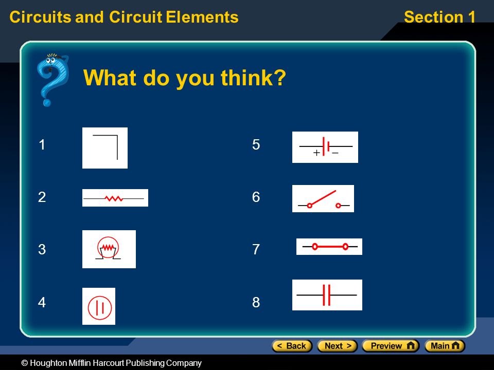
Circuits and Circuit ElementsSection 1 © Houghton Mifflin Harcourt Publishing Company What do you think? Scientists often use symbols to represent electrical components, such as batteries, bulbs, and wires. On the next slide, you will see the symbols for eight common electrical components that you have seen and discussed previously. Predict the component shown by looking at each symbol. Briefly explain why you think each symbol represents that particular electrical component.

6
Circuits and Circuit ElementsSection 1 © Houghton Mifflin Harcourt Publishing Company What do you think? 12341234 56785678
7
Circuits and Circuit ElementsSection 1 © Houghton Mifflin Harcourt Publishing Company Click below to watch the Visual Concept. Schematic Diagram and Common Symbols Visual Concept

8
Circuits and Circuit ElementsSection 1 © Houghton Mifflin Harcourt Publishing Company Schematic Diagrams Schematic diagrams use symbols to represent components. They show how the parts in an electrical device are arranged.

9
Circuits and Circuit ElementsSection 1 © Houghton Mifflin Harcourt Publishing Company Electric Circuits An electric circuit is a set of components providing a complete, closed-loop path for the movement of electrons. –Called a closed circuit If the path is broken, the electrons do not flow. –Called an open circuit

10
Circuits and Circuit ElementsSection 1 © Houghton Mifflin Harcourt Publishing Company Inside a Light bulb A complete conducting path is established inside the light bulb. –The tip of the bulb (a) is connected to one side of the filament (see the black line). –The threads on the side of the bulb (c) are connected to the other side of the filament (see the white line).
 is connected to one side of the filament (see the black line). –The threads on the side of the bulb (c) are connected to the other side of the filament (see the white line)..")
11
Circuits and Circuit ElementsSection 1 © Houghton Mifflin Harcourt Publishing Company Short Circuits A short circuit bypasses the light bulb or other load. –It is a closed circuit. –Electrons flow directly from - to + without passing through the bulb. –The current is large and the wire becomes hot. Short circuits in homes can cause fires. –Fuses or circuit breakers are designed to turn off the electron flow if short circuits occur.

12
Circuits and Circuit ElementsSection 1 © Houghton Mifflin Harcourt Publishing Company Potential Difference in Circuits A device that increases the PE of the electrons, such as a battery, is a source of emf (electromotive force). –Not really a force, but a PE difference Energy is conserved in electric circuits. –The potential difference ( V) for the battery equals the energy converted into heat as the electrons move through the bulb. Electrons gain energy (battery) and lose energy (bulb) as they make a complete trip.
 for the battery equals the energy converted into heat as the electrons move through the bulb. Electrons gain energy (battery) and lose energy (bulb) as they make a complete trip..")
13
Circuits and Circuit ElementsSection 1 © Houghton Mifflin Harcourt Publishing Company Click below to watch the Visual Concept. Visual Concept Internal Resistance, EMF, and Terminal Voltage

14
Circuits and Circuit ElementsSection 1 © Houghton Mifflin Harcourt Publishing Company Now what do you think? Draw schematic diagrams showing each of the following circuits: An open circuit including a battery, open switch, and bulb A closed circuit including a battery, closed switch, and resistor A short circuit including a battery, bulb, and closed switch

15
Circuits and Circuit ElementsSection 2 © Houghton Mifflin Harcourt Publishing Company What do you think? Figure (a) shows a single bulb and battery as seen before. Figures (b) and (c) each show two bulbs connected to the battery. The batteries and bulbs are all identical. Answer the three questions on the next slide and explain your reasoning.
 shows a single bulb and battery as seen before. Figures (b) and (c) each show two bulbs connected to the battery. The batteries and bulbs are all identical. Answer the three questions on the next slide and explain your reasoning..")
16
Circuits and Circuit ElementsSection 2 © Houghton Mifflin Harcourt Publishing Company What do you think? How will the brightness of (b) and (c) compare to each other and how does each compare to (a)? Explain. How will the brightness of (d) and (e) compare to each other and how does each compare to (a)? Explain. Compare the total current leaving the battery in each of the three circuits. Explain.
 and (c) compare to each other and how does each compare to (a). Explain. How will the brightness of (d) and (e) compare to each other and how does each compare to (a). Explain. Compare the total current leaving the battery in each of the three circuits. Explain..")
17
Circuits and Circuit ElementsSection 2 © Houghton Mifflin Harcourt Publishing Company Resistors in Series Series describes components of a circuit that provide a single path for the current. –The same electrons must pass through both light bulbs so the current in each is the same.

18
Circuits and Circuit ElementsSection 2 © Houghton Mifflin Harcourt Publishing Company Resistors in Series V battery = V 1 + V 2 –Conservation of energy V battery = IR 1 + IR 2 –Ohm’s law V battery = I(R 1 + R 2 ) V battery = IR equivalent R equivalent = R 1 + R 2
 V battery = IR equivalent R equivalent = R 1 + R 2")
19
Circuits and Circuit ElementsSection 2 © Houghton Mifflin Harcourt Publishing Company Equivalent Resistance Solving problems with series resistors: –Find the equivalent resistance. –Use R eq with Ohm’s law to find V or I. –Use I and R 1, R 2, etc. to find V 1, V 2, etc.

20
Circuits and Circuit ElementsSection 2 © Houghton Mifflin Harcourt Publishing Company Classroom Practice Problems A 6.00 V lantern battery is connected to each of the following bulb combinations. Find the current in each circuit and the potential difference across each bulb. –One bulb with a resistance of 7.50 –Two bulbs in series, each with a resistance of 7.50 –Four bulbs in series, each with a resistance of 7.50 Answers: –0.800 A, 6.00 V –0.400 A, 3.00 V each –0.200 A, 1.50 V each

21
Circuits and Circuit ElementsSection 2 © Houghton Mifflin Harcourt Publishing Company Resistors in Parallel Parallel describes components providing separate conducting paths with common connecting points. –The potential difference is the same for parallel components. –Electrons lose the same amount of energy with either path.

22
Circuits and Circuit ElementsSection 2 © Houghton Mifflin Harcourt Publishing Company Resistors in Parallel I battery = I 1 + I 2 –Conservation of charge –Ohm’s law V battery = V 1 = V 2 –Potential energy loss is the same across all parallel resistors. Because V battery = V 1 = V 2, the equation above reduces as follows:

23
Circuits and Circuit ElementsSection 2 © Houghton Mifflin Harcourt Publishing Company Equivalent Resistance Solving problems with parallel resistors: –Find the equivalent resistance. –Use R eq with Ohm’s law to find V or I total. –Use V to find I 1, I 2, etc.

24
Circuits and Circuit ElementsSection 2 © Houghton Mifflin Harcourt Publishing Company Classroom Practice Problems Find the equivalent resistance, the total current drawn by the circuit, and the current in each resistor for a 9.00 V battery connected to: –One 30.0 resistor –Three 30.0 resistors connected in parallel Answers: –30.0 , 0.300 A, 0.300 A –10.0 , 0.900 A, 0.300 A

25
Circuits and Circuit ElementsSection 2 © Houghton Mifflin Harcourt Publishing Company Answer

26
Circuits and Circuit ElementsSection 2 © Houghton Mifflin Harcourt Publishing Company Click below to watch the Visual Concept. Visual Concept Comparing Resistors in Series and in Parallel

27
Circuits and Circuit ElementsSection 2 © Houghton Mifflin Harcourt Publishing Company Summary

28
Circuits and Circuit ElementsSection 2 © Houghton Mifflin Harcourt Publishing Company Wiring Lights The series circuit shows a bulb burned out. –What will happen to the other bulbs? –Would this also happen in the parallel circuit? Assuming the bulbs are identical: –Which circuit will draw more current? –In which circuit are the bulbs brighter?

29
Circuits and Circuit ElementsSection 2 © Houghton Mifflin Harcourt Publishing Company Now what do you think? How will the brightness of (b) and (c) compare to each other and how does each compare to (a)? Explain. How will the brightness of (d) and (e) compare to each other and how does each compare to (a)? Explain. Compare the total current leaving the battery in each of the three circuits. Explain.
 and (c) compare to each other and how does each compare to (a). Explain. How will the brightness of (d) and (e) compare to each other and how does each compare to (a). Explain. Compare the total current leaving the battery in each of the three circuits. Explain..")
30
Circuits and Circuit ElementsSection 2 © Houghton Mifflin Harcourt Publishing Company Today’s special HW check; Q & A SAT QOTD Lab: Circuits Lab due next time

31
Circuits and Circuit ElementsSection 2 © Houghton Mifflin Harcourt Publishing Company Today’s special Turn in labs on front table SAT Science news-Molecular mechanisms Notes II HW II due next

32
Circuits and Circuit ElementsSection 3 © Houghton Mifflin Harcourt Publishing Company What do you think? Household circuits typically have many outlets and permanent fixtures such as hanging light fixtures on each circuit. Are these wired in series or in parallel? Why do you believe one of these methods has an advantage over the other method? What disadvantages would the other method of wiring have for household circuits?

33
Circuits and Circuit ElementsSection 3 © Houghton Mifflin Harcourt Publishing Company Click below to watch the Visual Concept. Visual Concept Analysis of Complex Circuits

34
Circuits and Circuit ElementsSection 3 © Houghton Mifflin Harcourt Publishing Company Complex Resistor Calculations R eq for 6.0 and 2.0 –Answer: 8.0 R eq for 8.0 and 4.0 –Answer: 2.7 R eq for 3.0 and 6.0 and 2.7 and 1.0 –Answer: 12.7 So, the resistance of all 6 resistors is equivalent to a single 12.7 resistor. To find the equivalent resistance for the circuit shown above, follow the steps shown to the right:

35
Circuits and Circuit ElementsSection 3 © Houghton Mifflin Harcourt Publishing Company Find the total current in the equivalent circuit. –Answer: 0.71 A –This is the current through the 1.0 , 6.0 (on the left), and 3.0 loads Find the total potential drop across the parallel combination of three resistors. –Answer: 1.9 V –Continued on the next slide For the 2.0 resistor, find the current and the potential difference. –To solve this problem, use the step-by-step approach shown. Complex Resistor Calculations
, and 3.0 loads Find the total potential drop across the parallel combination of three resistors. –Answer: 1.9 V –Continued on the next slide For the 2.0 resistor, find the current and the potential difference. –To solve this problem, use the step-by-step approach shown. Complex Resistor Calculations.")
36
Circuits and Circuit ElementsSection 3 © Houghton Mifflin Harcourt Publishing Company Find the current through the combined 6.0 and 2.0 resistor. –Answer: 0.24 A Find the potential difference across the 2.0 resistor. –Answer: 0.48 V Complex Resistor Calculations

37
Circuits and Circuit ElementsSection 3 © Houghton Mifflin Harcourt Publishing Company For the circuit shown, find the: –Equivalent resistance –Current through the 3.0 resistor –Potential difference across the 6.0 resistor Answers: –6.6 , 1.8 A, 6.5 V Classroom Practice Problems

38
Circuits and Circuit ElementsSection 3 © Houghton Mifflin Harcourt Publishing Company Now what do you think? Household circuits typically have many outlets and permanent fixtures such as hanging light fixtures on each circuit. Are these wired in series or in parallel? Why do you believe one of these methods has an advantage over the other method? What disadvantages would the other method of wiring have for household circuits?

39
Circuits and Circuit ElementsSection 3 © Houghton Mifflin Harcourt Publishing Company Today’s special HW check; Q & A Quiz! Secret lives of scientists – Jim Gates Review for test SAT QOTD Test next time!

40
Circuits and Circuit ElementsSection 3 © Houghton Mifflin Harcourt Publishing Company Today’s special Test 18 Circuits Enter MC answers into Smart response; Show all work on paper test and turn it in on front desk when finished Vocab 19 Magnetism due next time

Similar presentations


 Electric Current.>")


>")