Download presentation
Presentation is loading. Please wait.

2
Triaxial State of Stress at any Critical Point in a Loaded Body
Cartesian stress components are found first in selected x-y-z coordinate axes (Fig. 4.1) Three mutually perpendicular principal planes are found at unique orientations: NO Shear stresses on these planes Principal Normal Stresses: 1, 3, 2, one of which is maximum normal stress at the point Three mutually perpendicular Principal Shearing Planes (Planes of max. shear) Principal Shearing Stresses: 1, 2, 3, one of which is the maximum shear stress at the point Normal stresses are NOT zero, NOT principal stresses and depend on the type of loading
 Three mutually perpendicular principal planes are found at unique orientations: NO Shear stresses on these planes. Principal Normal Stresses: 1, 3, 2, one of which is maximum normal stress at the point. Three mutually perpendicular Principal Shearing Planes (Planes of max. shear) Principal Shearing Stresses: 1, 2, 3, one of which is the maximum shear stress at the point. Normal stresses are NOT zero, NOT principal stresses and depend on the type of loading.")
3
3-D Stress Transformations Equations
Relate Known Cartesian Stress Components at Any Point with Unknown Stress Components on Any Other Plane through the SAME Point From equilibrium conditions of infinitesimal pyramid Important for the Unique Orientations of the Principal Normal and Shearing Planes Stress Cubic Equation- three real roots are the Principal Normal Stresses, 1, 2, 3. Principal Shearing Stresses can be calculated from the Principal Normal Stresses as follows:

4
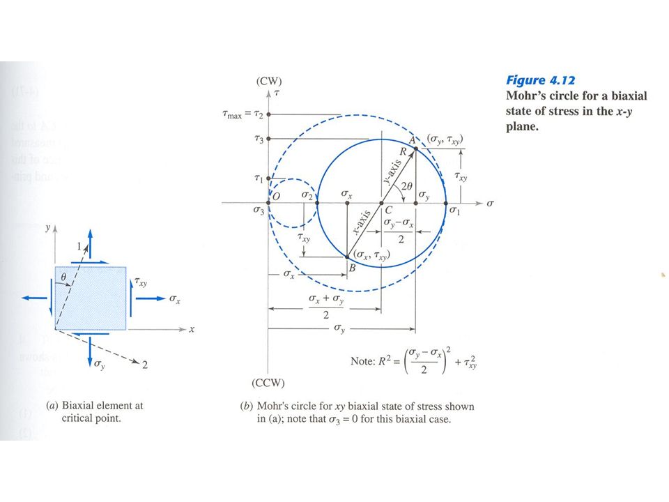
Mohr’s Circle Analogy for Stress – Graphical Transformation of 2-D Stress State
Principal stress solution of stress cube eq. for stresses in the x-y plane (Fig. 4.12) Analogy with the equation of a circle plotted in the - plane leads to Mohr’s circle for biaxial stress: Sign convention for plotting the Mohr’s circle (normal stress is positive for tension, shear is positive for clockwise (CW) couple) Two additional Mohr’s circle for triaxial stress states Find orientation of principal axes from the Mohr’s circle
 Analogy with the equation of a circle plotted in the - plane leads to Mohr’s circle for biaxial stress: Sign convention for plotting the Mohr’s circle (normal stress is positive for tension, shear is positive for clockwise (CW) couple) Two additional Mohr’s circle for triaxial stress states. Find orientation of principal axes from the Mohr’s circle.")
6
Strain Cubic Equation and Principal Strains
STRAIN – a measure of loading severity, defining the intensity and direction of deformation at a point, w.r.t. specified planes through that point. Strain state at a point is completely defined by: Three normal and three shearing strain components in the selected x-y-z coordinate system, OR Three PRINCIPAL strains and their directions from Strain Cubic Equation (similar to Stress Cubic Equation, where ’s are replaced by ’s, and shear stresses, ’s, are replaced by one-half of ’s.)
")
7
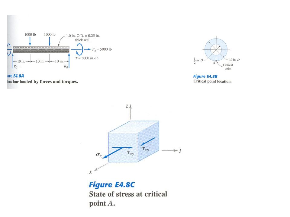
Summary of Example Problems
Example 4.8 – Principal Stresses in Beam Hollow cylindrical member subjected to transverse forces (four-point bending), axial force and torque Sketch state of stress at critical point (bottom edge) Use “stress cubic equation” to find principal stresses from calculated Cartesian stresses at critical point Find principal shear stresses from principal normal ones Example 4.9 –Mohr’s Circle for Stress Semi-graphical analysis of biaxial stress state at critical point of previous example cube is replaced by 2-D sketch in x-y plane Principal normal and shear stresses are found graphically from the basic and the two additional Mohr circles, respectively
, axial force and torque. Sketch state of stress at critical point (bottom edge) Use stress cubic equation to find principal stresses from calculated Cartesian stresses at critical point. Find principal shear stresses from principal normal ones. Example 4.9 –Mohr’s Circle for Stress. Semi-graphical analysis of biaxial stress state at critical point of previous example cube is replaced by 2-D sketch in x-y plane. Principal normal and shear stresses are found graphically from the basic and the two additional Mohr circles, respectively.")
11
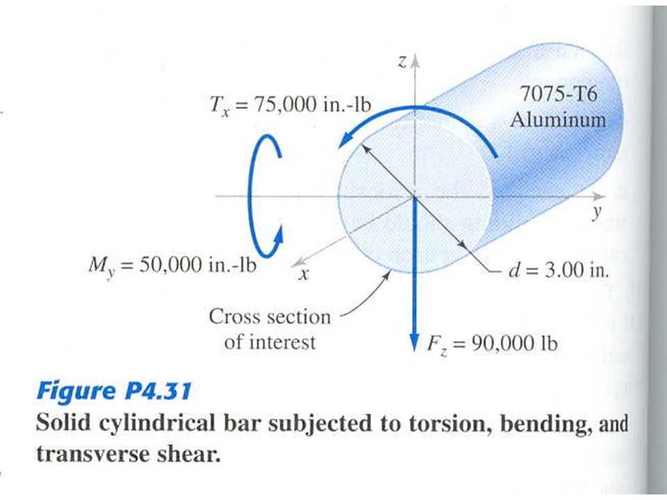
Summary of Textbook Problems – Problem 4.31, Principal Stresses
Identify critical points for each of the three types of loading applied on the bar Locations where stresses are amplified by superposition of effects from different loads – top end of vertical diameter and left end of horizontal one Sketch infinitesimal cube elements for the states of stress at critical points Calculate stresses at critical points, in the given system of Cartesian coordinates Use “stress cubic equation” to find the principal stresses at each of the two critical points Top edge: 1=26,047 psi, 2=0, 3=-7683 psi Left edge: 1=31,124 psi, 2=0, 3=-31,124 psi Calculate the maximum shearing stress at each point Top edge: max= 16,865 psi, while at the left edge: max= 31,124 psi

Similar presentations


 Spring 2008>")


 The load, the shock,>")


>")

 Spring 2008 Dr. Konstantinos A. Sierros.>")
 Is there any general method to determine stresses on any arbitrary.>")


