Download presentation
Presentation is loading. Please wait.

1
Chapter 5 MASS AND ENERGY ANALYSIS OF CONTROL VOLUMES
Thermodynamics: An Engineering Approach Yunus A. Cengel, Michael A. Boles McGraw-Hill© Chapter 5 MASS AND ENERGY ANALYSIS OF CONTROL VOLUMES Dr. Kagan ERYURUK Copyright © The McGraw-Hill Companies, Inc. Permission required for reproduction or display.

2
CONSERVATION OF MASS Conservation of mass: Mass, like energy, is a conserved property, and it cannot be created or destroyed during a process. Closed systems: The mass of the system remain constant during a process. Control volumes: Mass can cross the boundaries, and so we must keep track of the amount of mass entering and leaving the control volume. Mass is conserved even during chemical reactions. Mass m and energy E can be converted to each other according to where c is the speed of light in a vacuum, which is c = 108 m/s. The mass change due to energy change is absolutely negligible.

3
Mass and Volume Flow Rates
Definition of average velocity Volume flow rate Mass flow rate The average velocity Vavg is defined as the average speed through a cross section. The volume flow rate is the volume of fluid flowing through a cross section per unit time.

4
Conservation of Mass Principle
The conservation of mass principle for a control volume: The net mass transfer to or from a control volume during a time interval t is equal to the net change (increase or decrease) in the total mass within the control volume during t. Conservation of mass principle for an ordinary bathtub.
 in the total mass within the control volume during t. Conservation of mass principle for an ordinary bathtub.")
5
Mass Balance for Steady-Flow Processes
During a steady-flow process, the total amount of mass contained within a control volume does not change with time (mCV = constant). Then the conservation of mass principle requires that the total amount of mass entering a control volume equal the total amount of mass leaving it. For steady-flow processes, we are interested in the amount of mass flowing per unit time, that is, the mass flow rate. Multiple inlets and exits Many engineering devices such as nozzles, diffusers, turbines, compressors, and pumps involve a single stream (only one inlet and one outlet). Single stream Conservation of mass principle for a two-inlet–one-outlet steady-flow system.
. Then the conservation of mass principle requires that the total amount of mass entering a control volume equal the total amount of mass leaving it. For steady-flow processes, we are interested in the amount of mass flowing per unit time, that is, the mass flow rate. Multiple inlets and exits. Many engineering devices such as nozzles, diffusers, turbines, compressors, and pumps involve a single stream (only one inlet and one outlet). Single stream. Conservation of mass principle for a two-inlet–one-outlet steady-flow system.")
6
Special Case: Incompressible Flow
The conservation of mass relations can be simplified even further when the fluid is incompressible, which is usually the case for liquids. Steady, incompressible Steady, incompressible flow (single stream) There is no such thing as a “conservation of volume” principle. However, for steady flow of liquids, the volume flow rates, as well as the mass flow rates, remain constant since liquids are essentially incompressible substances. During a steady-flow process, volume flow rates are not necessarily conserved although mass flow rates are.
 There is no such thing as a conservation of volume principle. However, for steady flow of liquids, the volume flow rates, as well as the mass flow rates, remain constant since liquids are essentially incompressible substances. During a steady-flow process, volume flow rates are not necessarily conserved although mass flow rates are.")
7
A garden hose attached with a nozzle is used to fill a 10-gal bucket
A garden hose attached with a nozzle is used to fill a 10-gal bucket. The inner diameter of the hose is 2 cm, and it reduces to 0.8 cm at the nozzle exit (figure). If it takes 50 s to fill the bucket with water, determine (a) the volume and mass flow rates of water through the hose, and (b) the average velocity of water at the nozzle exit.
. If it takes 50 s to fill the bucket with water, determine (a) the volume and mass flow rates of water through the hose, and (b) the average velocity of water at the nozzle exit.")
8
FLOW WORK AND THE ENERGY OF A FLOWING FLUID
Flow work, or flow energy: The work (or energy) required to push the mass into or out of the control volume. This work is necessary for maintaining a continuous flow through a control volume. In the absence of acceleration, the force applied on a fluid by a piston is equal to the force applied on the piston by the fluid. Schematic for flow work.
 required to push the mass into or out of the control volume. This work is necessary for maintaining a continuous flow through a control volume. In the absence of acceleration, the force applied on a fluid by a piston is equal to the force applied on the piston by the fluid. Schematic for flow work.")
9
Total Energy of a Flowing Fluid
The flow energy is automatically taken care of by enthalpy. In fact, this is the main reason for defining the property enthalpy. h = u + Pv The total energy consists of three parts for a nonflowing fluid and four parts for a flowing fluid.

10
Energy Transport by Mass
When the kinetic and potential energies of a fluid stream are negligible The product is the energy transported into control volume by mass per unit time.

11
Example: Steam is leaving a 4-L pressure cooker whose operating pressure is 150 kPa (figure). It is observed that the amount of liquid in the cooker has decreased by 0.6 L in 40 min after the steady operating conditions are established, and the cross-sectional area of the exit opening is 8 mm2. Determine (a) the mass flow rate of the steam and the exit velocity, (b) the total and flow energies of the steam per unit mass, and (c) the rate at which energy leaves the cooker by steam. Saturation conditions exist in a pressure cooker at all times after the steady operating conditions are established. Therefore, the liquid has the properties of saturated liquid and the exiting steam has the properties of saturated vapor at the operating pressure.

12
h=u+Pv and that the kinetic and potential energies are disregarded, the flow and total energies of the exiting steam are;

13
ENERGY ANALYSIS OF STEADY-FLOW SYSTEMS
Under steady-flow conditions, the mass and energy contents of a control volume remain constant. Many engineering systems such as power plants operate under steady conditions. Under steady-flow conditions, the fluid properties at an inlet or exit remain constant (do not change with time).
.")
14
Mass and Energy balances for a steady-flow process
Mass balance Energy balance A water heater in steady operation.

15
SOME STEADY-FLOW ENGINEERING DEVICES
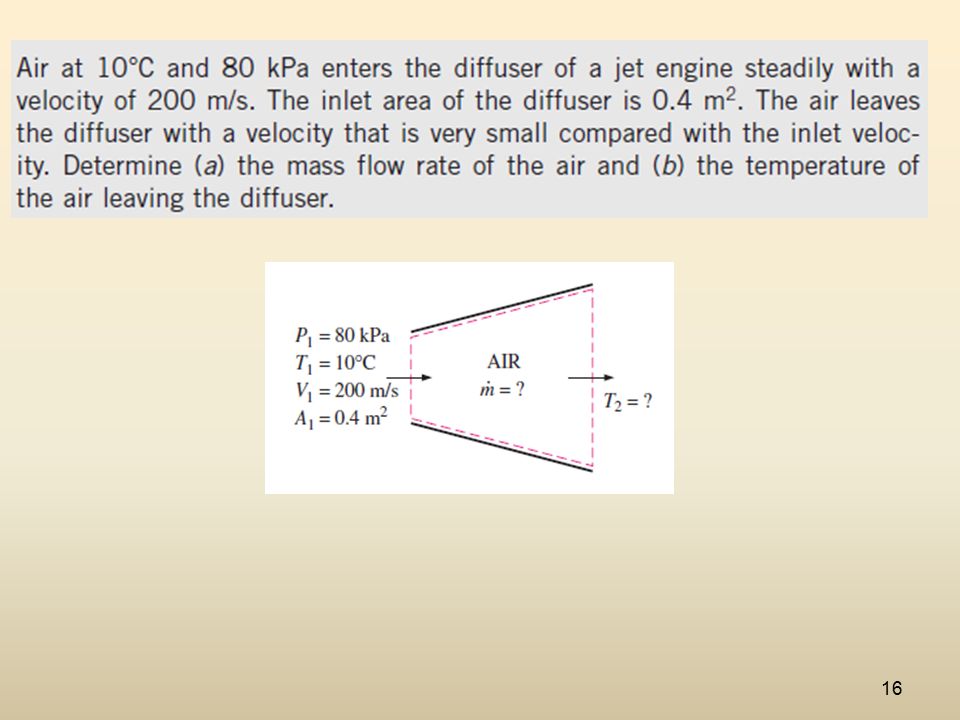
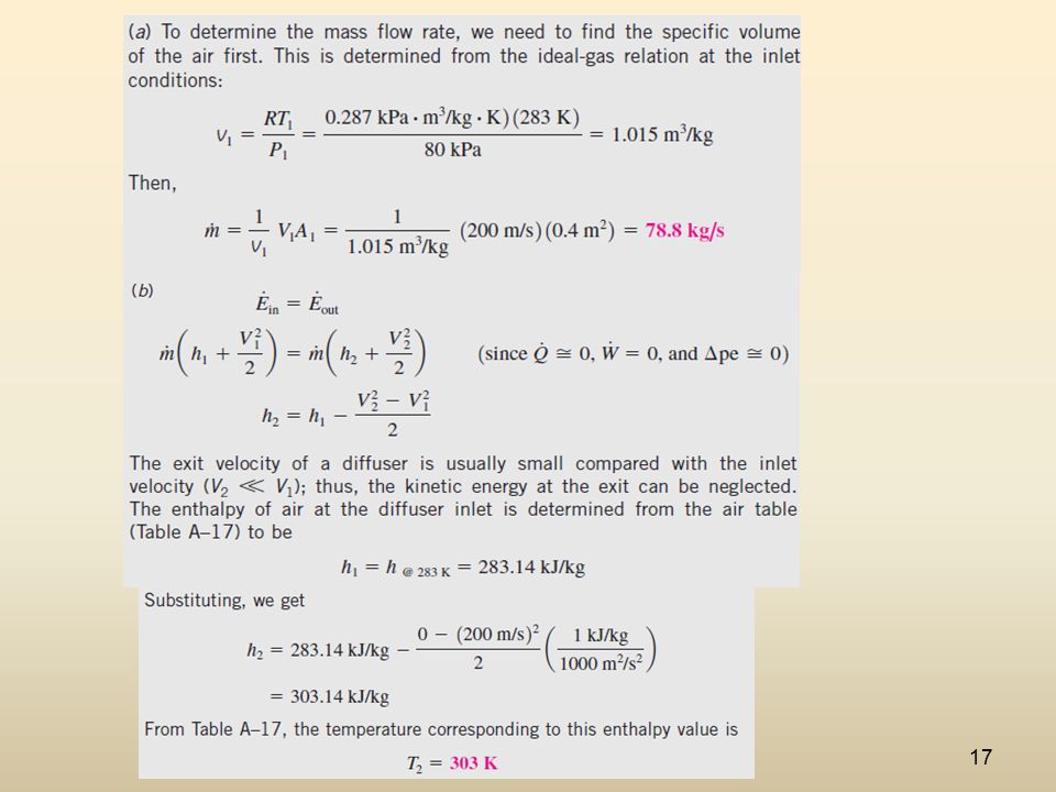
Jet engines, rockets, spacecraft, and even garden hoses. A nozzle is a device that increases the velocity of a fluid at the expense of pressure. A diffuser is a device that increases the pressure of a fluid by slowing it down. The cross-sectional area of a nozzle decreases in the flow direction for subsonic flows and increases for supersonic flows. The reverse is true for diffusers. Nozzles and Diffusers Energy balance for a nozzle or diffuser: Nozzles and diffusers are shaped so that they cause large changes in fluid velocities and thus kinetic energies.

18
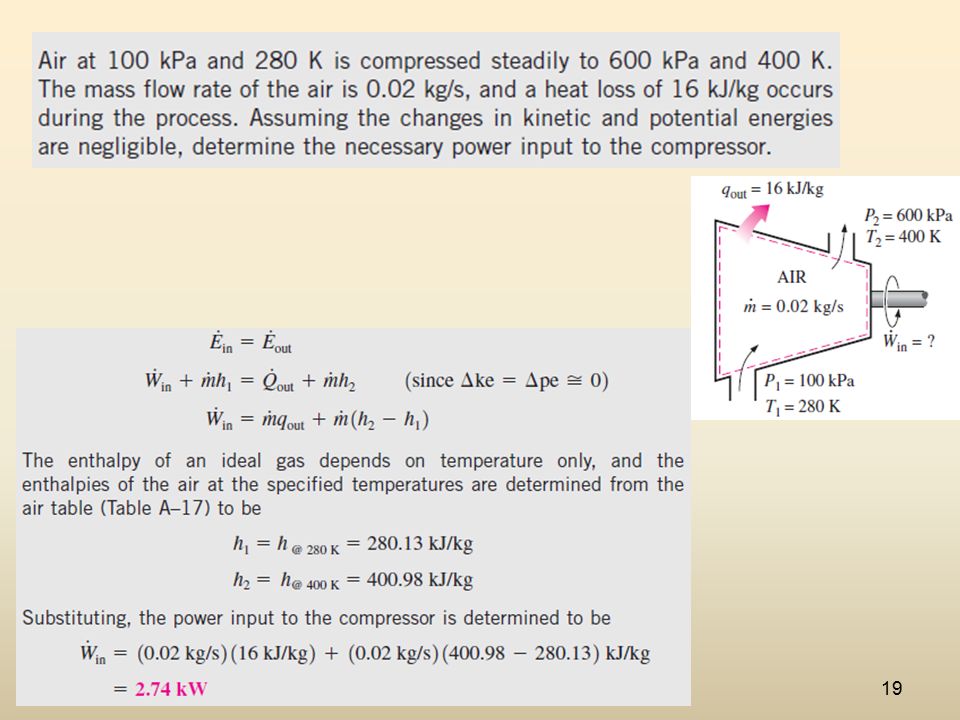
Turbines and Compressors
Turbine drives the electric generator In steam, gas, or hydroelectric power plants. Compressors, as well as pumps and fans, are devices used to increase the pressure of a fluid. Work is supplied to these devices from an external source through a rotating shaft. Energy balance for the compressor in this figure:

20
Mixing chambers In engineering applications, the section where the mixing process takes place is commonly referred to as a mixing chamber. Energy balance for the adiabatic mixing chamber in the figure is: The T-elbow of an ordinary shower serves as the mixing chamber for the hot- and the cold-water streams.

21
Consider an ordinary shower where hot water at 60 °C is mixed with cold water at 10 °C. If it is desired that a steady stream of warm water at 43 °C be supplied, determine the ratio of the mass flow rates of the hot to cold water. Assume the heat losses from the mixing chamber to be negligible and the mixing to take place at a pressure of 140 kPa. 10C 60C 43C 140 kPa

22
The saturation temperature of water at 140 kPa is 108. 85 °F
The saturation temperature of water at 140 kPa is °F. Since the temperatures of all three streams are below this value (T <Tsat), the water in all three streams exists as a compressed liquid . A compressed liquid can be approximated as a saturated liquid at the given temperature. Thus, h1= hf at 60 °C= kJ/kg 1.94 h2= hf at 10 °C= kJ/kg h3= hf at 43 °C= kJ/kg
, the water in all three streams exists as a compressed liquid . A compressed liquid can be approximated as a saturated liquid at the given temperature. Thus, h1= hf at 60 °C= kJ/kg h2= hf at 10 °C= kJ/kg. h3= hf at 43 °C= kJ/kg.")
23
Heat exchangers Heat exchangers are devices where two moving fluid streams exchange heat without mixing. Heat exchangers are widely used in various industries, and they come in various designs. The heat transfer associated with a heat exchanger may be zero or nonzero depending on how the control volume is selected. Mass and energy balances for the adiabatic heat exchanger in the figure is: A heat exchanger can be as simple as two concentric pipes.

24
Pipe and duct fow The transport of liquids or gases in pipes and ducts is of great importance in many engineering applications. Flow through a pipe or a duct usually satisfies the steady-flow conditions. Pipe or duct flow may involve more than one form of work at the same time. Energy balance for the pipe flow shown in the figure is Heat losses from a hot fluid flowing through an uninsulated pipe or duct to the cooler environment may be very significant.

25
ENERGY ANALYSIS OF UNSTEADY-FLOW PROCESSES
Many processes of interest, however, involve changes within the control volume with time. Such processes are called unsteady-flow, or transient-flow, processes. Charging of a rigid tank from a supply line is an unsteady-flow process since it involves changes within the control volume. The shape and size of a control volume may change during an unsteady-flow process.

Similar presentations


>")


.>")


>")


