Download presentation
Presentation is loading. Please wait.

1
Java How to Program, 9/e ©1992-2012 by Pearson Education, Inc. All Rights Reserved.

4
In Chapters 12–13, you design and implement an object-oriented automated teller machine (ATM) software system. Concise, carefully paced, complete design and implementation experience. Perform the steps of an object-oriented design (OOD) process using the UML Sections 12.2––12.7 and 13.2–13.3 Relate these steps to the object-oriented concepts discussed in Chapters 2–10 Work with six popular types of UML diagrams Chapter 13—tune the design with inheritance, then fully implement the ATM. An end-to-end learning experience that concludes with a detailed walkthrough of the complete Java code. ©1992-2012 by Pearson Education, Inc. All Rights Reserved.
 process using the UML Sections 12.2––12.7 and 13.2–13.3 Relate these steps to the object-oriented concepts discussed in Chapters 2–10 Work with six popular types of UML diagrams Chapter 13—tune the design with inheritance, then fully implement the ATM. An end-to-end learning experience that concludes with a detailed walkthrough of the complete Java code. © by Pearson Education, Inc. All Rights Reserved..")
5
A requirements document specifies the purpose of the ATM system and what it must do. Requirements Document A local bank intends to install a new automated teller machine (ATM) to allow users (i.e., bank customers) to perform basic financial transactions Each user can have only one account at the bank. ATM users view their account balance withdraw cash deposit funds ©1992-2012 by Pearson Education, Inc. All Rights Reserved.
 to allow users (i.e., bank customers) to perform basic financial transactions Each user can have only one account at the bank. ATM users view their account balance withdraw cash deposit funds © by Pearson Education, Inc. All Rights Reserved..")
6
ATM user interface: a screen that displays messages to the user a keypad that receives numeric input from the user a cash dispenser that dispenses cash to the user and a deposit slot that receives deposit envelopes from the user. The cash dispenser begins each day loaded with 500 $20 bills. ©1992-2012 by Pearson Education, Inc. All Rights Reserved.

8
Develop software to perform the financial transactions initiated by bank customers through the ATM. The bank will integrate the software with the ATM’s hardware at a later time. Software should encapsulate the functionality of the hardware devices within software components, but it need not concern itself with how these devices perform their duties. Use the computer’s monitor to simulate the ATM’s screen, and the computer’s keyboard to simulate the ATM’s keypad. ©1992-2012 by Pearson Education, Inc. All Rights Reserved.

9
An ATM session consists of authenticating a user based on an account number and personal identification number (PIN) creating and executing financial transactions To authenticate a user and perform transactions interact with the bank’s account information database For each account, the database stores an account number, a PIN and a balance indicating the amount of money in the account. ©1992-2012 by Pearson Education, Inc. All Rights Reserved.

10
Simplifying Assumptions: the bank plans to build only one ATM, so we need not worry about multiple ATMs accessing this database at the same time the bank does not make any changes to the information in the database while a user is accessing the ATM. an ATM faces reasonably complicated security issues that are beyond the scope of a first or second programming course. the bank trusts the ATM to access and manipulate the information in the database without significant security measures. ©1992-2012 by Pearson Education, Inc. All Rights Reserved.

11
Upon first approaching the ATM, the user should experience the following sequence of events (shown in Fig. 12.1): The screen displays Welcome! and prompts the user to enter an account number. The user enters a five-digit account number using the keypad. The screen prompts the user to enter the PIN (personal identification number) associated with the specified account number. The user enters a five-digit PIN using the keypad. If the user enters a valid account number and the correct PIN for that account, the screen displays the main menu (Fig. 12.2). If the user enters an invalid account number or an incorrect PIN, the screen displays an appropriate message, then the ATM returns to Step 1 to restart the authentication process. ©1992-2012 by Pearson Education, Inc. All Rights Reserved.
: The screen displays Welcome. and prompts the user to enter an account number. The user enters a five-digit account number using the keypad. The screen prompts the user to enter the PIN (personal identification number) associated with the specified account number. The user enters a five-digit PIN using the keypad. If the user enters a valid account number and the correct PIN for that account, the screen displays the main menu (Fig. 12.2). If the user enters an invalid account number or an incorrect PIN, the screen displays an appropriate message, then the ATM returns to Step 1 to restart the authentication process. © by Pearson Education, Inc. All Rights Reserved..")
13
After the ATM authenticates the user, the main menu (Fig. 12.2) should contain a numbered option for each of the three types of transactions: balance inquiry (option 1), withdrawal (option 2) and deposit (option 3). It also should contain an option to allow the user to exit the system (option 4). The user then chooses either to perform a transaction (by entering 1, 2 or 3) or to exit the system (by entering 4). ©1992-2012 by Pearson Education, Inc. All Rights Reserved.
 should contain a numbered option for each of the three types of transactions: balance inquiry (option 1), withdrawal (option 2) and deposit (option 3). It also should contain an option to allow the user to exit the system (option 4). The user then chooses either to perform a transaction (by entering 1, 2 or 3) or to exit the system (by entering 4). © by Pearson Education, Inc. All Rights Reserved..")
14
If the user enters 1 to make a balance inquiry, the screen displays the user’s account balance. To do so, the ATM must retrieve the balance from the bank’s database. ©1992-2012 by Pearson Education, Inc. All Rights Reserved.

15
The following steps describe what occurs when the user enters 2 to make a withdrawal: The screen displays a menu of standard withdrawal amounts and an option to cancel the transaction. The user enters a menu selection using the keypad. If the withdrawal amount is greater than the user’s account balance, the screen displays a message stating this and telling the user to choose a smaller amount. The ATM then returns to Step 1. If the withdrawal amount chosen is less than or equal to the user’s account balance (i.e., an acceptable amount), the ATM proceeds to Step 4. If the user chooses to cancel, the ATM displays the main menu and waits for user input. ©1992-2012 by Pearson Education, Inc. All Rights Reserved.
, the ATM proceeds to Step 4. If the user chooses to cancel, the ATM displays the main menu and waits for user input. © by Pearson Education, Inc. All Rights Reserved..")
16
If the cash dispenser contains enough cash, the ATM proceeds to Step 5. Otherwise, the screen displays a message indicating the problem and telling the user to choose a smaller withdrawal amount. The ATM then returns to Step 1. The ATM debits the withdrawal amount from the user’s account in the bank’s database. The cash dispenser dispenses the desired amount of money to the user. The screen displays a message reminding the user to take the money. ©1992-2012 by Pearson Education, Inc. All Rights Reserved.

18
The following steps describe the actions that occur when the user enters 3 to make a deposit: The screen prompts the user to enter a deposit amount or type 0 (zero) to cancel. The user enters a deposit amount or 0 using the keypad. If the user specifies a deposit amount, the ATM proceeds to Step 4. If the user chooses to cancel the transaction (by entering 0), the ATM displays the main menu and waits for user input. The screen displays a message telling the user to insert a deposit envelope. If the deposit slot receives a deposit envelope within two minutes, the ATM credits the deposit amount to the user’s account in the bank’s database (i.e., adds the deposit amount to the user’s account balance). ©1992-2012 by Pearson Education, Inc. All Rights Reserved.
, the ATM displays the main menu and waits for user input. The screen displays a message telling the user to insert a deposit envelope. If the deposit slot receives a deposit envelope within two minutes, the ATM credits the deposit amount to the user’s account in the bank’s database (i.e., adds the deposit amount to the user’s account balance). © by Pearson Education, Inc. All Rights Reserved..")
19
After the system successfully executes a transaction, it should return to the main menu so that the user can perform additional transactions. If the user exits the system, the screen should display a thank you message, then display the welcome message for the next user. ©1992-2012 by Pearson Education, Inc. All Rights Reserved.

20
Analyzing the ATM System The preceding statement is a simplified example of a requirements document Typically the result of a detailed process of requirements gathering A systems analyst might interview banking experts to gain a better understanding of what the software must do would use the information gained to compile a list of system requirements to guide systems designers as they design the system. ©1992-2012 by Pearson Education, Inc. All Rights Reserved.

21
The software life cycle specifies the stages through which software goes from the time it’s first conceived to the time it’s retired from use. These stages typically include: analysis, design, implementation, testing and debugging, deployment, maintenance and retirement. Several software life-cycle models exist Waterfall models perform each stage once in succession Iterative models may repeat one or more stages several times throughout a product’s life cycle ©1992-2012 by Pearson Education, Inc. All Rights Reserved.

22
The analysis stage focuses on defining the problem to be solved. When designing any system, one must solve the problem right, but of equal importance, one must solve the right problem. Our requirements document describes the requirements of our ATM system in sufficient detail that you need not go through an extensive analysis stage—it’s been done for you. ©1992-2012 by Pearson Education, Inc. All Rights Reserved.

23
Use case modeling identifies the use cases of the system, each representing a different capability that the system provides to its clients. “View Account Balance” “Withdraw Cash” “Deposit Funds” Each use case describes a typical scenario for which the user uses the system. ©1992-2012 by Pearson Education, Inc. All Rights Reserved.

24
A use case diagram models the interactions between a system’s clients and its use cases. Shows the kinds of interactions users have with a system without providing the details Often accompanied by informal text that gives more detail—like the text that appears in the requirements document. Produced during the analysis stage of the software life cycle. Figure 12.4 shows the use case diagram for our ATM system. Stick figure represents an actor, which defines the roles that an external entity—such as a person or another system—plays when interacting with the system. ©1992-2012 by Pearson Education, Inc. All Rights Reserved.

26
During the analysis stage, systems designers focus on understanding the requirements document to produce a high-level specification that describes what the system is supposed to do. The output of the design stage—a design specification— should specify clearly how the system should be constructed to satisfy these requirements. In the next several sections, we perform the steps of a simple object-oriented design (OOD) process on the ATM system to produce a design specification containing a collection of UML diagrams and supporting text. We present our own simplified design process, designed for students in first and second programming courses. ©1992-2012 by Pearson Education, Inc. All Rights Reserved.
 process on the ATM system to produce a design specification containing a collection of UML diagrams and supporting text. We present our own simplified design process, designed for students in first and second programming courses. © by Pearson Education, Inc. All Rights Reserved..")
27
A system is a set of components that interact to solve a problem. System structure describes the system’s objects and their interrelationships. System behavior describes how the system changes as its objects interact with one another. Every system has both structure and behavior— designers must specify both. ©1992-2012 by Pearson Education, Inc. All Rights Reserved.

28
The UML 2 standard specifies 13 diagram types for documenting the system models. Each models a distinct characteristic of a system’s structure or behavior—six diagrams relate to system structure, the remaining seven to system behavior. We list only the six diagram types used in our case study. ©1992-2012 by Pearson Education, Inc. All Rights Reserved.

29
Use case diagrams model the interactions between a system and its external entities (actors) in terms of use cases. Class diagrams model the classes, or “building blocks,” used in a system. State machine diagrams model the ways in which an object changes state. An object’s state is indicated by the values of all its attributes at a given time. When an object changes state, it may behave differently in the system. Activity diagrams model an object’s activity—its workflow (sequence of events) during program execution. An activity diagram models the actions the object performs and specifies the order in which it performs them. ©1992-2012 by Pearson Education, Inc. All Rights Reserved.
 during program execution. An activity diagram models the actions the object performs and specifies the order in which it performs them. © by Pearson Education, Inc. All Rights Reserved..")
30
Communication diagrams (called collaboration diagrams in earlier versions of the UML) model the interactions among objects in a system, with an emphasis on what interactions occur. Sequence diagrams also model the interactions among the objects in a system, but emphasize when interactions occur. Within these above-listed six diagram types, only Class diagrams model system structure. The rest of them model system behavior. ©1992-2012 by Pearson Education, Inc. All Rights Reserved.

31
Identify the classes that are needed to build the system by analyzing the nouns and noun phrases that appear in the requirements document. We introduce UML class diagrams to model these classes. Important first step in defining the system’s structure. Review the requirements document and identify key nouns and noun phrases to help us identify classes that comprise the ATM system. We may decide that some of these nouns and noun phrases are actually attributes of other classes in the system. We may also conclude that some of the nouns do not correspond to parts of the system and thus should not be modeled at all. Additional classes may become apparent to us as we proceed through the design process. ©1992-2012 by Pearson Education, Inc. All Rights Reserved.

33
We create classes only for the nouns and noun phrases that have significance in the ATM system. Though the requirements document frequently describes a “transaction” in a general sense, we do not model the broad notion of a financial transaction at this time. Instead, we model the three types of transactions (i.e., “balance inquiry,” “withdrawal” and “deposit”) as individual classes. These classes possess specific attributes needed for executing the transactions they represent. ©1992-2012 by Pearson Education, Inc. All Rights Reserved.
 as individual classes. These classes possess specific attributes needed for executing the transactions they represent. © by Pearson Education, Inc. All Rights Reserved..")
34
Classes: ATM screen keypad cash dispenser deposit slot account bank database balance inquiry withdrawal deposit ©1992-2012 by Pearson Education, Inc. All Rights Reserved.

35
The UML enables us to model, via class diagrams, the classes in the ATM system and their interrelationships. Figure 12.6 represents class ATM. Each class is modeled as a rectangle with three compartments. The top one contains the name of the class centered horizontally in boldface. The middle compartment contains the class’s attributes. The bottom compartment contains the class’s operations. ©1992-2012 by Pearson Education, Inc. All Rights Reserved.

37
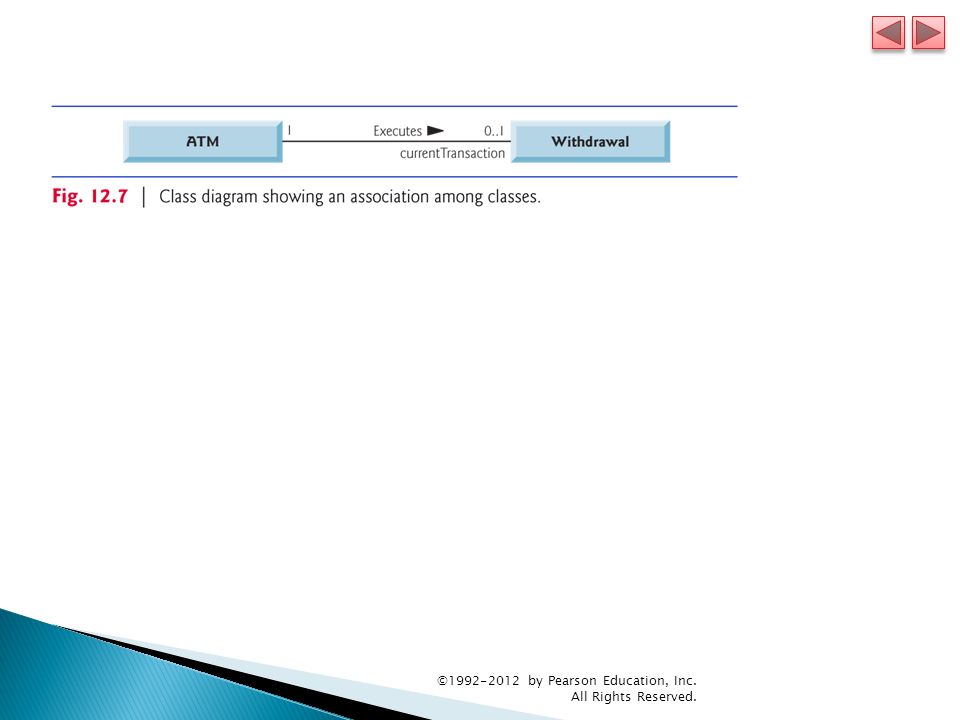
Class diagrams also show the relationships between the classes of the system. Figure 12.7 shows how our classes ATM and Withdrawal relate to one another. Notice that the rectangles representing classes in this diagram are not subdivided into compartments. The UML allows the suppression of class attributes and operations in this manner to create more readable diagrams, when appropriate. Such a diagram is said to be an elided diagram. ©1992-2012 by Pearson Education, Inc. All Rights Reserved.

39
The solid line that connects the two classes represents an association—a relationship between classes. The numbers near each end of the line are multiplicity values, which indicate how many objects of each class participate in the association. At any given moment, one ATM object participates in an association with either zero or one Withdrawal objects— zero if the current user is not currently performing a transaction or has requested a different type of transaction, and one if the user has requested a withdrawal. Figure 12.8 lists and explains the multiplicity types. ©1992-2012 by Pearson Education, Inc. All Rights Reserved.

41
An association can be named. The word Executes above the line connecting classes ATM and Withdrawal in Fig. 12.7 indicates the name of that association. This part of the diagram reads “one object of class ATM executes zero or one objects of class Withdrawal.” Association names are directional, as indicated by the filled arrowhead. ©1992-2012 by Pearson Education, Inc. All Rights Reserved.

42
The word currentTransaction at the Withdrawal end of the association line in Fig. 12.7 is a role name, identifying the role the Withdrawal object plays in its relationship with the ATM. A role name adds meaning to an association between classes by identifying the role a class plays in the context of an association. A class can play several roles in the same system. Role names in class diagrams are often omitted when the meaning of an association is clear without them. In addition to indicating simple relationships, associations can specify more complex relationships, such as objects of one class being “composed of” objects of other classes. ©1992-2012 by Pearson Education, Inc. All Rights Reserved.

43
In Fig. 12.9, the solid diamonds attached to the ATM class’s association lines indicate that ATM has a composition relationship with classes Screen, Keypad, CashDispenser and DepositSlot. Composition implies a whole/part relationship. The class that has the composition symbol (the solid diamond) on its end of the association line is the whole (in this case, ATM), and the classes on the other end of the association lines are the parts. ©1992-2012 by Pearson Education, Inc. All Rights Reserved.
 on its end of the association line is the whole (in this case, ATM), and the classes on the other end of the association lines are the parts. © by Pearson Education, Inc. All Rights Reserved..")
45
Composition relationships have the following properties: Only one class in the relationship can represent the whole The parts in the composition relationship exist only as long as the whole does, and the whole is responsible for the creation and destruction of its parts. A part may belong to only one whole at a time, although it may be removed and attached to another whole, which then assumes responsibility for the part. If a has-a relationship does not satisfy one or more of these criteria, the UML specifies that hollow diamonds be attached to the ends of association lines to indicate aggregation—a weaker form of composition. ©1992-2012 by Pearson Education, Inc. All Rights Reserved.

47
Class ATM has a one-to-one relationship with class BankDatabase —one ATM object authenticates users against one BankDatabase object. The bank’s database contains information about many accounts—one BankDatabase object participates in a composition relationship with zero or more Account objects. The multiplicity value 0..* at the Account end of the association between class BankDatabase and class Account indicates that zero or more objects of class Account take part in the association. Class BankDatabase has a one-to-many relationship with class Account —the BankDatabase contains many Account s. Class Account has a many-to-one relationship with class BankDatabase —there can be many Account s stored in the BankDatabase. ©1992-2012 by Pearson Education, Inc. All Rights Reserved.

48
At any given time 0 or 1 Withdrawal objects can exist. If the user is performing a withdrawal, “one object of class Withdrawal accesses/modifies an account balance through one object of class BankDatabase.” All other parts of the system must interact with the database to retrieve or update account information. ©1992-2012 by Pearson Education, Inc. All Rights Reserved.

49
Classes have attributes (data) and operations (behaviors). Class attributes are implemented in Java programs as fields, and class operations are implemented as methods. In this section, we determine many of the attributes needed in the ATM system. Look for descriptive words and phrases in the requirements document. For each such word and phrase we find that plays a significant role in the ATM system, we create an attribute and assign it to one or more of the classes identified in Section 12.3. We also create attributes to represent any additional data that a class may need, as such needs become clear. Figure 12.11 lists the words or phrases from the requirements document that describe each class. ©1992-2012 by Pearson Education, Inc. All Rights Reserved.

51
For real problems in industry, there is no guarantee that requirements documents will be precise enough for the object-oriented systems designer to determine all the attributes or even all the classes. The need for additional classes, attributes and behaviors may become clear as the design process proceeds. ©1992-2012 by Pearson Education, Inc. All Rights Reserved.

52
The class diagram in Fig. 12.12 lists some of the attributes for the classes in our system—the descriptive words and phrases in Fig. 12.11 lead us to identify these attributes. For simplicity, Fig. 12.12 does not show the associations among classes—we showed these in Fig. 12.10. This is a common practice of systems designers when designs are being developed. A class’s attributes are placed in the middle compartment of the class’s rectangle. We list each attribute’s name and type separated by a colon ( : ), followed in some cases by an equal sign ( = ) and an initial value. ©1992-2012 by Pearson Education, Inc. All Rights Reserved.
, followed in some cases by an equal sign ( = ) and an initial value. © by Pearson Education, Inc. All Rights Reserved..")
55
Attributes represent an object’s state. We identify some key states that our objects may occupy and discuss how objects change state in response to various events occurring in the system. We also discuss the workflow, or activities, that objects perform in the ATM system, and we present the activities of BalanceInquiry and Withdrawal transaction objects. ©1992-2012 by Pearson Education, Inc. All Rights Reserved.

56
Each object in a system goes through a series of states. An object’s state is indicated by the values of its attributes at a given time. State machine diagrams (commonly called state diagrams) model several states of an object and show under what circumstances the object changes state. Model some of the system’s behavior. The UML represents each state in a state diagram as a rounded rectangle with the name of the state placed inside it. A solid circle with an attached stick arrowhead designates the initial state. The arrows with stick arrowhead indicate transitions between states. An object can have transition from one state to another in response to various events that occur in the system. The name or description of the event that causes a transition is written near the line that corresponds to the transition. ©1992-2012 by Pearson Education, Inc. All Rights Reserved.
 model several states of an object and show under what circumstances the object changes state. Model some of the system’s behavior. The UML represents each state in a state diagram as a rounded rectangle with the name of the state placed inside it. A solid circle with an attached stick arrowhead designates the initial state. The arrows with stick arrowhead indicate transitions between states. An object can have transition from one state to another in response to various events that occur in the system. The name or description of the event that causes a transition is written near the line that corresponds to the transition. © by Pearson Education, Inc. All Rights Reserved..")
59
An activity diagram models aspects of system behavior. Models an object’s workflow during program execution. The actions the object will perform and in what order. The UML represents an action as an action state modeled by a rectangle with its left and right sides replaced by arcs curving outward. Each contains an action expression that specifies an action to be performed. An arrow with a stick arrowhead connects two action states, indicating the order in which the actions occur. The solid circle represents the activity’s initial state—the beginning of the workflow before the object performs the modeled actions. The solid circle enclosed in an open circle represents the final state— the end of the workflow after the object performs the modeled actions. ©1992-2012 by Pearson Education, Inc. All Rights Reserved.

62
An operation is a service that objects of a class provide to clients (users) of the class. We can derive many of the class operations by examining the key verbs and verb phrases in the requirements document. The verb phrases in Fig. 12.16 help us determine the operations of each class. ©1992-2012 by Pearson Education, Inc. All Rights Reserved.

65
The UML represents operations (methods in Java) by listing the operation name, followed by a comma- separated list of parameters in parentheses, a colon and the return type: operationName ( parameter1, parameter2, …, parameterN ) : return type Each parameter in the comma-separated parameter list consists of a parameter name, followed by a colon and the parameter type: parameterName : parameterType ©1992-2012 by Pearson Education, Inc. All Rights Reserved.

70
When two objects communicate with each other to accomplish a task, they are said to collaborate—objects do this by invoking one another’s operations. A collaboration consists of an object of one class sending a message to an object of another class. Messages are sent in Java via method calls. Identify the collaborations in the system by carefully reading the sections of the requirements document that specify what the ATM should do to authenticate a user and to perform each transaction type. For each action or step described, decide which objects in our system must interact to achieve the desired result. ©1992-2012 by Pearson Education, Inc. All Rights Reserved.

71
We identify one object as the sending object and another as the receiving object. We then select one of the receiving object’s operations (identified in Section 12.6) that must be invoked by the sending object to produce the proper behavior. ©1992-2012 by Pearson Education, Inc. All Rights Reserved.
 that must be invoked by the sending object to produce the proper behavior. © by Pearson Education, Inc. All Rights Reserved..")
74
The UML provides several types of interaction diagrams that model the behavior of a system by modeling how objects interact. The communication diagram emphasizes which objects participate in collaborations. Like the communication diagram, the sequence diagram shows collaborations among objects, but it emphasizes when messages are sent between objects over time. ©1992-2012 by Pearson Education, Inc. All Rights Reserved.

75
Communication diagram Objects are modeled in the UML as rectangles containing names in the form objectName : ClassName. When you have only one object of each type, you can disregard the object name and list only a colon followed by the class name. Communicating objects are connected with solid lines, and messages are passed between objects along these lines in the direction shown by arrows. The name of the message, which appears next to the arrow, is the name of an operation (i.e., a method in Java) belonging to the receiving object. ©1992-2012 by Pearson Education, Inc. All Rights Reserved.
 belonging to the receiving object. © by Pearson Education, Inc. All Rights Reserved..")
76
Communication diagram The solid filled arrow ( ) represents a message—or synchronous call—in the UML and a method call in Java. Flow of control is from the sending object to the receiving object. Asynchronous calls are represented by a stick arrowhead ( ). ©1992-2012 by Pearson Education, Inc. All Rights Reserved.
. © by Pearson Education, Inc. All Rights Reserved..")
78
Sequence of Messages in a Communication Diagram The number to the left of a message name indicates the order in which the message is passed. The sequence of messages in a communication diagram progresses in numerical order from least to greatest. Messages passed within the handling of another message are called nested messages. The UML recommends using a decimal numbering scheme to indicate nested messages. Note that Fig. 12.24 models two additional messages passing from the BankDatabase- to an Account (message 1.1 and message 2.1 ). ©1992-2012 by Pearson Education, Inc. All Rights Reserved.
. © by Pearson Education, Inc. All Rights Reserved..")
80
A sequence diagram helps model the timing of collaborations more clearly. The dotted line extending down from an object’s rectangle is that object’s lifeline, which represents the progression of time. Actions occur along an object’s lifeline in chronological order from top to bottom. A solid arrow with a filled arrowhead extending from the sending object to the receiving object represents a message between two objects. The arrowhead points to an activation on the receiving object’s lifeline. An activation, shown as a thin vertical rectangle, indicates that an object is executing. ©1992-2012 by Pearson Education, Inc. All Rights Reserved.

81
When an object returns control, a return message, represented as a dashed line with a stick ( ) arrowhead, extends from the activation of the object returning control to the activation of the object that initially sent the message. To eliminate clutter, we omit the return-message arrows the UML allows this practice to make diagrams more readable. ©1992-2012 by Pearson Education, Inc. All Rights Reserved.

Similar presentations


 Object-Oriented Technology From Diagram to Code with Visual Paradigm for UML Curtis H.K. Tsang, Clarence.>")

 Object-Oriented Technology From Diagram to Code with Visual Paradigm for UML Curtis H.K. Tsang, Clarence.>")


 2010 Pearson Education, Inc. All rights reserved. Java How to Program, 8/e.>")