Download presentation
Presentation is loading. Please wait.

1
Design of Lightwave Communication Systems and Networks

2
Objectives To introduce the basic physics of photonic devices and apply it for the design of optical transmission systems and networks. To simulate the various photonic components and also to do system level simulations. To study different noise processes in photonic circuits and understand their impact on Q-factor or BER. To develop engineering rules for the design of fiber-optic transmission systems.

3
Expectations My expectation: Speak up.
Course as interactive as possible. Your expectations ?

4
Point-to-Point Optical Transmission System
Lasers Modulators Fiber Amp DEMUX Rx MUX

5
Course Outline Review of electromagnetic theory - 1 lecture.
Fiber modes and pulse propagation in fibers – 3 lectures. Sec. 1 LP modes Sec. 2 Fiber dispersion and fiber propagation Generation, amplification and detection of light - 4 lectures Sec. 3 Semiconductor lasers and LED Sec. 4 Amplifiers (SOA and EDFA ) Sec. 5 Photo-detectors
 Sec. 5 Photo-detectors.")
6
Course Outline Point-to-point, single wavelength transmission system (2 lectures) Sec. 6 Functional Block (Transmitter and Receiver) Design Sec. 7 Penalties due to fiber dispersion and amplifier noise Sec. 8 System design with Tx, fiber, concatenated amplifiers and Rx Eye Diagrams and Q-factor estimation Wavelength division multiplexed system (1 lecture) Sec. 9 Add/drop multiplexers Sec. 10 cross-talk in WDM system Linear cross-talk Nonlinear cross-talk due to four wave mixing Optical Networks (1 lecture) Sec SONET/SDH, circuit, packet and cell networks
 Sec. 9 Add/drop multiplexers. Sec. 10 cross-talk in WDM system. Linear cross-talk. Nonlinear cross-talk due to four wave mixing. Optical Networks (1 lecture) Sec SONET/SDH, circuit, packet and cell networks.")
7
Assessment Final exam – 50% Project - 50%
Each student will be assigned a project. The project involves A good research survey. Simulation of a photonic device or a circuit. Project report.

8
History Invention of Laser and Maser in 1960s In 1950s, Townes and Schawlow in the US and Basov and Prochorov in the USSR proposed to make use of stimulated emission for the construction of coherent optical sources. In Maiman demonstrated the first laser. In 1970, Hayashi et al demonstrated GaAs semiconductor laser operating at room temperature. Low Loss Fibers in 1970s Fibers available in 1960s had losses in excess of 1000dB/km. In 1970, Kapran, Keck and Maurer invented a low loss fiber with the loss of 20 dB/km. In 1979, Miya et al reported a loss of 0.2 dB/km near 1550 nm. Erbium Doped Fiber Amplifiers in 1980s. In 1980s, Poole et al in the UK and Desuvire in the US demonstrated light amplification by EDFA. Now it is used in all commercial long haul fiber optic networks.

9
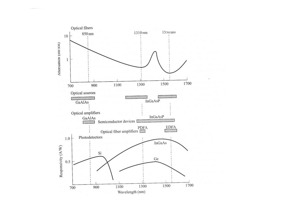
The Evolution of Fiber Optic Systems
First generation operated around 850 nm. Bit rate Mb/s. GaAs-based optical souces, multimode fibers and silicon detectors. Second generation at 1300 nm. Substantial increase in transmission distance and bit rate (622 Mb/s-2.5 Gb/s). Both multimode and single mode fibers were used. First generation system: Repeater spacings of around 10 km. Intermodal dispersion and Fiber loss limited the capacity of these systems. Second generation systems: Transmission systems moved from 850 nm to 1300 nm because of lower loss and less signal dispersion. Repeater spacings of around 40 km.
. Both multimode and single mode fibers were used. First generation system: Repeater spacings of around 10 km. Intermodal dispersion and Fiber loss limited the capacity of these systems. Second generation systems: Transmission systems moved from 850 nm to 1300 nm because of lower loss and less signal dispersion. Repeater spacings of around 40 km.")
10
The Evolution of Fiber Optic Systems
Third generation systems operated around 1550 nm since the fiber 1550 nm is the lowest. But standard fibers have larger dispersion at 1550 nm than at 1300 nm. Fiber manufacturers overcame this limitation by inventing dispersion shifted (DS) fibers. Transmission rates – 2.5 Gb/s to 10 Gb/s. Invention of (Erbium Doped Fiber Amplifier) EDFA revolutionized light wave communication. Wavelength Division Multiplexing (WDM) offered a further boost in transmission capacity Fourth generation systems operated at 1550 nm with EDFA and WDM
 fibers. Transmission rates – 2.5 Gb/s to 10 Gb/s. Invention of (Erbium Doped Fiber Amplifier) EDFA revolutionized light wave communication. Wavelength Division Multiplexing (WDM) offered a further boost in transmission capacity. Fourth generation systems operated at 1550 nm with EDFA and WDM.")
11
The Evolution of Fiber Optic Systems
With the advent of WDM, it was realized that DS fibers were not suitable for long haul transmission because of four wave mixing among different channels of WDM. So, standard fiber (D=17 ps/nm.km) or Non-zero dispersion shifted fiber (NZDSF) are used in current commercial systems. Relatively large dispersion of these fibers is compensated by means of dispersion compensating fibers. Large local dispersion helps to minimize four wave mixing penalty in WDM systems.
 or Non-zero dispersion shifted fiber (NZDSF) are used in current commercial systems. Relatively large dispersion of these fibers is compensated by means of dispersion compensating fibers. Large local dispersion helps to minimize four wave mixing penalty in WDM systems.")
12
Modulation Formats Traditionally non-return-to-zero (NRZ) format is used in optical communication systems. Recently, quasi-linear return-to-zero (RZ), solitons, carrier-suppressed RZ (CS-RZ) and differential phase shift keying (DPSK) have drawn considerable attention. Soliton is a pulse that propagates without change in shape. When the fiber dispersion is balanced by nonlinearity, solitons are formed. Solton is a special case of RZ format. NRZ requires smaller signal bandwidth as compared to RZ because on-off transitions occur fewer times.
, solitons, carrier-suppressed RZ (CS-RZ) and differential phase shift keying (DPSK) have drawn considerable attention. Soliton is a pulse that propagates without change in shape. When the fiber dispersion is balanced by nonlinearity, solitons are formed. Solton is a special case of RZ format. NRZ requires smaller signal bandwidth as compared to RZ because on-off transitions occur fewer times.")
15
Contact Info Instructor: Dr. S. Kumar Office hours: Monday 9-11AM. Office: CRL #219 Web page of the course:

Similar presentations