Download presentation
Presentation is loading. Please wait.

1
Thyristor Structure, Specifications, and Applications
By Miles Pearson 04/17/15 Abstract This presentation will cover the structure, specifications and applications of several different type of thyristors. This will lead into the explanation of all the different modes and regions affiliated with these curves. We will examine the characteristics by taking a look at the I-V curves and construction of mainly the SCR (Silicon Controlled Rectifier). The exploration of certain parameters that limit this device will also be important. Finally, were going to take a look at some specific applications of thyristors and why they are used.
. The exploration of certain parameters that limit this device will also be important. Finally, were going to take a look at some specific applications of thyristors and why they are used.")
2
Overview Expose the main types of thyristors
Different modes of operation Important parameters of the SCR Show construction and characteristics of SCR and TRIAC Applications of thyristors

3
Background On Thyristors
They name Thyristor comes from two similar device names ‘Thyratron’ and ‘Transistor’ Thyristors are useful due to their ability to handle large current in power applications and fast switching The most common thyristor is the SCR which stands for “Silicon Controlled Rectifier”

4
Ultra-High Power Thyristor
Quantitatively understand the upper bound these devices can achieve

5
Main types of thyristors
TRIAC SCR (Silicon Controlled rectifier) TRIAC GTO (Gate Turn Off) IGTO (Integrated Gate Turn Off) MCT (MOS-controlled Rectifier) MCT
 TRIAC. GTO (Gate Turn Off) IGTO (Integrated Gate Turn Off) MCT (MOS-controlled Rectifier) MCT.")
6
Equivalent circuits

7
How the SCR operates Three modes of operation: Reverse Blocking mode
Forward Blocking mode Forward Active conducting mode

8
How the TRIAC Operates Modes of operation:
Forward conducting mode Reverse conducting mode Forward Blocking mode Reverse Blocking mode

9
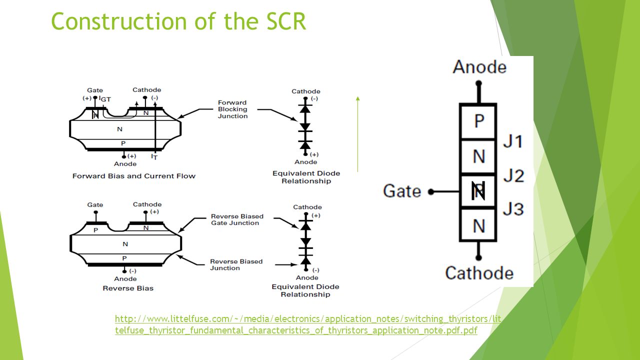
Construction of the SCR
10
Some Important Parameters
di/dt dv/dt – Critical Rise of On-State Current/voltage Maximum rise of current/voltage that the device can handle Things to consider: High frequencies and large amounts of current/voltage Igm Vgm – Forward Peak Gate Current/Voltage Largest amount of current/voltage that can be applied to gate while in conduction mode IH – Holding Current Minimum current flow (from anode to cathode) to keep device on IL – Latching Current Current flow applied to anode in order to turn the device on
 to keep device on. IL – Latching Current. Current flow applied to anode in order to turn the device on.")
11
More parameters… tgt – Gate Turn-On Time tq – Turn-Off Time
Time it takes for a gate pulse to send the SCR into conducting mode or when when the voltage drops giving it negative resistance tq – Turn-Off Time Time it takes for SCR to start blocking current after external voltage has switched to negative cycle VDRM Ileakage – Peak Repetitive Off-State Forward Voltage/current Maximum repetitive voltage/current applied to Anode that wont breakdown the SCR or damage it VRRM IRRM – Peak Repetitive Off-State Reverse Voltage/Current Maximum repetitive voltage/current applied to Cathode that wont breakdown the SCR or damage it

12
Even More Parameters IGT VGT – Gate Trigger Current/Voltage
Minimum value of current/voltage that will trigger the device from off to on Important for considering false triggering I2t – Circuit Fusing Consideration Max non-repetitive over-current capability without damage (typically rated for 60hz) Tj – Junction Temperature Temperature range which this device may operate without damage under load conditions
 Tj – Junction Temperature. Temperature range which this device may operate without damage under load conditions.")
13
http://forum. allaboutcircuits

14
Characteristics of the SCR N- Regions
SCR’s have a high resistive N-base region which forms a junction J2 as shown This region is typically doped with Phosphorus atoms where ND has a range of values from 1013 to 1014 cm-3 This regions thickness generally ranges from 1um to 100um depending on the voltage ratings Thicker N-base region increases forward conducting voltage drop The Cathode region is only 2um-5 um thick and has ND range of 1016 to cm-3

15
Changing D1 and Newly added N-well
Only D1 changing

16
Current Density Map More heat dissipation in the thicker N-base region
Addition of the N-well seems to spread the charge carriers more unformly

17
Characteristics of the SCR P-Regions
High voltage SCRs are generally made by diffusing Al or Ga making it a P-region Typical NA values range from 1015 to 1017 cm-3 These P-regions are generally on the order of um thick

18
Comparing Doping Concentrations
Highest Doping Concentration: Cathode region or n+ Next Highest level of Concentration: Anode and Gate or p Lowest Doping level: Mid N-Base region or n- However, note that this is the thickest

19
Typical Materials Used In SCR
Si - Silicon SiC – Silicon Carbonite GaN – Gallium Nitride C – Carbon P – Phosphorus Al – Aluminum Au – Gold Pl - Platinum Used to create charge carrier recombination sites This slows the switching time but increases forward conducting voltage drop

20
Trade-Offs In Design Forward Blocking Voltage vs. Switching time
Forward Blocking Voltage vs. Forward Voltage Drop during Conduction Mode

21
Applications of Thyristors
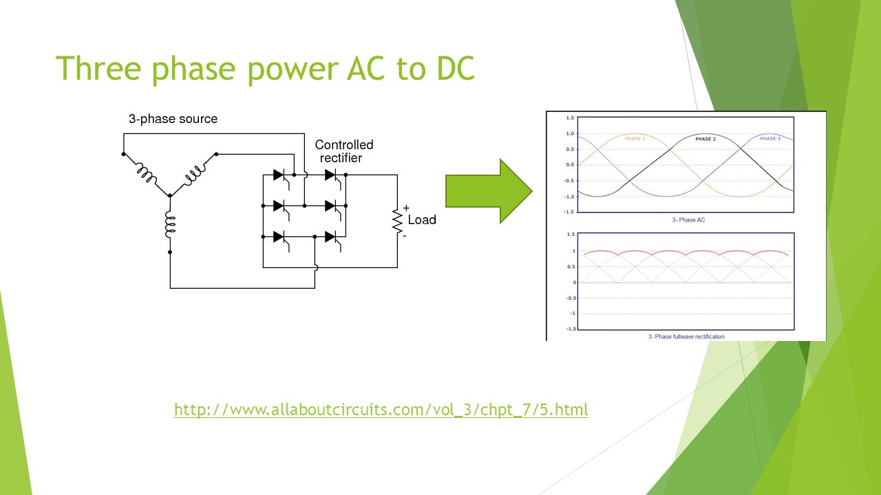
Rectifiers Phase Fired Controllers Light Dimmers Motor Drive Speed Controllers Strobe Lights

22
Three phase power AC to DC
23
Stun Gun Used in Power Project
Pulse rate of about 30-50hz when triggered

24
Conclusion The main types of thyristors specified are the SCR, TRIAC, GTO, and MCT Operation modes for SCR include: Forward Active Conduction, Reverse Blocking, and Forward Blocking Characteristics of the SCR are dependent on large current and voltage Manufacturers strive for a good trade off between forward conducting voltage drop and switching time Applications are mainly centered around control of high current flow

25
Sources Academic Sources:
Greenburg, R., "Consumer applications of power semiconductors," Proceedings of the IEEE , vol.55, no.8, pp.1426,1434, Aug doi: /PROC Shurong Dong; Jian Wu; Meng Miao; Jie Zeng; Yan Han; Liou, J.J., "High-Holding-Voltage Silicon-Controlled Rectifier for ESD Applications," Electron Device Letters, IEEE , vol.33, no.10, pp.1345,1347, Oct doi: /LED Web Content: ristors_application_note.pdf.pdf

26
Concept Check Describe the three modes of operation for SCR and where they relate to the I-V curve Are you able to distinguish between the main types of thyristors specified? What are the significant trade offs in design? What is the difference between latching and holding current? If you change the N-Base region thickness of an SCR how will the resulting forward conducting voltage drop change?

Similar presentations


>")


 state maximum – exhibits.>")
 electrons .... The “extra” electron is NEGATIVELY charged.>")


>")


