Download presentation
Presentation is loading. Please wait.

1
ELECTRIC CIRCUITS ECSE-2010 Spring 2003 Class 13

2
ASSIGNMENTS DUE Today (Tuesday/Wednesday): Will do Experiment #5 in Class (EP-5) Activity 13-1 (In Class) Thursday: Experiment #4 Report Due Will do Experiment #6 in Class (EP-6) Activity 14-1 (In Class) Next Monday: No Classes – President’s Day Next Tuesday: Monday’s Class – All Sections Meet Tuesday
: Will do Experiment #5 in Class (EP-5) Activity 13-1 (In Class) Thursday: Experiment #4 Report Due Will do Experiment #6 in Class (EP-6) Activity 14-1 (In Class) Next Monday: No Classes – President’s Day Next Tuesday: Monday’s Class – All Sections Meet Tuesday")
3
EXAM I Expect to have Exam I graded and returned in class next week Tuesday

4
REVIEW Circuits with C & L : i C = C dv C /dt; v L = L di L /dt DC Steady State: d/dt = 0 => i CSS = 0; v LSS = 0 DC Steady State: C => Open Circuit; L => Open Circuit v C and i L cannot change instantaneously Electrical energy is stored in C and L C and L can interchange electrical energy with the circuit Circuits become far more interesting

5
CAPACITANCE

6
INDUCTANCE

7
SWITCHED CIRCUITS Circuits that Contain Switches Switches Open or Close at t = t 0 t o = Switching Time Often choose t o = 0 Want to Find i’s and v’s in Circuit Before and After Switching Occurs i(t o - ), v(t 0 - ); i(t o + ), v(t 0 + ) Initial Conditions of Circuit
, v(t 0 - ); i(t o + ), v(t 0 + ) Initial Conditions of Circuit")
8
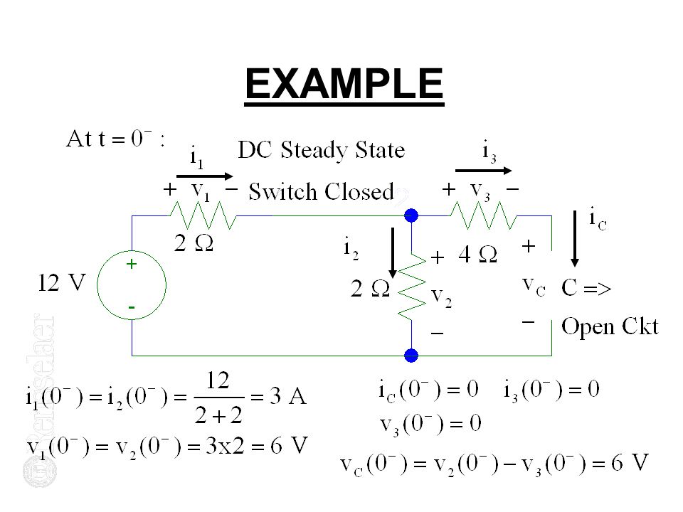
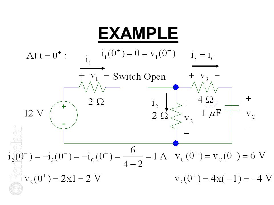
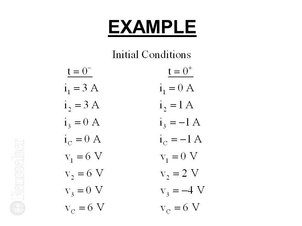
INITIAL CONDITIONS C’s and L’s Store Electrical Energy v C Cannot Change Instantaneously i L Cannot Change Instantaneously In DC Steady State; C => Open Circuit In DC Steady State; L => Short Circuit Use to Find i(t o - ), v(t 0 - ); i(t o + ), v(t 0 + ) Let’s do an Example
, v(t 0 - ); i(t o + ), v(t 0 + ) Let’s do an Example")
9
EXAMPLE

13
1 ST ORDER SWITCHED DC CIRCUITS

14
ACTIVITY 13-1

15
Charge a 20 nF Capacitor to 100 V thru a Variable Resistor, R var : Let’s Use a Switch that Closes at t = 0 R var = 250k, 500k, 1 M Circuit File Has Been Run: C:/Files/Desktop/CE-Studio/Circuits/act_5- 2.dat But Let’s Practice Using Schematics and Take a Quick Look

16
PSPICE WITH C AND L To Describe C and L in Schematics: Capacitor: Use Part Named c Inductor: Use Part Named L Doubleclick on C or L Set Value Set Initial Conditions in Volts and Amps v C (0 + ) and i L (0 + )
 and i L (0 + )")
17
ACTIVITY 13-1 Circuit File v 1 0 dc 100 R 1 2 {R} C 2 0 20n ic=0.param R=250k.step param R list 250k 500k 1meg.tran.1.1 uic.probe.end

18
ACTIVITY 13-1

19
PSPICE TRANSIENTS Transient Analysis – Schematics: Click on Setup Analysis Choose Transient Doubleclick on Transient Choose Print Step =.1 Choose Final Time =.1 Save Click Simulate

20
VARIABLE RESISTOR Schematics: Choose Part = Rvar: Place in Circuit Doubleclick on Rvar Set Value = {Rvar} Change SET to 1.0 Choose Part = Param Doubleclick on Param Set Name1 = Rvar, Value1 = 250k

21
VARIABLE RESISTOR Click on Setup Analysis: Select Parametric Select Global Parameter Select List Set Variable Name = Rvar Set List of Values = 250k 500k 1meg

22
PSPICE WITH C AND L To Describe C and L in Circuit File: C2 4 5 1n IC=3 L4 4 5 3m IC=4u Capacitor Named C2 (Must Start Name with C) Inductor Named L4 (Must Start Name with L) Positive Terminal = Node 4 Negative Terminal = Node 5 Value of C = 1 nanoFarad Value of L = 3 milliHenries v C (0 + ) = 3 Volts; i L (0 + ) = 4 microAmps
 Inductor Named L4 (Must Start Name with L) Positive Terminal = Node 4 Negative Terminal = Node 5 Value of C = 1 nanoFarad Value of L = 3 milliHenries v C (0 + ) = 3 Volts; i L (0 + ) = 4 microAmps")
23
PSPICE TRANSIENTS Transient Analysis – Circuit File:. tran Statement General Form:.tran t p t f uic Start time for Analysis is always t = 0 Print Step Size = t p ; End time = t f Usually Choose t p = t f uic = use initial conditions Must Specify Initial Conditions when describe C and L

24
VARIABLE RESISTOR Circuit File: R 1 2 {R}: Need a.param Statement:.param R = 250k Need a.step Statement.step param R list 250k 500k 1meg

25
OP AMPS WITH R’s AND C’s Can Make Very Useful Circuits by using Capacitors in Op Amp Circuits Replace R F with C in an Inverting Voltage Amplifier: Replace R1 with C in an Inverting Voltage Amplifier:

26
OP AMP INTEGRATOR

27
OP AMP DIFFERENTIATOR

28
OP AMPS WITH R’s AND C’s Replace R F with C in an Inverting Voltage Amplifier: i 1 = v in / R 1 = i c v out = 0 - v c = - v c Interchange R and C:

29
EXPERIMENT 5

30
Use C u in Plastic Box; Unknown C Use Function Generator for v in : Measure v in with Scope, not FG Reading of FG is seldom correct Use 741 Op Amp: Must supply + 5 V and - 5 V for Op Amp: Set voltages independently Handle wires carefully

31
EXPERIMENT 5 Op Amp Differentiator: Input Voltage = Sinusoid:

32
EXPERIMENT 5

33
741 PIN LAYOUT

34
OP AMP PIN LAYOUT

35
MOUNTING OP AMPS 1 2 3 4 8 7 6 5

Similar presentations


 Deadline extended to 5pm Fridays, if.>")


