Download presentation
Presentation is loading. Please wait.

1
POWER SYSTEM PROTECTION AND SWITCHGEARS
EE256

2
Unit I: Introduction Principles and need for protective schemes – Nature and cause of faults – types of fault – per unit representation - Analysis of Symmetrical fault – Current limiting reactors. CTs and PTs and their applications in their protection schemes.

3
Why do we need protection?
Electrical apparatus operates at various voltage levels and may be enclosed or placed in open. Under abnormal operating conditions protection is necessary for Safety of electrical equipments. Safety of human personnel.

4
Why A System Needs Protection?
There is no ‘fault free’ system. It is neither practical nor economical to build a ‘fault free’ system. Electrical system shall tolerate certain degree of faults. Usually faults are caused by breakdown of insulation due to various reasons: system aging, lighting, etc.

5
Purpose of Protection System
Minimize damage Leave unaffected equipment in-service Maintain equipment operating limits Maintain electrical system stability

6
Abnormal conditions: Short circuits in the transmission or distribution line Over voltages due to switching or lightning Over speeding of generators or motors Loss of excitation of machines Over heating of stator and rotor of the machine. Insulation breakdown between the inter-turn coils of the winding Low level oils in the transformer and circuit breakers

7
Nature and causes of faults
Breaking of conductors Failure of insulation Mechanical failure Accidents Excessive internal and external stress High degree of pollution on an insulator string (<insulation strength)
")
8
OH lines-perching of birds
Accidental short circuiting by snakes kite strings Tree branches ice and snow loading Non-system faults, In correct setting Incorrect connection Human error(maintenance)
")
9
Faults and types A fault in a circuit is any failure which interrupts with the normal flow of current. The faults are associated with abnormal change in current, voltage and frequency of the power system. The faults may cause damage to the equipments, if it is allowed to persist for a long time.

10
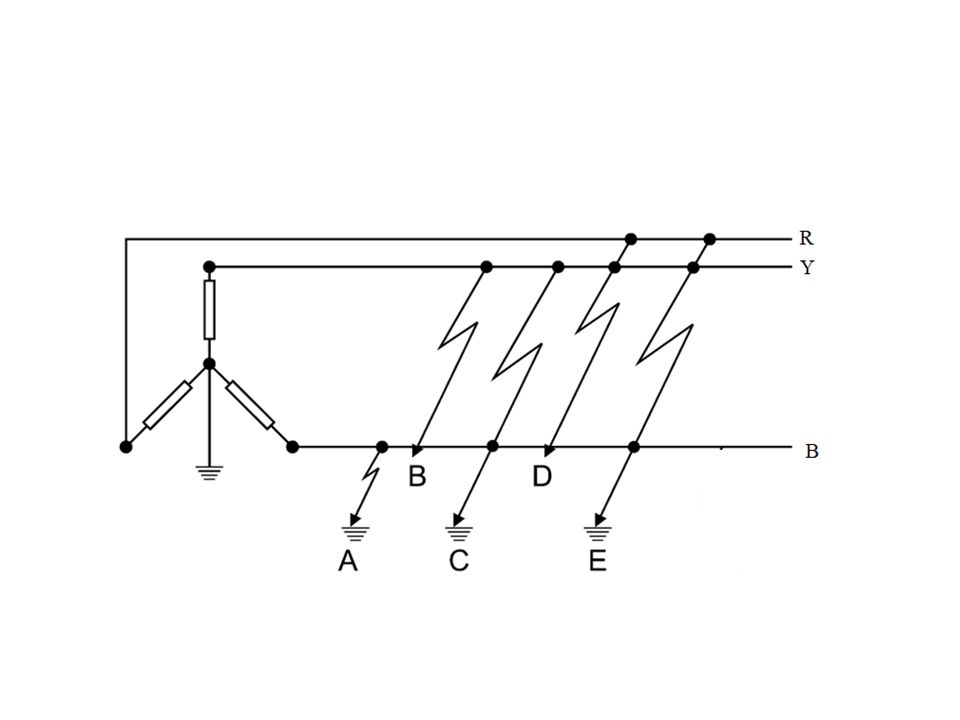
Unsymmetrical faults: short circuit
Faults occur in a power system due to insulation failure of equipments, flashover of lines initiated by a lightening stroke, permanent damage to conductors and towers or accidental faulty operations. Types Symmetrical fault: Three phase fault Unsymmetrical faults: short circuit Single line-to-ground fault Line-to-line fault Double line-to-ground fault Open circuit Single phase open circuit Two phase open circuit Winding faults

11
Sources of Asymmetrical fault are:

13
Effects of faults The fault must be cleared as fast as possible. Many equipments may be destroyed if the fault is not cleared rapidly. The dangerous of the faults depends on the type of the fault, as example the three phase short circuit is the most dangerous fault because the short circuit current is maximum. Some of the effects of short circuit current are listed here under. Due to overheating and the mechanical forces developed by faults, electrical equipments such as bus bars, generators, transformers will be damaged. Negative sequence current arises from unsymmetrical faults will lead to overheating. Voltage profiles may be reduced to unacceptable limits as a result of faults. A frequency drop may lead to instability

14
Fault statistics Element % of total fault OH lines 50 UG cables 9
Transformers 10 Generators 7 Switchgears 12 CTs, PTs, Relays ,Control equipment, etc

15
Per unit representation
In a power system different power equipment with different voltage and power levels are connected together through various step up or step down transformers. However the presence of various voltage and power levels causes problem in finding out the currents (or voltages) at different points in the network. To alleviate this problem, all the system quantities are converted into a uniform normalized platform. This is called the per unit system .
 at different points in the network. To alleviate this problem, all the system quantities are converted into a uniform normalized platform. This is called the per unit system .")
16
In a per unit system each system variable or quantity is
normalized with respect to its own base value. The units of these normalized values are per unit (abbreviated as pu) and not Volt, Ampere or Ohm. The base quantities chosen are: VA base ( Pbase ): This is the three-phase apparent power (Volt-Ampere) base that is common to the entire circuit. Voltage Base ( Vbase ): This is the line-to-line base voltage. This quantity is not uniform for the entire circuit but gets changed by the turns ratio of the transformer.
 and not Volt, Ampere or Ohm. The base quantities. chosen are: VA base ( Pbase ): This is the three-phase apparent power (Volt-Ampere) base that is common to the entire circuit. Voltage Base ( Vbase ): This is the line-to-line base voltage. This quantity is not uniform for the entire circuit but gets changed by the turns ratio of the transformer.")
17
The per unit value of any electrical quantity is defined as the ratio of the actual value of the quantity to its base value expressed as a decimal.

18
Advantages of per unit representation
The per unit impedance referred to either side of a single phase transformer is the same. The per unit impedance referred to either side of a three phase transformer is the same regardless of the three phase connections whether they are Y-Y, Δ-Δ or Δ-Y The chance of confusion between the line and phase quantities in a three phase balanced system is greatly reduced. The manufacturers usually provide the impedance values in per unit. The computational effort in power system is very much reduced with the use of per unit quantities.

19
Reactors Reactors are equipment of transformer family. A reactor has a predominantly inductive coil. Reactors are used in the power system network for current limiting and for compensation of reactive power. There are two types of reactors: Series reactors-connected in series for current limiting Shunt reactors- connected in shunt, for compensation of reactive power.

20
Current limiting reactor
Series Reactors (CLR) are necessary for limiting short circuit currents, for limiting inrush currents while switching-in, for limiting current surges with fluctuating loads, for smoothing the current waveform, for giving stored energy for satisfactory operation of converters, neutral grounding reactors, etc
 are necessary for limiting short circuit currents, for limiting inrush currents while switching-in, for limiting current surges with fluctuating loads, for smoothing the current waveform, for giving stored energy for satisfactory operation of converters, neutral grounding reactors, etc.")
21
Advantages of CLR To limit the flow of short circuit current.
Protect the equipment from over heating as well as failure due to destructive mechanical forces. Increases the chances of continuity of supply. They permit the installation of C.B of lower ratings.

22
Current limiting reactor
These are inserted in series with the line , to limit the current flow in the event of a short circuit.

23
Continue…. Fault current < breaking current capacity- C.B have enough breaking Fault current > breaking current capacity- replace high breaking capacity C.B or put CLR The essential requirements of CLR is that reactance should not reduce due to saturation under short circuit condition.

24
Types: Dry type air core reactor Oil immersed air core reactor Dry type : For moderate voltages (up to 33KV)and power ratings the cheapest type of current limiting reactors is usually the simple naked dry-type reactor iron core and any enclosure, cooled by natural air circulation. The magnitude of the inductance of these reactors is normally in the order of millinery. The inductance remains constant when short circuit flows through the reactor. There is no decline in the inductance due to saturation in an iron core. It occupies large space.

25
The absence of an iron core makes the winding capacitance to earth quite small, which gives the advantage that the voltage distribution within the winding deviates just moderately from linearity during transient voltage conditions. Oil- immersed type: Dry-type reactors for higher voltages may not be suitable in heavily polluted areas because of the risk of dielectric failure. In such cases, oil-immersed reactors might be more reliable. To avoid excessive heating in the tank a frame of laminated core steel must enclose the oil-immersed reactor winding. The dimensioning of the reactor must be such that the inductance is sufficiently large when short circuit current flows through the reactor and when saturation may occur in the core. The cost of an oil-immersed reactor will be considerably higher than of a dry type, while the oil-immersed reactor might be less space consuming.

26
Advantages oil immersed type:
Higher factor of safety against flash over Smaller size High thermal capacity Location of reactors: In series with each generator In series with each feeder In bus-bars

27
What is Instrument Transformer ?
A transformer that is used in conjunction with a measuring instrument. It utilizes the current-transformation and voltage transformation properties to measure high ac current and voltage.

28
Importance of Instrument transformers
In dc circuits for current and voltage measurement we use ammeters and voltmeters. For measurement of high current ,it is usual to use low range ammeter with suitable shunt. For measurement of high voltage, low range voltmeter are used with high resistance connected in series. But for measurement of high A.C. current and voltage we cannot use these methods. We use specially constructed instrument transformers.

29
Types of instrument transformers
These instrument transformers are of two types:- Current transformers Potential transformers

30
Current Transformers Current transformer normally known as c.t. is a step up transformer. These are used with low range ammeter to measure current in high voltage alternating circuits where it is not practical to connect instrument and meters directly to lines. This is step up transformer because when we step up the, voltage increases and current decreases. The current is step down in a known ratio called current ratio.

31
Construction of C.T. C.T. has a primary coil of one or more
turns of thick wire connected in series with the line whose current is to be measured. The secondary consist of large number of turns of fine wire, is connected across the ammeter terminals. Working If a current transformer has primary to secondary current ratio of 100:5 then it step up the voltage 20 times and step down the current 1/20 times of its actual value. If we know the current ratio I1/I2 and the reading of a.c. ammeter, the current can be calculated. Current = ratio × ammeter reading

32
Importance of short ckt.
Ammeter resistance is very low ,the current transformer normally works short circuited. If for any reason the ammeter is taken out of secondary winding then the secondary winding must be short ckted with the help of short ckt switch s. If this is not done, then due to high m.m.f. will set up high flux in the core and it will produces excessive core loss which produce heat and high voltage across the secondary terminals Hence the secondary of current transformer is never left open.

33
Potential transformer
A PT is a step down transformer having many primary turns but few secondary turns. In step down the voltage decreases and current increases, thus voltage can be easily measured by using low range voltmeter. The voltage is stepped down in known ratio called voltage ratio.

34
Construction and working of P.T
A potential transformer has many primary windings but few number of secondary windings that makes it step down transformer. Voltmeter is connected to secondary winding usually voltmeter of 150 v is suitable. Working Primary terminals are connected across the line to which the voltage is to be measured. The voltmeter gives the transformed value of voltage at secondary. The deflection of voltmeter when divided by transformed ratio gives the actual voltage at primary. Line voltage = deflection / trasf. Ratio Where transformation ratio = V2/V1

35
Precaution for P.T. Since the secondary of p.t. is connected to relays, their ratings are usually 40 to 100 Watts. For safety purpose the secondary should be completely insulated from the high voltage primary and should be in addition grounded.

36
Types of P.T. Some types of p.t. are Shell type Dry type Oil type

37
Errors in instrument transformer
There are 2 types of errors Ratio error Phase angle error Ratio error: N1/N2~=I1/I2 ,N1/N2`=V1/V2 because of magnetizing and core loss components of the exciting current. Transformation ratio is not constant but depends upon the load current,powerfactor of load and exciting current of the transformers.

38
For a certain transformer design, the burden capability depends on the value of the short-circuit impedance. A low value for the short-circuit impedance (a high quantity of copper) means a high burden capability and vice versa. The burden capability must always be referred to a certain accuracy class. If 200 VA, class 1 is performed with a certain quantity of copper, the class 0.5 capability is 100 VA with the same quantity of copper, on condition that the turns correction is given values adequate to the two classes. The ratio between accuracy class and burden capability is approximately constant. This constant may be called the “accuracy quality factor” K of the winding

39
Applications Circulating current differential protection
Over current phase fault protection Distance protection

40
Assignment Explain various types of instrument transformer
Analysis of symmetrical fault Date of submission

Similar presentations


 drops. Transformer voltage regulation is defined as:>")


