Download presentation
Presentation is loading. Please wait.

1
Jump, Loop, and Call Instructions
WEEK 2 Jump, Loop, and Call Instructions ET2640 Microprocessors and Microcontrollers

2
ET2640 Microprocessors and Microcontrollers

3
ET2640 Microprocessors and Microcontrollers

4
ET2640 Microprocessors and Microcontrollers

5
ET2640 Microprocessors and Microcontrollers

6
ET2640 Microprocessors and Microcontrollers

7
ET2640 Microprocessors and Microcontrollers
I/O Port Programming ET2640 Microprocessors and Microcontrollers

8
ET2640 Microprocessors and Microcontrollers
Peripherals Know the device peripheral parameters Resolution of data Frequency of measurement Understand the interface issues ET2640 Microprocessors and Microcontrollers

9
ET2640 Microprocessors and Microcontrollers

10
ET2640 Microprocessors and Microcontrollers

11
ET2640 Microprocessors and Microcontrollers

12
ET2640 Microprocessors and Microcontrollers

13
ET2640 Microprocessors and Microcontrollers

14
ET2640 Microprocessors and Microcontrollers

15
ET2640 Microprocessors and Microcontrollers

16
ET2640 Microprocessors and Microcontrollers

17
ET2640 Microprocessors and Microcontrollers

18
ET2640 Microprocessors and Microcontrollers

19
ET2640 Microprocessors and Microcontrollers

20
ET2640 Microprocessors and Microcontrollers

21
COUNTER/TIMER PROGRAMMING IN THE 8051
ET2460 Microcomputers and Microprocessors

22
Outlines List the timers of the 8051 and their associated registers
Describe the various modes of the 8051 timers Program the 8051 timers to generate time delays Program the 8051 counters as event counters

23
PROGRAMMING 8051 TIMERS Timer 0 registers
TL0 ( timer 0 low byte ) TH0 ( timer 0 high byte )
 TH0 ( timer 0 high byte )")
24
Timer 1 registers TL1 ( timer 1 low byte ) TH1 ( timer 1 high byte )
 TH1 ( timer 1 high byte )")
25
TMOD (timer mode) register
 register")
27
Find the timer’s clock frequency and its period for various
8051-based systems, with the following crystal frequencies: 12 mHz 16 mHz mhz

28
ET2640 Microprocessors and Microcontrollers
Oscillator/Clock ET2640 Microprocessors and Microcontrollers

29
Example: Find the value for TMOD if we want to program timer 0 IN MODE 2 USE THE 8051 XTAL for the clock source, and use instructions to start and stop the timer TMOD ;Timer 0, mode 2 C/T=0 to use XTAL clock source, and Gate-0 to use internal software Start and atop method.

30
Mode 1 programming 1.Loaded value into TL and TH
2.”SETB TR0” for timer 0 ;”SETB TR1” for timer 1 3.If TF (timer flag) = high “CLR TR0” or “CLR TR1” 4.Reloaded TH and TL value, TF reset to 0
 = high CLR TR0 or CLR TR1 4.Reloaded TH and TL value, TF reset to 0.")
31
Steps to program in mode 1
1.Load the TMOD value 2.Load registers TL and TH 3.Start the timer (SETB TR0 or SETB TR1) 4.Keep monitoring the timer flag (TF) 5.Stop the timer (CLR TR0 or CLR TR1) 6.Clear the TF flag 7.Go back to step 2
 4.Keep monitoring the timer flag (TF) 5.Stop the timer (CLR TR0 or CLR TR1) 6.Clear the TF flag. 7.Go back to step 2.")
32
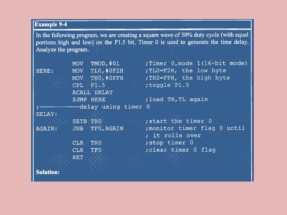
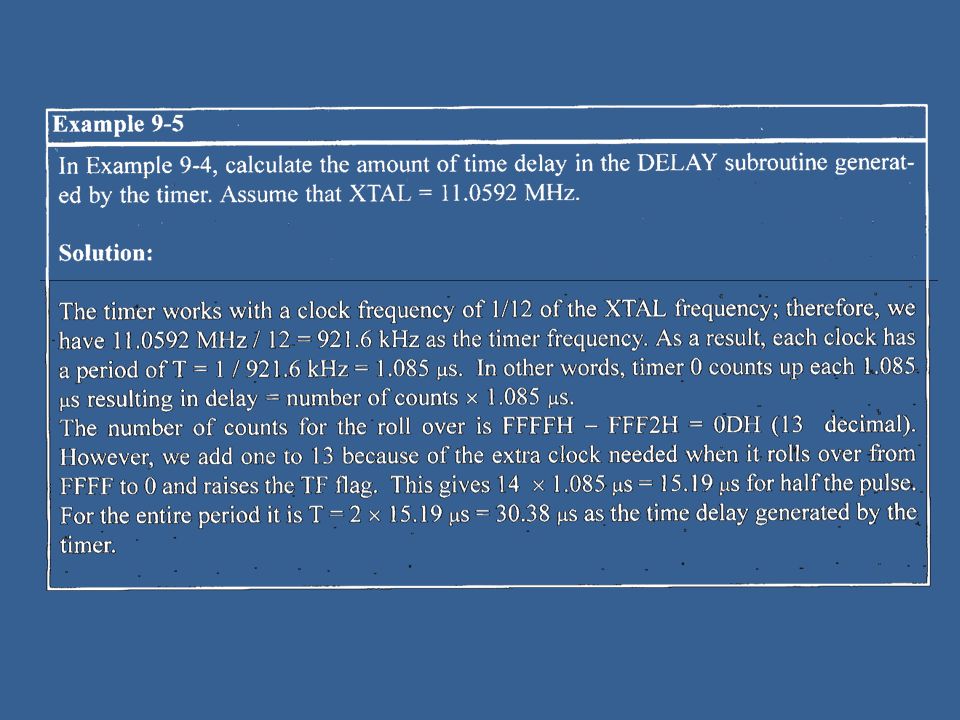
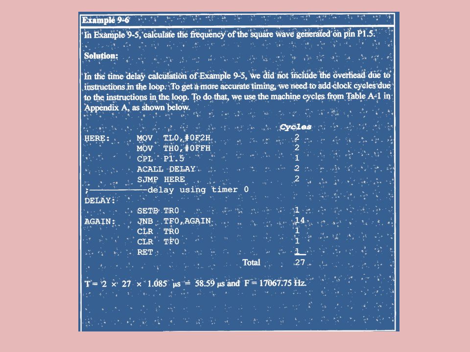
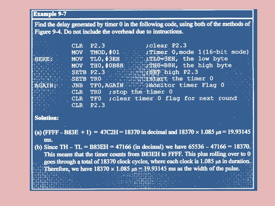
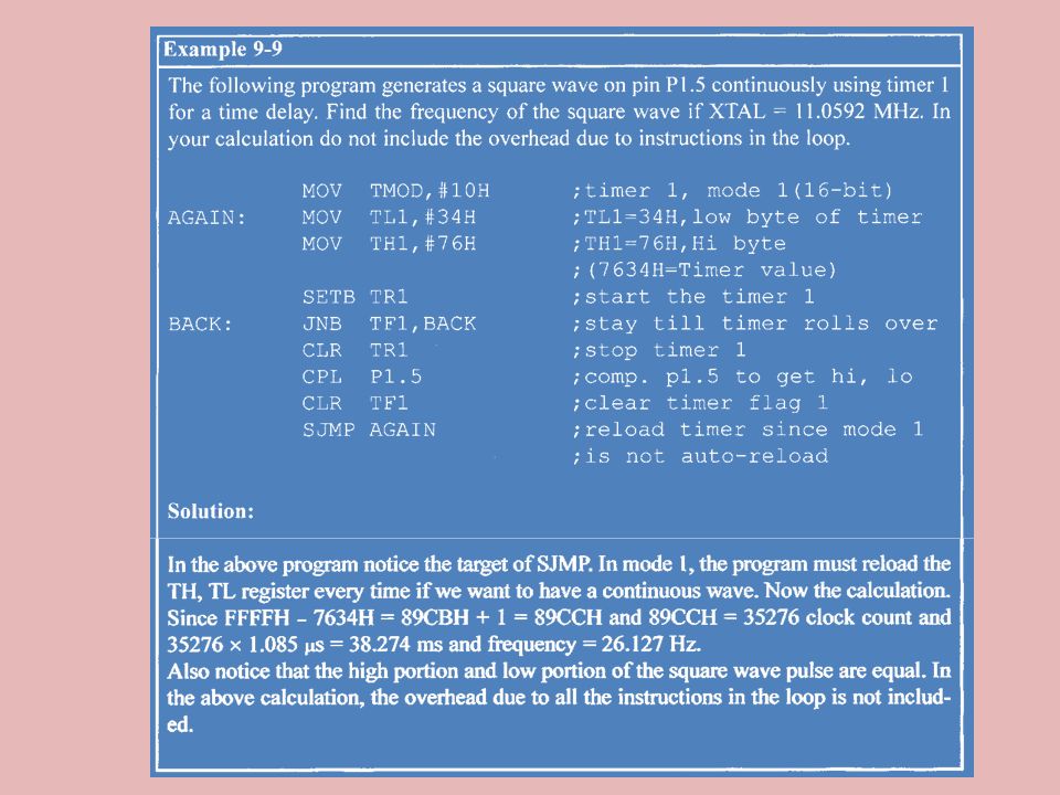
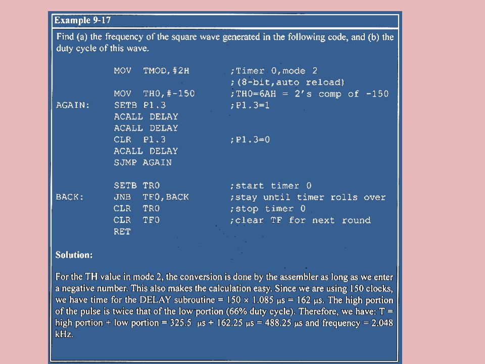
Calculate Timer Delay

40
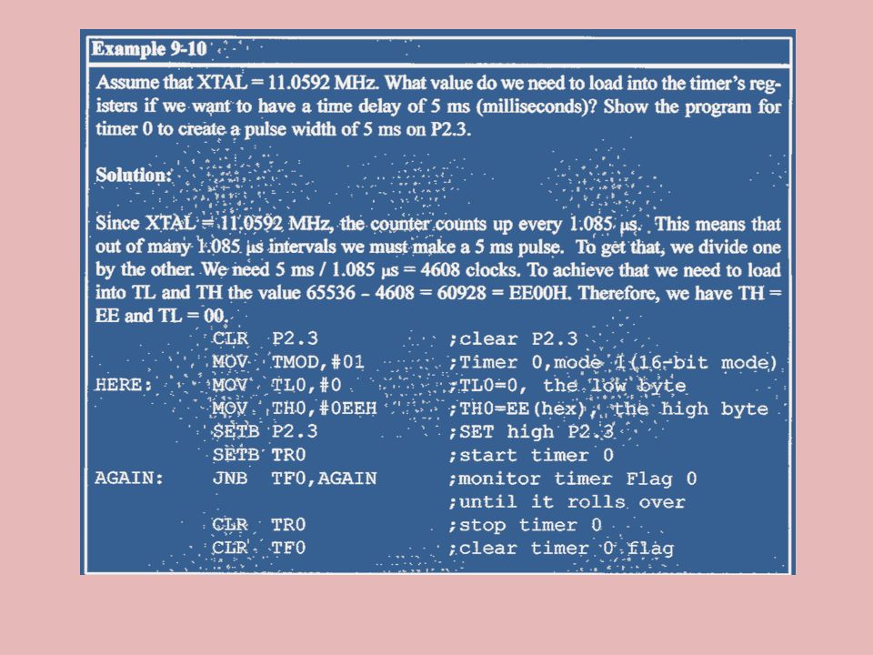
Finding values to be loaded into the timer
Assuming XTAL = MHz from Example 9-10 1.Divide the desired time delay by 1.085μs 2.Perform n, where n is the decimal value we got in Step 1 3.Convert the result of Step 2 to hex, where yyxx is the initial hex value to be loaded into the timer’s registers 4.Set TL = xx and TH = yy

44
Mode 0 Mode 2 Programming Like mode 1 except that it is a 13-bit timer
1.Loaded value into TH (8-bit timer) 2.”SETB TR0” for timer 0 ;”SETB TR1” for timer 1 3.If TF (timer flag) = high “CLR TR0” or “CLR TR1” 4.Reloaded TL value kept by TH
 2. SETB TR0 for timer 0 ; SETB TR1 for timer 1. 3.If TF (timer flag) = high CLR TR0 or CLR TR1 4.Reloaded TL value kept by TH.")
45
Steps to program in Mode 2
1.Load the TMOD value 2.Load the TH registers 3.Start the timer 4.Keep monitoring the timer flag (TF) 5.Clear the TF flag 7.Go back to step 4
 5.Clear the TF flag. 7.Go back to step 4.")
50
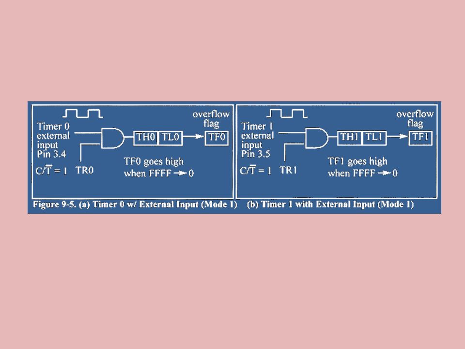
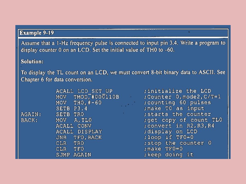
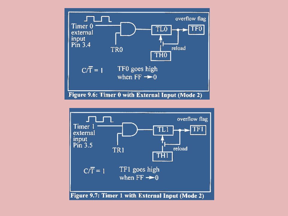
C/T bit in TMOD register

58
The case of GATE =1 in TMOD

Similar presentations