Download presentation
Presentation is loading. Please wait.

1
16.1 Chapter 16 Wireless WANs: Cellular Telephone and Satellite Networks Copyright © The McGraw-Hill Companies, Inc. Permission required for reproduction or display.

2
16.2 16-1 CELLULAR TELEPHONY Cellular telephony is designed to provide communications between two moving units, called mobile stations (MSs), or between one mobile unit and one stationary unit, often called a land unit. Frequency-Reuse Principle Transmitting Receiving Roaming First Generation Second Generation Third Generation Topics discussed in this section:

3
Wireless Communications When? Mobile communications is needed Terrain makes wired communication difficult Communications must be set up quickly Communications must be installed at low cost Same information broadcast to many locations

4
Wireless Disadvantages More susceptible to interference, noise, signal loss, and eavesdropping Generally lower data rate than wired Frequencies interfere in close proximity Less connection stability

5
Cellular Network Organization Multiple low power transmitters 100w or less Area divided into cells Each with own antenna Each with own range of frequencies Served by base station Transmitter, receiver, control unit Adjacent cells on different frequencies to avoid crosstalk

6
Shape of Cells Square Width d cell has four neighbors at distance d and four at distance d Better if all adjacent antennas equidistant Simplifies choosing and switching to new antenna Hexagon Provides equidistant antennas Radius defined as radius of circum-circle Distance from center to vertex equals length of side Distance between centers of cells radius R is R Not always precise hexagons Topographical limitations Local signal propagation conditions Location of antennas

7
Cellular Geometries

8
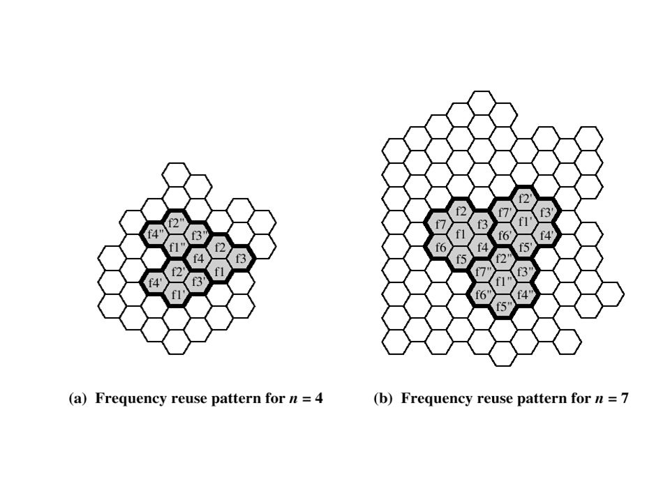
Frequency Reuse Power of base transceiver controlled Allow communications within cell on given frequency Limit escaping power to adjacent cells Allow re-use of frequencies in nearby cells Use same frequency for multiple conversations 10 – 50 frequencies per cell E.g. The pattern consists of N cells K total number of frequencies used in systems Each cell has K/N frequencies Advanced Mobile Phone Service (AMPS) K=395, N=7 giving 57 frequencies per cell on average
 K=395, N=7 giving 57 frequencies per cell on average.")
9
Characterizing Frequency Reuse D = minimum distance between centers of cells that use the same band of frequencies (called cochannels) R = radius of a cell d = distance between centers of adjacent cells (d = R) N = number of cells in repetitious pattern Reuse factor Each cell in pattern uses unique band of frequencies Hexagonal cell pattern, following values of N possible N = I 2 + J 2 + (I x J), I, J = 0, 1, 2, 3, … Possible values of N are 1, 3, 4, 7, 9, 12, 13, 16, 19, 21, … D/R= D/d =
 R = radius of a cell d = distance between centers of adjacent cells (d = R) N = number of cells in repetitious pattern Reuse factor Each cell in pattern uses unique band of frequencies Hexagonal cell pattern, following values of N possible N = I 2 + J 2 + (I x J), I, J = 0, 1, 2, 3, … Possible values of N are 1, 3, 4, 7, 9, 12, 13, 16, 19, 21, … D/R= D/d =")
10
Frequency Reuse Patterns

11
16.11 Figure 16.2 Frequency reuse patterns

12
Increasing Capacity (1) Add new channels Not all channels used to start with Frequency borrowing Taken from adjacent cells by congested cells Or assign frequencies dynamically Cell splitting Non-uniform distribution of topography and traffic Smaller cells in high use areas Original cells 6.5 – 13 km 1.5 km limit in general More frequent handoff More base stations
 Add new channels Not all channels used to start with Frequency borrowing Taken from adjacent cells by congested cells Or assign frequencies dynamically Cell splitting Non-uniform distribution of topography and traffic Smaller cells in high use areas Original cells 6.5 – 13 km 1.5 km limit in general More frequent handoff More base stations")
13
Cell Splitting

14
Increasing Capacity (2) Cell Sectoring Cell divided into wedge shaped sectors 3 – 6 sectors per cell Each with own channel set Subsets of cell’s channels Directional antennas Microcells Move antennas from tops of hills and large buildings to tops of small buildings and sides of large buildings Even lamp posts Form microcells Reduced power Good for city streets, along roads and inside large buildings
 Cell Sectoring Cell divided into wedge shaped sectors 3 – 6 sectors per cell Each with own channel set Subsets of cell’s channels Directional antennas Microcells Move antennas from tops of hills and large buildings to tops of small buildings and sides of large buildings Even lamp posts Form microcells Reduced power Good for city streets, along roads and inside large buildings")
15
N=7, 32 cells, R=1.6km, in total 336 channels

16
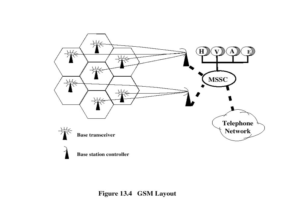
Operation of Cellular Systems Base station (BS) at center of each cell Antenna, controller, transceivers Controller handles call process Number of mobile units may in use at a time BS connected to mobile telecommunications switching office (MTSO) One MTSO serves multiple BS MTSO to BS link by wire or wireless MTSO: Connects calls between mobile units and from mobile to fixed telecommunications network Assigns voice channel Performs handoffs Monitors calls (billing) Fully automated
 at center of each cell Antenna, controller, transceivers Controller handles call process Number of mobile units may in use at a time BS connected to mobile telecommunications switching office (MTSO) One MTSO serves multiple BS MTSO to BS link by wire or wireless MTSO: Connects calls between mobile units and from mobile to fixed telecommunications network Assigns voice channel Performs handoffs Monitors calls (billing) Fully automated")
17
Overview of Cellular System

18
Channels Control channels Setting up and maintaining calls Establish relationship between mobile unit and nearest BS Traffic channels Carry voice and data

19
Typical Call in Single MTSO Area (1) Mobile unit initialization Scan and select strongest set up control channel Automatically selected BS antenna of cell Usually but not always nearest (propagation anomalies) Handshake to identify user and register location Scan repeated to allow for movement Change of cell Mobile unit monitors for pages (see below) Mobile originated call Check set up channel is free Monitor forward channel (from BS) and wait for idle Send number on pre-selected channel Paging MTSO attempts to connect to mobile unit Paging message sent to BSs depending on called mobile number Paging signal transmitted on set up channel
 Mobile unit initialization Scan and select strongest set up control channel Automatically selected BS antenna of cell Usually but not always nearest (propagation anomalies) Handshake to identify user and register location Scan repeated to allow for movement Change of cell Mobile unit monitors for pages (see below) Mobile originated call Check set up channel is free Monitor forward channel (from BS) and wait for idle Send number on pre-selected channel Paging MTSO attempts to connect to mobile unit Paging message sent to BSs depending on called mobile number Paging signal transmitted on set up channel")
20
Typical Call in Single MTSO Area (2) Call accepted Mobile unit recognizes number on set up channel Responds to BS which sends response to MTSO MTSO sets up circuit between calling and called BSs MTSO selects available traffic channel within cells and notifies BSs BSs notify mobile unit of channel Ongoing call Voice/data exchanged through respective BSs and MTSO Handoff Mobile unit moves out of range of cell into range of another cell Traffic channel changes to one assigned to new BS Without interruption of service to user
 Call accepted Mobile unit recognizes number on set up channel Responds to BS which sends response to MTSO MTSO sets up circuit between calling and called BSs MTSO selects available traffic channel within cells and notifies BSs BSs notify mobile unit of channel Ongoing call Voice/data exchanged through respective BSs and MTSO Handoff Mobile unit moves out of range of cell into range of another cell Traffic channel changes to one assigned to new BS Without interruption of service to user")
21
Call Stages

22
Other Functions Call blocking During mobile-initiated call stage, if all traffic channels busy, mobile tries again After number of fails, busy tone returned Call termination User hangs up MTSO informed Traffic channels at two BSs released Call drop BS cannot maintain required signal strength Traffic channel dropped and MTSO informed Calls to/from fixed and remote mobile subscriber MTSO connects to PSTN MTSO can connect mobile user and fixed subscriber via PSTN MTSO can connect to remote MTSO via PSTN or via dedicated lines Can connect mobile user in its area and remote mobile user

23
Mobile Radio Propagation Effects Signal strength Strength of signal between BS and mobile unit strong enough to maintain signal quality at the receiver Not strong enough to create too much cochannel interference Noise varies Automobile ignition noise greater in city than in suburbs Other signal sources vary Signal strength varies as function of distance from BS Signal strength varies dynamically as mobile unit moves Fading Even if signal strength in effective range, signal propagation effects may disrupt the signal

24
Three Generations 1st Generation based on analog voice using frequency modulation 2nd Generation digital techniques and time-division (TDMA) or code-division multiple access (CDMA) 3rd Generation broadband access for personal communications services (PCS)
 or code-division multiple access (CDMA) 3rd Generation broadband access for personal communications services (PCS)")
25
16.25 AMPS is an analog cellular phone system using FDMA. Note

26
16.26 Figure 16.5 Second-generation cellular phone systems

27
Advanced Mobile Phone Service 1st Generation most common mobile phone service since early 80’s developed by AT&T

28
AMPS Spectral Allocation Two 25-MHz bands base to mobile (869-894 MHz) mobile to base (824-849 MHz) Each split in two to allow competition each operator allocated 12.5 MHz bands 416 channels per operator 395 for calls, 21 for control data
 mobile to base ( MHz) Each split in two to allow competition each operator allocated 12.5 MHz bands 416 channels per operator 395 for calls, 21 for control data")
29
16.29 Figure 16.3 Cellular bands for AMPS

30
16.30 Figure 16.4 AMPS reverse communication band

31
AMPS Spatial Allocation Limited channels dictate frequency reuse in nearby cells Generally 10 to 50 frequencies assigned to cell Pattern of 7 cells smallest allowing sufficient isolation 57 frequencies per cell 6.5 to 13 km per cell May be split with lower power

32
16.32 D-AMPS, or IS-136, is a digital cellular phone system using TDMA and FDMA. Note

33
16.33 Figure 16.6 D-AMPS

35
AMPS Components Mobile Units contains a modem that can switch between many frequencies 3 identification numbers: electronic serial number, system ID number, mobile ID number Base Transceiver full-duplex communication with the mobile Mobile Switching Center

36
AMPS Mobile Units Modem that can switch between frequencies Power output of unit controlled to match size of cell Three identification numbers electronic serial number - 32 bits system operator identification number - 15 bits mobile identification number - 34 bits - phone #

37
AMPS Logon When mobile becomes operational, it senses control channels to determine channel and base station received best Exchanges information via base station Announces its system id # to identify its home carrier Home carrier contacted for authorization and to locate mobile for incoming calls

38
AMPS Handoffs Roaming operator must move between cells Different cells have different frequencies and power levels Choice of handoff depends on received power from base stations and controlled by mobile switching center

39
Global System for Mobile Comm. 2nd Generation First appeared in 1991 in Europe Similar to working of AMPS Designed to support phone, data, and image Rates up to 9.6 kbps GSM transmission is encrypted using secret keys

40
Global System for Mobile Communication Developed to provide common 2nd- generation technology for Europe 200 million customers worldwide, almost 5 million in the North America GSM transmission is encrypted Spectral allocation: 25 MHz for base transmission (935–960 MHz), 25 MHz for mobile transmission (890–915 MHz)
, 25 MHz for mobile transmission (890–915 MHz)")
41
GSM SIM Subscriber Identity Module Smart card or plug-in module to activate unit stores subscriber’s identification number networks subscriber is authorized to use encryption keys Can use any unit anywhere with your SIM

43
Multiple Access Four ways to divide the spectrum among active users frequency-division multiplexing (FDM) time-division multiplexing (TDM) code-division multiplexing (CDM) space-division multiplexing (SDM)
 time-division multiplexing (TDM) code-division multiplexing (CDM) space-division multiplexing (SDM)")
44
GSM Access Methods FDM too wasteful TDMA - time-division multiple access early lead - more successful experience CDMA - code-division multiple access theoretical advantages increased range choice for 3rd generation

45
16.45 Figure 16.7 GSM bands

46
16.46 Figure 16.8 GSM

47
16.47 Figure 16.9 Multiframe components

48
16.48 GSM is a digital cellular phone system using TDMA and FDMA. Note

49
16.49 Figure 16.10 IS-95 forward transmission

50
16.50 Figure 16.11 IS-95 reverse transmission

51
16.51 IS-95 is a digital cellular phone system using CDMA/DSSS and FDMA. Note

52
Choice of Access Methods FDM, used in 1st generation systems, wastes spectrum Debate over TDMA vs CDMA for 2nd generation TDMA advocates argue there is more successful experience with TDMA. CDMA proponents argue that CDMA offers additional features as well, such as increased range. TDMA systems have achieved an early lead in actual implementations CDMA seems to be the access method of choice for third- generation systems

53
3rd Generation Wireless Provide high speed wireless for voice, data, video and multimedia ITU’s view voice quality of wired 144 kbps high-speed roaming / 384 kbps low-speed adaptive interface to internet for asymmetric speed more efficient use of spectrum support wide variety of equipment, services, etc

54
PCS & PCN Personal Communications Services (PCS) find person easily use communication system anywhere with single account Personal Communications Network (PCN) use terminal in wide variety of environments to connect to information services
 find person easily use communication system anywhere with single account Personal Communications Network (PCN) use terminal in wide variety of environments to connect to information services")
55
WAP Wireless Application Protocol universal, open standard - WAP forum provide mobile users access to information services, including internet and web Works with wireless network technologies Based on existing internet standards such as TCP, IP, HTTP, HTML, XML Support limited resources in and variety of mobile devices

56
WAP Specs Include programming model Wireless Markup Language (adhering to XML) Microbrowser Lightweight protocol stack Framework for wireless telephony applications
 Microbrowser Lightweight protocol stack Framework for wireless telephony applications")
57
16.57 The main goal of third-generation cellular telephony is to provide universal personal communication. Note

58
16.58 Figure 16.12 IMT-2000 radio interfaces

59
16.59 16-2 SATELLITE NETWORKS A satellite network is a combination of nodes, some of which are satellites, that provides communication from one point on the Earth to another. A node in the network can be a satellite, an Earth station, or an end- user terminal or telephone. Orbits Footprint Three Categories of Satellites GEO Satellites MEO Satellites LEO Satellites Topics discussed in this section:

60
16.60 Figure 16.13 Satellite orbits

61
16.61 What is the period of the Moon, according to Kepler’s law? Example 16.1 Here C is a constant approximately equal to 1/100. The period is in seconds and the distance in kilometers.

62
16.62 Example 16.1 (continued) Solution The Moon is located approximately 384,000 km above the Earth. The radius of the Earth is 6378 km. Applying the formula, we get.

63
16.63 According to Kepler’s law, what is the period of a satellite that is located at an orbit approximately 35,786 km above the Earth? Example 16.2 Solution Applying the formula, we get

64
16.64 This means that a satellite located at 35,786 km has a period of 24 h, which is the same as the rotation period of the Earth. A satellite like this is said to be stationary to the Earth. The orbit, as we will see, is called a geosynchronous orbit. Example 16.2 (continued)
.")
65
16.65 Figure 16.14 Satellite categories

66
16.66 Figure 16.15 Satellite orbit altitudes

67
16.67 Table 16.1 Satellite frequency bands

68
16.68 Figure 16.16 Satellites in geostationary orbit

69
16.69 Figure 16.17 Orbits for global positioning system (GPS) satellites
 satellites")
70
16.70 Figure 16.18 Trilateration

71
16.71 Figure 16.19 LEO satellite system

72
16.72 Figure 16.20 Iridium constellation

73
16.73 The Iridium system has 66 satellites in six LEO orbits, each at an altitude of 750 km. Note

74
16.74 Iridium is designed to provide direct worldwide voice and data communication using handheld terminals, a service similar to cellular telephony but on a global scale. Note

75
16.75 Figure 16.20 Teledesic

76
16.76 Teledesic has 288 satellites in 12 LEO orbits, each at an altitude of 1350 km. Note

Similar presentations


 Ian F. Akyildiz Broadband & Wireless Networking Laboratory School of Electrical and Computer Engineering.>")


