Download presentation
Presentation is loading. Please wait.

1
UML Part 1: Class Diagrams

2
Introduction UML stands for Unified Modeling Language. It represents a unification of the concepts and notations presented by the three amigos in their respective books. The goal is for UML to become a common language for creating models of object oriented computer software.

3
Class Diagrams. The purpose of a class diagram is to depict the classes within a model. In an object oriented application, classes have attributes (member variables), operations (member functions) and relationships with other classes. The UML class diagram can depict all these things quite easily.
, operations (member functions) and relationships with other classes. The UML class diagram can depict all these things quite easily..")
4
The fundamental element of the class diagram is an icon the represents a class. This icon is shown in Figure 1.

5
Fig 1.

6
A class icon is simply a rectangle divided into three compartments. The topmost compartment contains the name of the class. The middle compartment contains a list of attributes (member variables), and the bottom compartment contains a list of operations (member functions). In many (but not all) diagrams, the bottom two compartments are omitted. Even when they are present, they typically do not show every attribute and operations. The goal is to show only those attributes and operations that are useful for the particular diagram.
, and the bottom compartment contains a list of operations (member functions). In many (but not all) diagrams, the bottom two compartments are omitted. Even when they are present, they typically do not show every attribute and operations. The goal is to show only those attributes and operations that are useful for the particular diagram..")
7
This ability to abbreviate an icon is one of the hallmarks of UML. Each diagram has a particular purpose. That purpose may be to highlight on particular part of the system, or it may be to illuminate the system in general. The class icons in such diagrams are abbreviated as necessary. There is typically never a need to show every attribute and operation of a class on any diagram. Figure 2 shows a typical UML description of a class that represents a circle.

8
Figure 2: Circle class

9
Notice that each member variable is followed by a colon and by the type of the variable. If the type is redundant, or otherwise unnecessary, it can be omitted. Notice also that the return values follow the member functions in a similar fashion. Again, these can be omitted. Finally, notice that the member function arguments are just types. I could have named them too, and used colons to separate them from their types; or I could have omitted the arguments altogether.

10
Composition Relationships Each instance of type Circle seems to contain an instance of type Point. This is a relationship known as composition. It can be depicted in UML using a class relationship. Figure 3 shows the composition relationship.

11
Fig 3: Composition relationship

12
The black diamond represents composition. It is placed on the Circle class because it is the Circle that is composed of a Point. The arrowhead on the other end of the relationship denotes that the relationship is navigable in only one direction. That is, Point does not know about Circle.

13
In UML relationships are presumed to be bidirectional unless the arrowhead is present to restrict them. Had I omitted the arrowhead, it would have meant that Point knew about Circle. At the code level, this would imply a #include “circle.h” within point.h. For this reason, I tend to use a lot of arrowheads

14
Composition relationships are a strong form of containment or aggregation. Aggregation is a whole/part relationship. In this case, Circle is the whole, and Point is part of Circle. However, composition is more than just aggregation.

15
Composition also indicates that the lifetime of Point is dependent upon Circle. This means that if Circle is destroyed, Point will be destroyed with it. For those of you who are familiar with the Booch-94 notation, this is the Hasby-value relationship.

16
In C++ we would represent this as shown in Listing 1.

17
Listing 1: Circle class

18
In this case we have represented the composition relationship as a member variable. We could also have used a pointer so long as the destructor of Circle deleted the pointer.

19
Inheritance The inheritance relationship in UML is depicted by a peculiar triangular arrowhead. This arrowhead, that looks rather like a slice of pizza, points to the base class. One or more lines proceed from the base of the arrowhead connecting it to the derived classes.

20
Figure 4 shows the form of the inheritance relationship. In this diagram we see that Circle and Square both derive from Shape. Note that the name of class Shape is shown in italics. This indicates that Shape is an abstract class. Note also that the operations, Draw() and Erase() are also shown in italics. This indicates that they are pure virtual.
 and Erase() are also shown in italics. This indicates that they are pure virtual..")
21
Fig 4

22
Italics are not always very easy to see. Therefore, as shown in Figure 4, an abstract class can also be marked with the {abstract} property. What’s more, though it is not a standard part of UML, I will often write Draw()=0 in the operations compartment to denote a pure virtual function.
=0 in the operations compartment to denote a pure virtual function..")
23
Aggregation / Association The weak form of aggregation is denoted with an open diamond. This relationship denotes that the aggregate class (the class with the white diamond touching it) is in some way the “whole”, and the other class in the relationship is somehow “part” of that whole.
 is in some way the whole , and the other class in the relationship is somehow part of that whole..")
24
Fig 5

25
Figure 5 shows an aggregation relationship. In this case, the Window class contains many Shape instances. In UML the ends of a relationship are referred to as its “roles”. Notice that the role at the Shape end of the aggregation is marked with a “*”.

26
This indicates that the Window contains many Shape instances. Notice also that the role has been named. This is the name that Window knows its Shape instances by. i.e. it is the name of the instance variable within Window that holds all the Shapes.

27
Listing 2 shows how Figure 5 might be implemented in C++

28
Listing 2

29
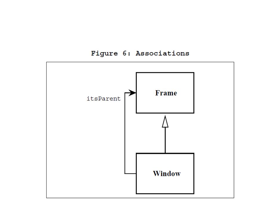
There are other forms of containment that do not have whole / part implications. For example, each Window refers back to its parent Frame. This is not aggregation since it is not reasonable to consider a parent Frame to be part of a child Window. We use the association relationship to depict this.

31
Figure 6 shows how we draw an association. An association is nothing but a line drawn between the participating classes. In Figure 6 the association has an arrowhead to denote that Frame does not know anything about Window. Once again note the name on the role. This relationship will almost certainly be implemented with a pointer of some kind.

32
What is the difference between an aggregation and an association? The difference is one of implication. Aggregation denotes whole/part relationships whereas associations do not. However, there is not likely to be much difference in the way that the two relationships are implemented.

33
That is, it would be very difficult to look at the code and determine whether a particular relationship ought to be aggregation or association. For this reason, it is pretty safe to ignore the aggregation relationship altogether. As the amigos said in the UML 0.8 document: “...if you don’t understand [aggregation] don’t use it.”

34
Aggregation and Association both correspond to the Has-by-reference relationship from the Booch-94 notation.

35
Dependency Sometimes the relationship between a two classes is very weak. They are not implemented with member variables at all. Rather they might be implemented as member function arguments. Consider, for example, the Draw function of the Shape class. Suppose that this function takes an argument of type DrawingContext.

36
Fig 7.

37
Figure 7 shows a dashed arrow between the Shape class and the DrawingContext class. This is the dependency relationship. In Booch94 this was called a ‘using’ relationship. This relationship simply means that Shape somehow depends upon DrawingContext.

38
In C++ this almost always results in a #include.

Similar presentations
![Unified Modeling Language (UML) (Chapter 6). Unified Modeling Language UML October 1994 Three Amigos Grady Booch (Rational Software) [Booch] James.](/13/4175153/big_thumb.jpg "Unified Modeling Language (UML) (Chapter 6). Unified Modeling Language UML October 1994 Three Amigos Grady Booch (Rational Software) [Booch] James.>")

 and Stevens and Pooley.>")


 Karlstad University Dept. of Computer Science 2000-05-09 UML introduction A short introduction.>")


, and widely used in OO analysis and design A modeling language is a.>")
 objectData and operations (functions) are combined >")


 Class Diagrams.>")