Download presentation
Presentation is loading. Please wait.

1
HW# 2 /Tutorial # 2 WRF Chapter 16; WWWR Chapter 17 ID Chapter 3 Tutorial #2 WRF#16.2;WWWR#17.13, WRF#16.1; WRF#16.12; WRF#17.39; WRF#16.22. To be discussed during the week 25 Jan. – 29 Jan., 2016. By either volunteer or class list. Homework # 2 (Self practice) WWWR #17.15, 17.26 ID # 3.57
 WWWR #17.15, ID #")
2
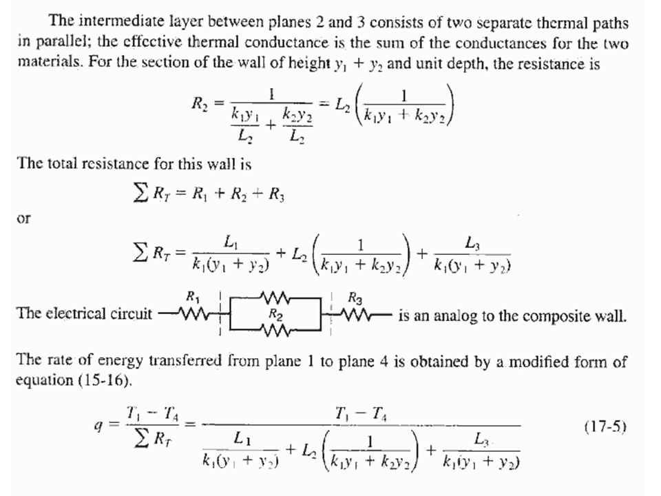
HW# 2 /Tutorial # 2 Hints / Corrections Tutorial #2 WWWR #17.39: Line 2: The fins are made of aluminum, they are 0.3cm thick each. Homework # 2 WWWR #17.15: You may model the whole heat transfer process as the series/parallel connection of 5 resistors: R1 internal convective transfer + R2: Plaster + R3 (Pine Studs) and R4 (Fiberglass) in parallel + R5: External convective transfer. The problem does not specify which is the “inside” and which is the “outside”. Please fix the side next to the plaster to be the inside (R1: hence a temperature of 25 o C is maintained here) and the opposite side to be outside (R5: a temperature of -10 degree C is specified here). # 17.26: Generate heat uniformly at a rate of 5170 kJ/sm 3. the fuel is placed in an environment having a temperature of 370K.
 and R4 (Fiberglass) in parallel + R5: External convective transfer. The problem does not specify which is the inside and which is the outside . Please fix the side next to the plaster to be the inside (R1: hence a temperature of 25 o C is maintained here) and the opposite side to be outside (R5: a temperature of -10 degree C is specified here). # 17.26: Generate heat uniformly at a rate of 5170 kJ/sm 3. the fuel is placed in an environment having a temperature of 370K..")
3
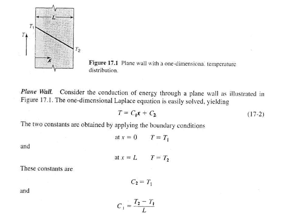
Steady-State Conduction

4
One-Dimensional Conduction Steady-state conduction, no internal generation of energy For one-dimensional, steady-state transfer by conduction i = 0 rectangular coordinates i = 1 cylindrical coordinates i = 2 spherical coordinates

10
1/Rc=1/Ra+1/Rb

16
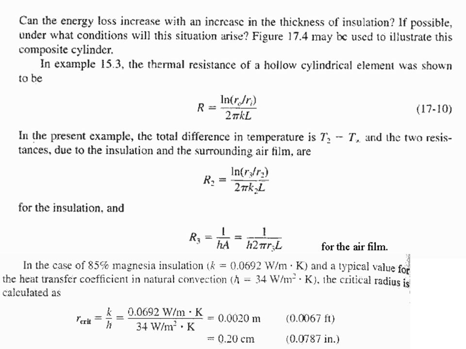
Adapted from Heat and Mass Transfer – A Practical Approach, Y.A. Cengel, Third Edition, McGraw Hill 2007. Thus, insulating the pipe may actually increase the rate of heat transfer instead of decreasing it.

19
For steady-state conduction in the x direction without internal generation of energy, the equation which applies is Where k may be a function of T. In many cases the thermal conductivity may be a linear function temperature over a considerable range. The equation of such a straight-line function may be expressed by k = k o (1 + ßT) Where k o and ß are constants for a particular material
 Where k o and ß are constants for a particular material.")
20
One-Dimensional Conduction With Internal Generation of Energy

23
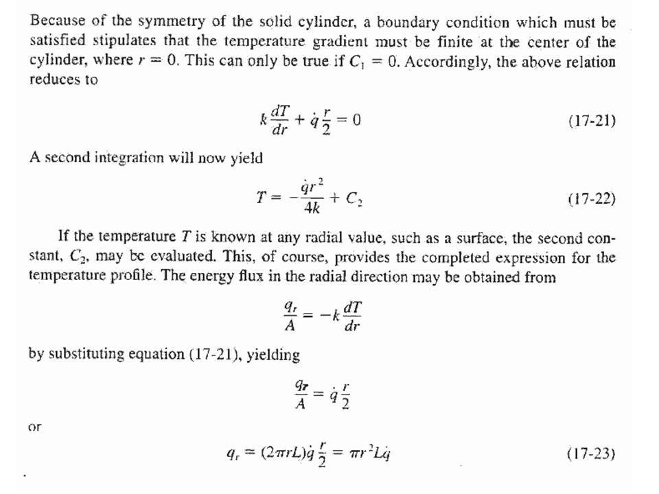
Plane Wall with Variable Energy Generation q = q L [ 1 + ß (T - T L )]. The symmetry of the temperature distribution requires a zero temperature gradient at x = 0. The case of steady-state conduction in the x direction in a stationary solid with constant thermal conductivity becomes
![Plane Wall with Variable Energy Generation q = q L [ 1 + ß (T - T L )].](http://images.slideplayer.com/27/9189988/slides/slide_23.jpg "The symmetry of the temperature distribution requires a zero temperature gradient at x = 0. The case of steady-state conduction in the x direction in a stationary solid with constant thermal conductivity becomes.")
26
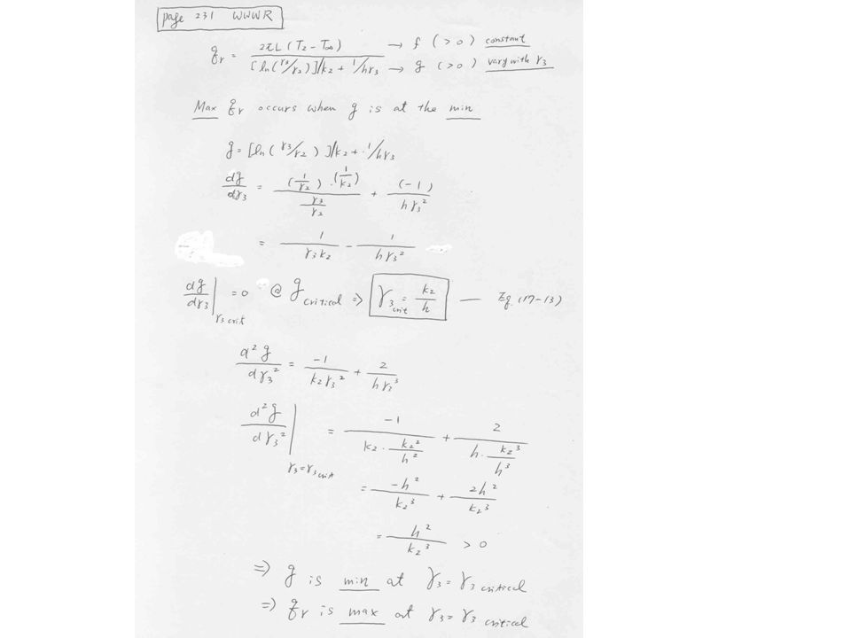
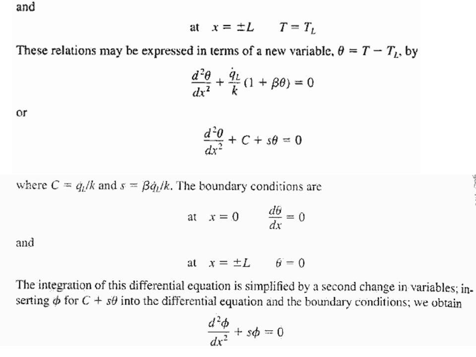
Detailed derivation for the transformation = C + s

28
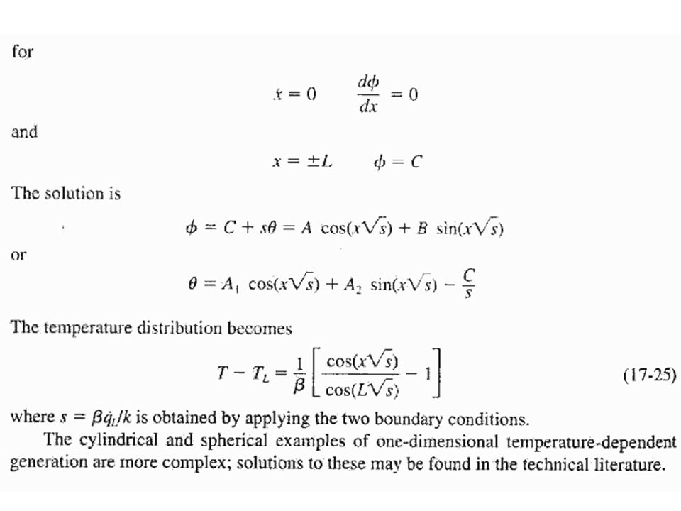
Detailed Derivation for Equations 17-25 Courtesy by all CN5 Grace Mok, 2003-2004

29
Detailed Derivation for Equations 17-25 Courtesy by all CN5 Grace Mok, 2003-2004

30
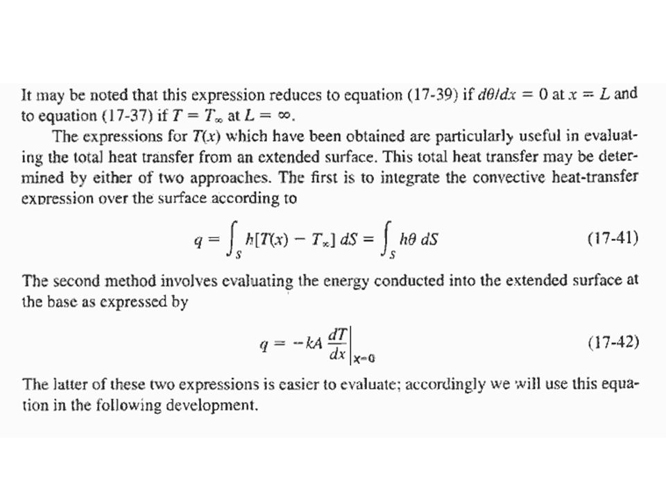
Heat Transfer from Finned Surfaces Temperature gradient dT/dx, Surface temperature, T, Are expressed such that T is a function of x only. Newton’s law of cooling Two ways to increase the rate of heat transfer: –increasing the heat transfer coefficient, –increase the surface area fins Fins are the topic of this section. Adapted from Heat and Mass Transfer – A Practical Approach, Y.A. Cengel, Third Edition, McGraw Hill 2007.

31
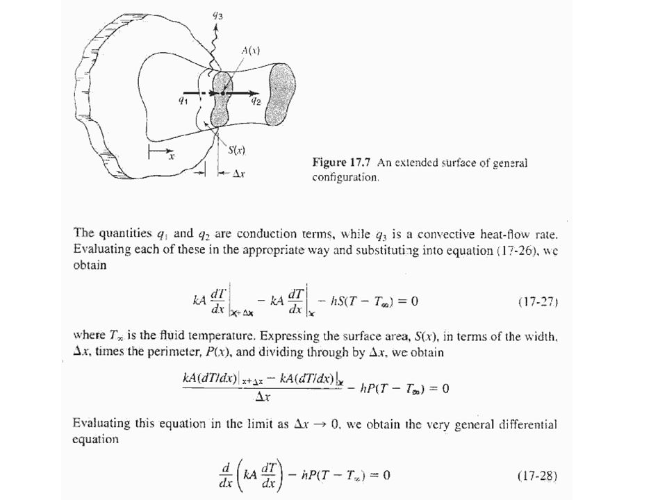
Heat transfer from extended surfaces

33
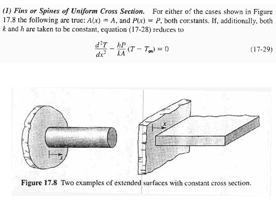
For constant cross section and constant thermal conductivity Where Equation (A) is a linear, homogeneous, second-order differential equation with constant coefficients. The general solution of Eq. (A) is C 1 and C 2 are constants whose values are to be determined from the boundary conditions at the base and at the tip of the fin. (A) (B)
 is C 1 and C 2 are constants whose values are to be determined from the boundary conditions at the base and at the tip of the fin. (A) (B).")
34
Boundary Conditions Several boundary conditions are typically employed: At the fin base –Specified temperature boundary condition, expressed as: (0)= b = T b -T ∞ At the fin tip 1.Specified temperature 2.Infinitely Long Fin 3.Adiabatic tip 4.Convection (and combined convection). Adapted from Heat and Mass Transfer – A Practical Approach, Y.A. Cengel, Third Edition, McGraw Hill 2007.

38
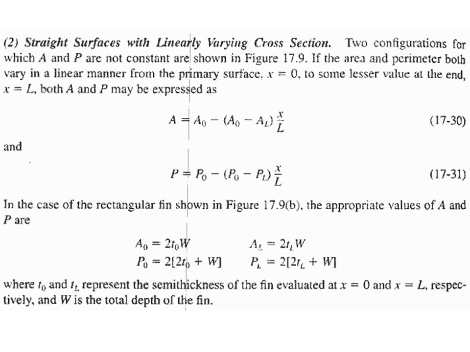
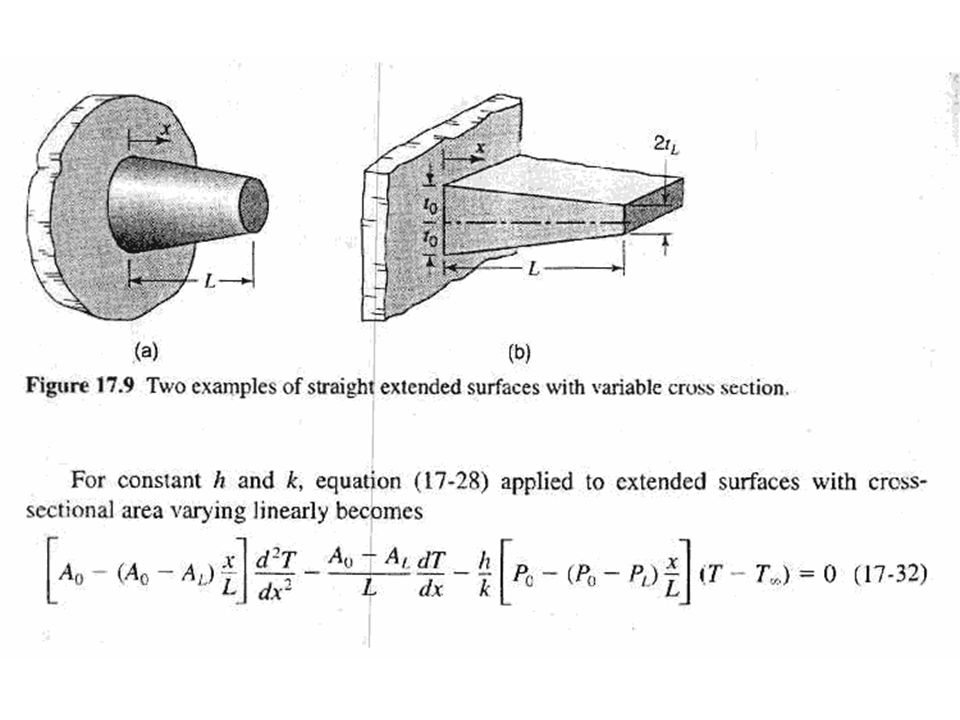
How to derive the functional dependence of for a straight fin with variable cross section area Ac = A = A(x)?
")
39
General Solution for Straight Fin with Three Different Boundary Conditions

40
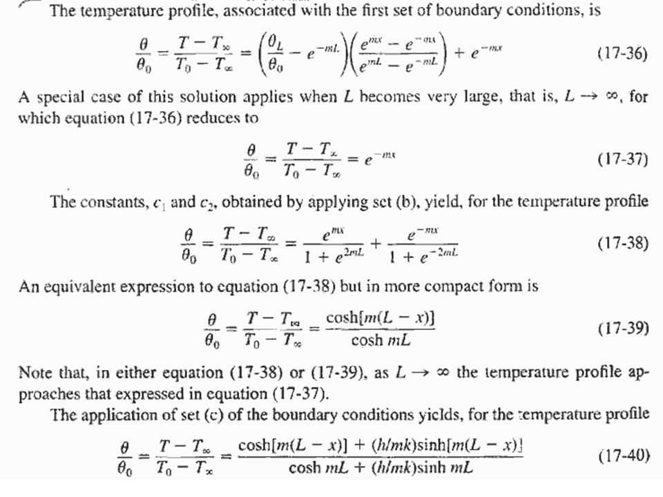
In set(a) Known temperature at x = L In set(b) Temperature gradient is zero at x = L In set(c) Heat flow to the end of an extended surface by conduction be equal to that leaving this position by convection.
 Known temperature at x = L In set(b) Temperature gradient is zero at x = L In set(c) Heat flow to the end of an extended surface by conduction be equal to that leaving this position by convection.")
43
Detailed Derivation for Equations 17-36 (Case a). Courtesy by CN3 Yeong Sai Hooi 2002-2003
. Courtesy by CN3 Yeong Sai Hooi")
44
Detailed Derivation for Equations 17-38 (Case b for extended surface heat transfer). Courtesy by CN3 Yeong Sai Hooi, 2002-2003

45
Detailed Derivation for Equations 17-40 (Case c for extended surface heat transfer). Courtesy by all CN4 students, presented by Loo Huiyun, 2002-2003

48
Detailed Derivation for Equations 17-46 (Case c for extended surface heat transfer). Courtesy by all CN4 students, presented by Loo Huiyun, 2002-2003

49
Infinitely Long Fin (T fin tip =T) Adapted from Heat and Mass Transfer – A Practical Approach, Y.A. Cengel, Third Edition, McGraw Hill 2007. For a sufficiently long fin the temperature at the fin tip approaches the ambient temperature Boundary condition: (L→∞)=T(L)-T ∞ =0 When x→∞ so does e mx →∞ C 1 =0 @ x=0: e mx =1C 2 = b The temperature distribution: heat transfer from the entire fin
=T(L)-T ∞ =0 When x→∞ so does e mx →∞ C 1 x=0: e mx =1C 2 = b The temperature distribution: heat transfer from the entire fin.")
50
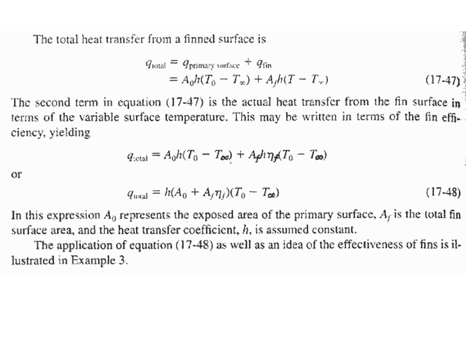
Fin Efficiency Adapted from Heat and Mass Transfer – A Practical Approach, Y.A. Cengel, Third Edition, McGraw Hill 2007. To maximize the heat transfer from a fin the temperature of the fin should be uniform (maximized) at the base value of T b In reality, the temperature drops along the fin, and thus the heat transfer from the fin is less To account for the effect we define a fin efficiency or Actual heat transfer rate from the fin Ideal heat transfer rate from the fin if the entire fin were at base temperature
 at the base value of T b In reality, the temperature drops along the fin, and thus the heat transfer from the fin is less To account for the effect we define a fin efficiency or Actual heat transfer rate from the fin Ideal heat transfer rate from the fin if the entire fin were at base temperature.")
51
Fin Efficiency Adapted from Heat and Mass Transfer – A Practical Approach, Y.A. Cengel, Third Edition, McGraw Hill 2007. For constant cross section of very long fins: For constant cross section with adiabatic tip: A fin = P*L

52
q

53
Fin Effectiveness Adapted from Heat and Mass Transfer – A Practical Approach, Y.A. Cengel, Third Edition, McGraw Hill 2007. The performance of the fins is judged on the basis of the enhancement in heat transfer relative to the no-fin case. The performance of fins is expressed in terms of the fin effectiveness fin defined as Heat transfer rate from the surface of area A b Heat transfer rate from the fin of base area A b

55
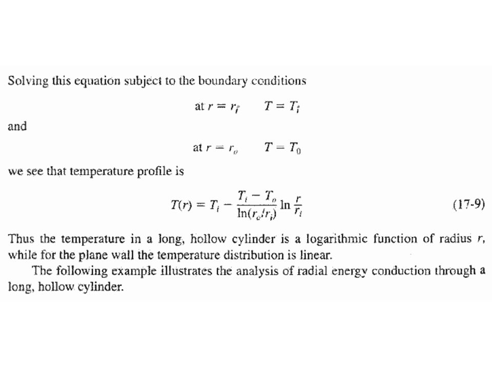
Governing Differential Equation for Circular Fin: Temperature variation in the R (radial) direction only! T = T(r)
.")
56
(R L -R o )
")
58
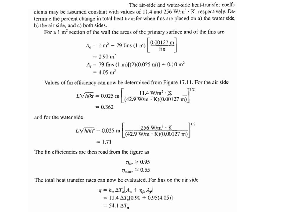
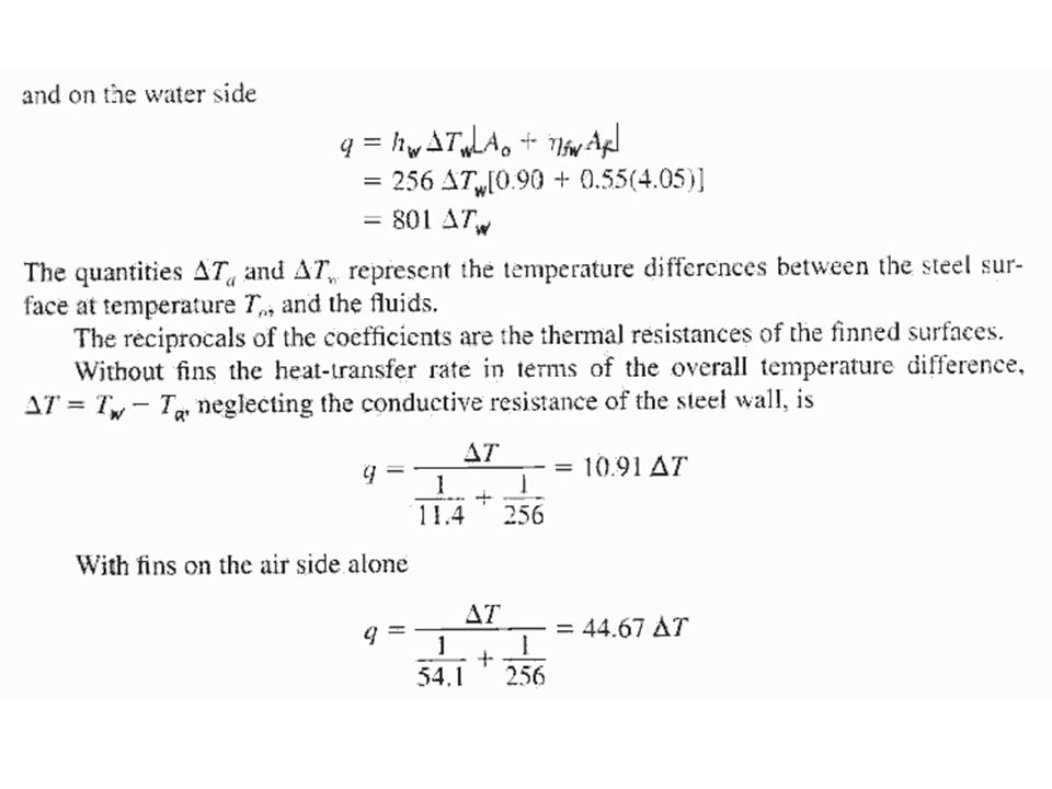
Problem: Water and air are separated by a mild-steel plane wall. I is proposed to increase the heat-transfer rate between these fluids by adding Straight rectangular fins of 1.27mm thickness, and 2.5-cm length, spaced 1.27 cm apart.

62
Two and Three - Dimensional Systems Analytical Solution Analytical solution to any transfer problem must satisfy the differential equation describing the process Prescribed boundary conditions

63
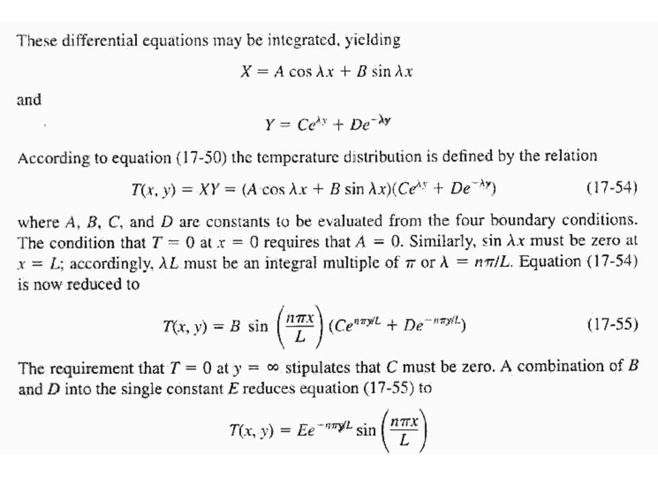
The steady-state temperature distribution in the plate of constant thermal conductivity must satisfy the differential equation

64
We obtain an expression in which the variables are separated

66
(17-57)
")
67
Detailed Derivation for Equations 17-57 Courtesy by all CN6 Leow Sheue Ling, 2003-2004

Similar presentations


 (Section 3.5 – Textbook) 3.1 Implications of energy generation Involve.>")


 fin of rectangular profile is attached to the outer surface of a circular tube having an outside.>")


