Download presentation
Presentation is loading. Please wait.

1
FREQUENCY-POWER CHARACTERISTICS OF SYNCHRONOUS GENERATOR

5
James Watt’s steam governor

6
Watt’s fly ball governor

7
Watt’s fly ball governor
This photograph shows a flyball governor used on a steam engine in a cotton factory near Manchester in the United Kingdom. Of course, Manchester was at the centre of the industrial revolution. Actually, this cotton factory is still running today. {{{cotton mill}}}

8
Watt’s fly ball governor
This flyball governor is in the same cotton factory in Manchester. However, this particular governor was used to regulate the speed of a water wheel driven by the flow of the river. The governor is quite large as can be gauged by the outline of the door frame behind the governor.

9
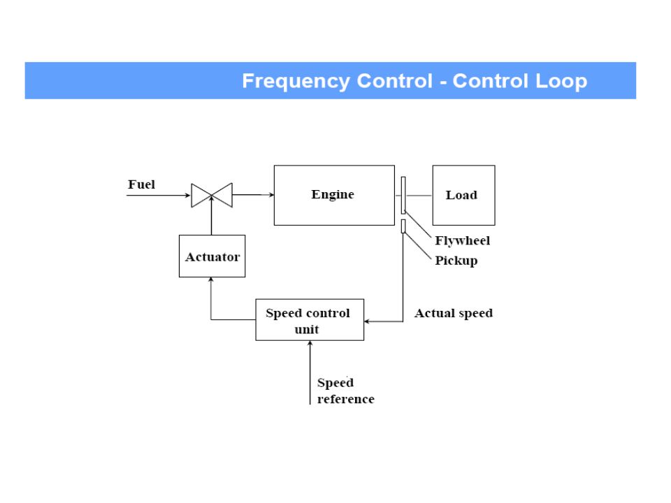
Steam Engine Speed Control
Machine Operator Machine Use Steam Supply Fly-Ball Governor Deviation Negative (Balancing) Feedback Sensor Actuator Controller Feedback Loop Desired Speed Steam Engine Actual Speed
 Feedback. Sensor. Actuator. Controller. Feedback Loop. Desired. Speed. Steam. Engine. Actual Speed.")
23
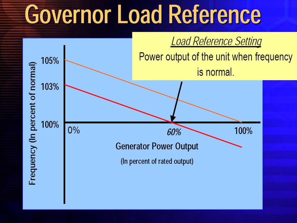
Governors. To provide an equitable and
coordinated system response to load/generation imbalances, governor droop shall be set at 5%. Governors shall not be operated with excessive deadbands, and governors shall not be blocked unless required by regulator mandates

24
Assume that all generators on a power grid are operating in the droop mode with the same 4 percent speed regulation. Assume also that one of the generators is rated at 50 megawatts (call it Unit #1) and is synchronized on a grid whose total generating capacity is 8000 megawatts. The speed governor for Unit #1 will take 50 ÷ 8000 or .625% of any load demand changes that should occur. For example, assume that Unit #1 is currently generating 37 MW. If the grid is operating at Hz and an increase in demand of 5 MW occurs, Unit #1 will increase its power output by: (.00625)(5) = MW. Unit #1 will then be generating MW.
 and is synchronized on a grid whose total generating capacity is 8000 megawatts. The speed governor for Unit #1 will take 50 ÷ 8000 or .625% of any load demand changes that should occur. For example, assume that Unit #1 is currently generating 37 MW. If the grid is operating at Hz and an increase in demand of 5 MW occurs, Unit #1 will increase its power output by: (.00625)(5) = MW. Unit #1 will then be generating MW.")
25
The other generators, with their own 4 % droop characteristic, will share proportionally the remainder of the load change (that is, 5 MW minus = ). In the above example, something happens to grid frequency as well. Assume that the frequency is Hz when the additional load of 5 MW came on the grid. In this example, the system frequency would droop the following amount: [(.04) (60) (5) ÷ 8000] = = Hz If the operator increases the setpoint on Unit #1 as the other governor setpoints remain steady, the frequency will return to Hz and all of the new load of 5 MW will be transferred to Unit #1.
 (60) (5) ÷ 8000] = = Hz. If the operator increases the setpoint on Unit #1 as the other governor setpoints remain steady, the frequency will return to Hz and all of the new load of 5 MW will be transferred to Unit #1.")
26
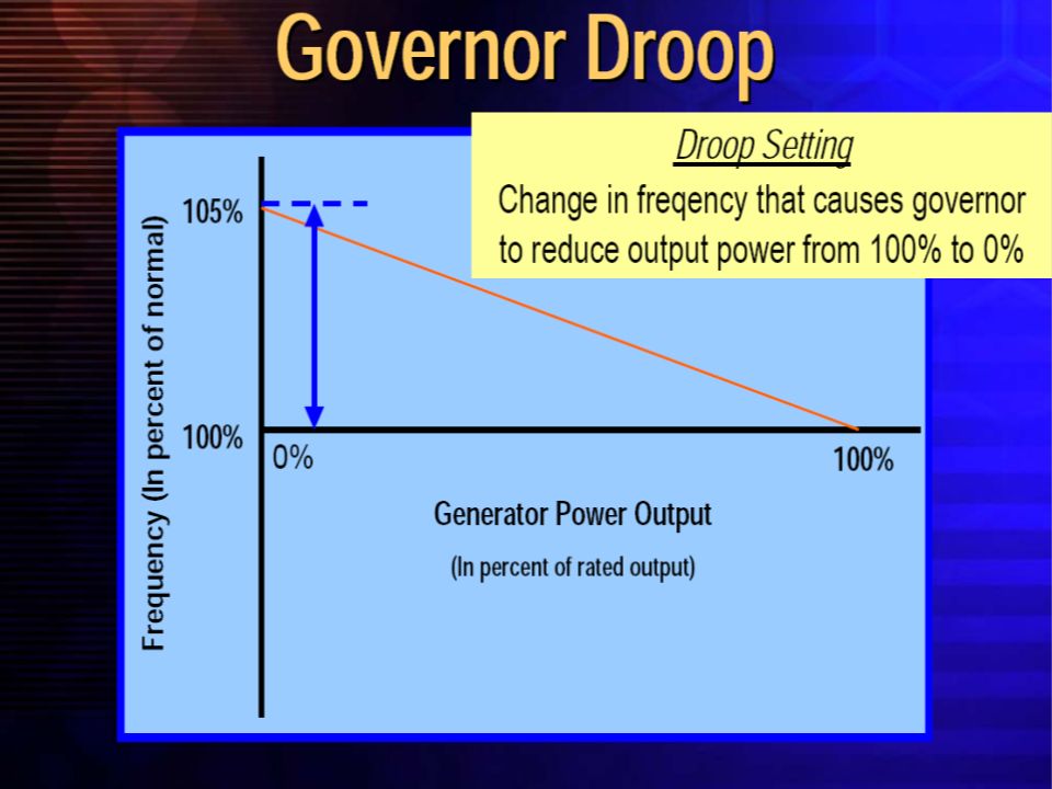
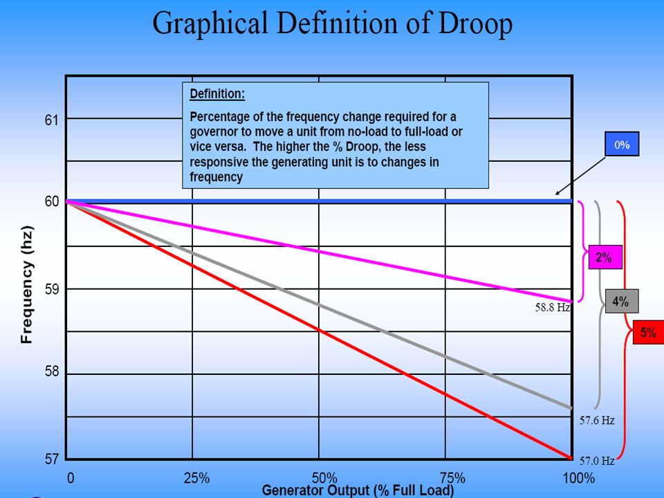
Droop Setting Determines Response
5% Droop: 100% change in generator output for a 5% change in Frequency or Speed. A 5% change in frequency, 60 Hz x 0.05 = 3 Hz or for a 2 pole generator, 3600 rpm x 0.05 = 180 rpm. 4% Droop: 100% change in generator output for a 4% change in Frequency or Speed. A 4% change in frequency, 60 Hz x 0.04 = 2.4 Hz or for a 2 pole generator, 3600 rpm x 0.04 = 144 rpm. 4% Droop setting is more sensitive (responsive) than the 5% Droop setting.
 than the 5% Droop setting.")
27
Example of Expected Response
150 MW unit at 5% Droop 150 / 3 Hz = MW/Hz or in tenths of Hz, 5.00 MW/0.1 Hz Frequency change from to should result in the generator increasing output 5.0 MW’s 150 MW unit at 4% Droop 150 / 2.4 Hz = MW/Hz or in tenths of Hz, 6.25 MW/0.1 Hz Frequency change from to should result in the generator increasing output 6.25 MW’s

28
Expected Governor Response
5 % Droop: Unit Net Capability/30 = MW/0.10 Hz 4 % Droop: Unit Net Capability/24 = MW/0.10 Hz

29
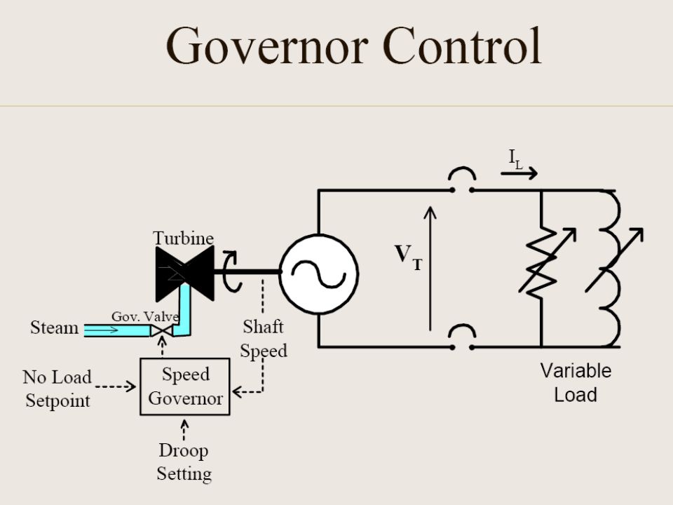
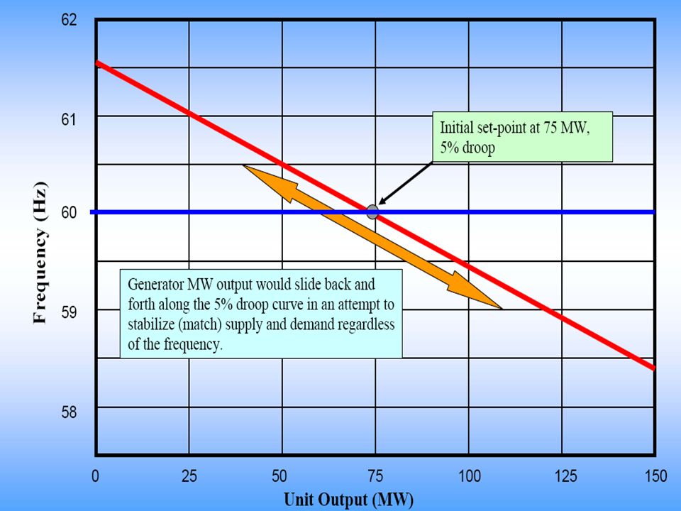
Droop Mode Versus Isochronous Mode
Droop Mode: It is the mode of operation in which the machine will react to the load variation by changing its speed. It is utilized when multiple machine run in parallel so that load is shared between the machines. For this sharing to be equal the machine need to have same droop characteristic. Typically if a machine has droop of 4% it means for a change of 1% in rated speed the machine takes 25% of its rated load. This is also referred to as load control mode of operation. Isochronous Mode: In this mode the machine is not affected by load and regardless of load it will maintain the frequency. This mode is also referred to as frequency control mode of operation. In case of systems not connected to grid it is required to run at least one machine in this mode so as to take care of the load variation.

Similar presentations

>")
>")
>")
 CHAPTER SIX ……SYNCHRONOUS MOTORS.>")


