Download presentation
Presentation is loading. Please wait.

1
Jump to first page 1 Marine Guard Actual Marine Guard 2000 Security System Installation

2
Jump to first page 2 Marine Guard 2000 n Sea-Curity Systems of New York installed a Marine Guard 2000 security system on this 28’ Boston Whaler Conquest. n This particular system was installed in July 2000 because the boat had been vandalized. Picture as seen at Boston Whaler website (www.whaler.com)

3
Jump to first page 3 Entering the Conquest n The first Pulsor is mounted under the rear battery hatch (1). n As you can see, this Pulsor is invisible, but provides early warning if someone steps on the platform. n Hatch contact protecting battery compartment (2). 1 1 2
")
4
Jump to first page 4 Pulsors and Contacts in Cockpit Area n Two Pulsors are located in the cockpit area. One is mounted in the center section of cockpit (1). The other is mounted on the starboard side (2). n Hatch contact protects alarm panel location (3). n Alarm panel mounted under decking (4). 1 2 3 4
. The other is mounted on the starboard side (2). n Hatch contact protects alarm panel location (3). n Alarm panel mounted under decking (4)")
5
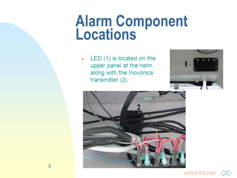
Jump to first page 5 Alarm Component Locations n LED (1) is located on the upper panel at the helm along with the Inovonics transmitter (2). 1 2 1
6
Jump to first page 6 n Alarm siren located inside of starboard gunwale (1). n The annunciation chime (2) and switch plate that enables/disables this feature located on starboard wall in cabin area. Additional Features 1 2 n Two halogen lamps provide automatic lighting during alarm condition. Lighting also is triggered for 1 minute when alarm system is disarmed (no photo).
 and switch plate that enables/disables this feature located on starboard wall in cabin area. Additional Features 1 2 n Two halogen lamps provide automatic lighting during alarm condition. Lighting also is triggered for 1 minute when alarm system is disarmed (no photo)..")
7
Jump to first page 7 How to Install a Boat Alarm System n First, you want to determine the location for alarm control panel. n Next, you need to decide where the Pulsors and all electronic components will be located. n Next you will need to decide how you will run wire and then you will remove whatever paneling is necessary to make wiring runs accessible.

8
Jump to first page 8 How to Install Wire on a Boat (2) n Next you want to lay out the main split tubing on top of the boat. Leave excess tubing. It is easier to cut a wire than it is to extend it. (Colors are for identification purposes.)
.")
9
Jump to first page 9 Next Step: Insert Wires into Tubing n Orange Colored Tubing - Insert the following wires: 1 pair 12-gauge wire for halogen lights, 1 4-conductor, 22-gauge wire for Inovonics transmitter, 1 pair 16- gauge wire for siren, 1 4-conductor, 22-gauge wire for chime plate, 1 pair 22-gauge wire for L.E.D. n Blue Colored Tubing - Insert the following wires: 1 pair 22-gauge wire for L.E.D., 4-conductor, 22-gauge for Inovonics transmitter and 12-gauge wire for halogen lights. n Red Colored Tubing - Insert 1 4-conductor, 22-gauge wire for chime plate. n Pink Colored Tubing - Insert 16-gauge siren wire. n Green Colored Tubing - Insert the 12-gauge wire for battery hook up, 22-gauge wire for hatch contact, and 4 conductor, 22-conductor wire for Pulsor by battery compartment.

10
Jump to first page Run Tubing Throughout Boat n Blue, red and pink tubing from the individual electronic components meet here. They are joined to the orange tubing that then runs all the wires back to the alarm panel. n Upper panel - transmitter, light switch & LED (1) n Lower panel - wire run(2) n Forward cabin - Chime plate (3) n Bathroom cabinet - wire run (4) n Starboard wall - Captain’s chair (5) 1 2 34 5
 n Lower panel - wire run(2) n Forward cabin - Chime plate (3) n Bathroom cabinet - wire run (4) n Starboard wall - Captain’s chair (5)")
11
Jump to first page 11 Run Tubing Throughout Boat (2) n Orange tubing is run from the captain’s chair (front) towards the rear of the boat. Then it is run around and through the battery compartment into the storage area under the cockpit deck where the alarm control panel is located. At the battery compartment, the green tubing is picked up and run simultaneously to the alarm panel.

12
Jump to first page 12 The Invisible Pulsor n After the tubing has been run, you will mount two of the Pulsors (the center (1) and starboard Pulsors in the cockpit area). You will need to make sure you have ample wire attached to the Pulsor so that the wire will reach the alarm panel. You do not want to have to add wire after the Pulsor is mounted. Also mount contact to protect the hatch in cockpit area. Note: Pulsor wires are encased in tubing. 1

13
Jump to first page 13 Mounting Components in Battery Compartment n Mount contact (1), magnet (2) and third Pulsor (3) in battery compartment area. Also install power (4). Note: you must use the appropriate size fuse. The size is determined by the amount of current needed to drive the lights and siren. 1 2 3 4
. Note: you must use the appropriate size fuse. The size is determined by the amount of current needed to drive the lights and siren")
14
Jump to first page 14 Mounting Siren, Chime Plate & Light Control n Mount siren behind starboard gunwale. You may have to drill hidden holes to make the sound from the siren more effective. n Mount chime plate in forward cabin. n Install components in upper panel: Inovonics transmitter*, L.E.D. and lighting controls. The wires for the lighting controls get attached in parallel to the light control switch enabling lights to be triggered by flipping the switch or by disarming the alarm system. * Note: Inovonics transmitter and receiver allows an alarm signal to be sent to a boat owner’s home. Boat needs to be within 4,000 feet of the house.

15
Jump to first page 15 Sorting Wires at Alarm Panel n All wire sorting is done in as comfortable a position as possible. You want to mount the alarm panel after all wires are attached.

16
Jump to first page 16 Mounting the Alarm Control Box & Securing Tubing

17
Jump to first page 17 Marine Guard 2000 n Marine Guard 2000 control panel & NEMA III weather- resistant box n 2 wireless water-resistant transmitters n 4-zone RF receiver n 2 Marine Pulsors (SU-MG2003 expandable to 6 Pulsors) n Chime mounted on an on/off switch plate n One siren
 n Chime mounted on an on/off switch plate n One siren")
18
Jump to first page 18 Optional Components n Inovonics transmitter to enable alarm code to be sent to boat owner’s home. Two transmitters available. Add suffix TXR for 2,000 foot range or TXL for 4,000 foot range. n Service transmitter. Allows service technician to temporarily disarm the security system. n COMING SOON - Ability to send alarm signal to pagers and central station.

Similar presentations


