Download presentation
Presentation is loading. Please wait.

2
Heat engine is defined as a device that converts heat into mechanical energy or more exactly a system which operates continuously and only heat and work may pass across its boundaries. The operation of a heat engine can be best represented by a thermodynamic cycle.

3
A thermodynamic cycle is defined as a process in which a working fluid undergoes a series of state changes and finally returns to its initial state. Some example of a thermodynamic cycles are: Otto cycle Diesel

4
The efficiency of heat engines was first investigated by Carnot in 1824 and expanded upon by Clapeyron who provided analytical tools in 1834 and Kelvin who stated the Second Law of Thermodynamics in 1851 and finally by Clausius who introduced the concept of entropy in 1865.

5
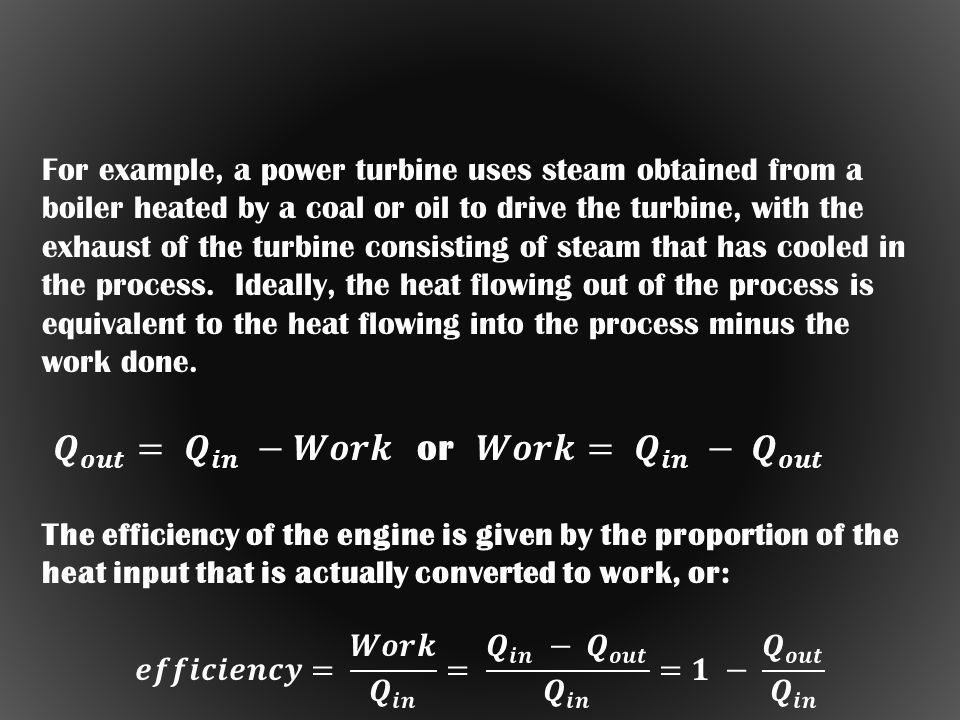
All mechanical engines are "heat engines", in which heat is converted to work. Automotive engines burn fuel to set the vehicle rolling, while jet engines burn fuel to generate thrust to keep the aircraft flying. Such engines obtain heat from a high- temperature reservoir, derive work from it, and then pass the waste heat on to a low- temperature reservoir. The Second Law of Thermodynamics has particular application in the analysis of the operation of heat engines.

6
Schematic diagram of a heat engine

7
In an "ideal" heat engine, all the heat is converted to work. However, the French engineer Nicolas Leonard Sadi Carnot (1796:1832) demonstrated that there is no way to build a 100% efficient heat engine. In a work published in 1824, Carnot showed that the efficiency of an engine is proportional to the temperature difference between the input and output, and to obtain 100% efficiency the difference would have to be infinite.
 demonstrated that there is no way to build a 100% efficient heat engine. In a work published in 1824, Carnot showed that the efficiency of an engine is proportional to the temperature difference between the input and output, and to obtain 100% efficiency the difference would have to be infinite..")
10
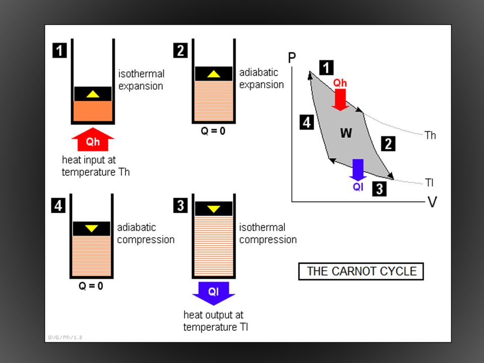
Obviously, the efficiency is maximum when the heat output is zero -- meaning the heat input is completely used up -- but this never happens in practice, and this circumstance can be theoretically shown to be impossible. This is a consequence of the Second Law, though the analysis is too complicated to be presented in this document. Carnot established these basic rules by performing a theoretical analysis of a simple "ideal" heat engine that provides a basis for the discussion of all heat engines. The "Carnot engine", as it is now known, is a simple cylinder plugged by a piston and containing a quantity of gas, or "working fluid".

12
In more detail, the cycle works as follows: [1] Input of heat “Q h ” at high temperature “T h ” results in constant temperature (isothermal) expansion raising the piston. [2] Heat imput is removed, and the gas continues to expand, raising the piston further. Heat does not escape from the system during this phase of the cycle, or in other words this phase is an “adiabatic” process. [3] Loss of heat “Q c ” at a low temperature “T c ” causes the gas to compress in an isothermal fashion. [4] Heat no longer flows out of the cylinder but the gas continues to compress as an adiabatic process. The process then starts over at phase 1.
![In more detail, the cycle works as follows: [1] Input of heat Q h at high temperature T h results in constant temperature (isothermal) expansion raising the piston.](http://images.slideplayer.com/27/9089527/slides/slide_12.jpg "[2] Heat imput is removed, and the gas continues to expand, raising the piston further. Heat does not escape from the system during this phase of the cycle, or in other words this phase is an adiabatic process. [3] Loss of heat Q c at a low temperature T c causes the gas to compress in an isothermal fashion. [4] Heat no longer flows out of the cylinder but the gas continues to compress as an adiabatic process. The process then starts over at phase 1..")
14
OTTO CYCLE - this is an idealization of a set of processes used by spark ignition internal combustion (2-stroke or 4- stroke cycles)
")
16
Operation of the Otto cycle: [1] In the first part of the cycle, the “intake stroke,” the intake valve opens and the piston moves down to its lowest position. This draws in a gasoline-air mixture at (constant) atmospheric pressure. [2] In the “compression stroke”, the intake valve is closed and the piston moves to its top position, compressing the fuel-air mixture. This is done quickly enough so that this part of the cylce is effectively adiabatic.
![Operation of the Otto cycle: [1] In the first part of the cycle, the intake stroke, the intake valve opens and the piston moves down to its lowest position.](http://images.slideplayer.com/27/9089527/slides/slide_16.jpg "This draws in a gasoline-air mixture at (constant) atmospheric pressure. [2] In the compression stroke , the intake valve is closed and the piston moves to its top position, compressing the fuel-air mixture. This is done quickly enough so that this part of the cylce is effectively adiabatic..")
17
[3] In the “power stroke”, an electric spark plug ignites the compressed fuel-air mixture, driving the piston to its lowest position. [ 4] In the “exhaust stroke”, the exhaust valve opens and the piston moves up, exhausting the combustion products of the fuel-air mixture at (constant) atmospheric pressure.
![[3] In the power stroke , an electric spark plug ignites the compressed fuel-air mixture, driving the piston to its lowest position.](http://images.slideplayer.com/27/9089527/slides/slide_17.jpg "[ 4] In the exhaust stroke , the exhaust valve opens and the piston moves up, exhausting the combustion products of the fuel-air mixture at (constant) atmospheric pressure..")
18
PV diagram of an Otto Cycle

20
Analysis of the Otto cycle engine shows that its efficiency is mostly dependent on the "compression ratio", that is, the ratio of maximum compression of the fuel-air mixture to atmospheric pressure. The greater the compression ratio, the more efficient the engine. However, the Otto cycle engine is limited on the level of compression it can obtain, since at high compressions the temperatures and pressures will cause the fuel-air mixture to ignite spontaneously before the piston reaches the top of its travel. This phenomenon is known as "engine knock".

21
Knocking (also called knock, detonation, spark knock, pinging or pinking) in spark-ignition internal combustion engine occurs when combustion of the air/fuel mixture in the cylinder starts off correctly in response to ignition by the spark plug, but one or more pockets of air/fuel mixture explode outside the envelope of the normal combustion front. The fuel-air charge is meant to be ignited by the spark plug only, and at a precise time in the piston's stroke cycle. Knock occurs when the peak of the combustion process no longer occurs at the optimum moment for the four –stroke cycle. The shock wave creates the characteristic metallic "pinging" sound, and cylinder pressure increases dramatically. Effects of engine knocking range from inconsequential to completely destructive.

22
The "Diesel cycle" engine avoids this problem. It has the same general four-stroke operational cycle as the Otto cycle engine, but uses a fuel injection system to spurt fuel directly into the cylinder at the end of the compression stroke, permitting higher compression ratios. The Diesel engine uses heavier fuels than the Otto cycle engine. It does not use spark plugs, instead using "glow plugs" that are heated and assist ignition of the fuel-air mixture when the compression reaches the proper level.

23
A glow plug (alternatively spelled glowplug or glow-plug) is a device, similar to a spark plug, used to help ignite the fuel in the very small internal combustion engine typically used in model aircraft, model cars and similar applications. The ignition is accomplished by a combination of heating from compression, heating from the glow plug and the catalytic effect of the platinum within the glow plug on the methanol within the fuel. The glow plug is a durable, mostly platinum, helical wire filament recessed into the plug's tip. When an electric current runs through the plug, or when exposed to the heat of the combustion chamber, the filament glows, enabling it to help ignite the special fuel used by these engines. Power can be applied using a special connector attaching to the outside of the engine, and may use a rechargeable battery or DC power source.

24
A second variation on the Otto cycle is the "two-stroke" engine, in which the intake and expansion cycles are combined, as are the compression and exhaust cycles. This means that the two-stroke engine has, in the limit, twice as much power for a given RPM than a four-stroke engine and is correspondingly lighter. The problem with two-stroke engines is that they unsurprisingly burn very dirty, and so have been generally banned by air-pollution regulations. However, experimental two-stroke engines have been built that use electronic control systems to meet air-pollution regulations.

25
Components of a Refrigerator

26
1. Compressor -It takes refrigerant vapor in from the low pressure side of the circuit, and discharges it at a much higher pressure into the high pressure side of the circuit -It is the heart of the system; it keeps the refrigerant flowing through the system at specific rates of flow, and at specific pressures -The rate of flow through the system will depend on the refrigerant being used and the desired evaporator temperature

27
Components of a Refrigerator 2. Condenser -The red dots inside the piping represent discharge vapor -The solid red color represents high pressure liquid refrigerant -Most air cooled refrigeration system are designed so that the refrigerant will condense at a temperature about 25 to 30 degrees above the ambient air temperature around the condenser.

Similar presentations


>")

, HOSUR DEPARTMENT OF MECHANICAL ENGINEERING AIR POWERED CAR (COMPRESSED AIR AS AN ALTERNATE FUEL) 123seminarsonly.com.>")


 Stirling heat engine Internal combustion engine (Otto cycle) Diesel engine Steam engine (Rankine.>")


