Download presentation
Presentation is loading. Please wait.

1
CISCO PACKET TRACER By:- Ankita Rawat Sohit Mehta Sukhwinder Singh

2
Introduction: Packet Tracer is a program used to illustrate at a basic level how networks work. It is used to create & simulate network virtually. It gives same environment virtually as it exists physically.

3
HUBS A common connection point for devices in a network.
Works on physical layer of OSI model. Commonly used to connect segments of a LAN and have multiple ports. When a packet arrives at one port, it is copied to the other ports so that all segments of the LAN can see all packets.(Broadcast)
")
4
Switches: Device that filters and forwards packets between LAN segments. Operate at the data link layer. Switch actually checks for the destination MAC address and forward it to the relevant port to reach that computer only. They build a table of which MAC address belongs to which segment.

5
Routers: Bridges: Works on Network Layer of OSI Model
Routers are used to connect different LANs or a LAN with a WAN (e.g. the internet). Routers are located at gateways, the places where two or more networks connect. Bridges: Maintains a MAC address table for both LAN segments it is connected to. Single incoming and outgoing port
. Routers are located at gateways, the places where two or more networks connect. Bridges: Maintains a MAC address table for both LAN segments it is connected to. Single incoming and outgoing port.")
6
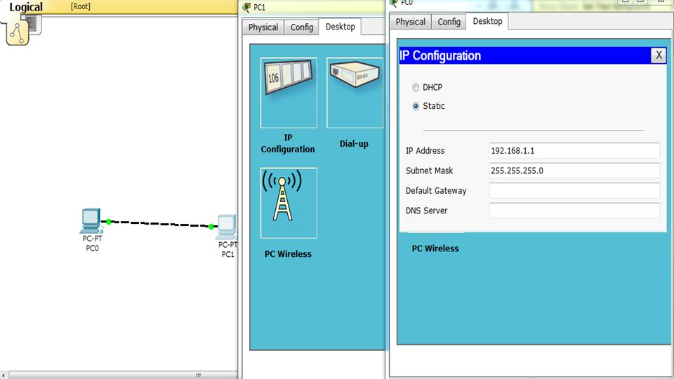
SAMPLE NETWORK SIMULATION
Select the Generic PC under End Devices and drag it as the first PC onto the workspace. To set IP address of PC: Select PC in which you want to set IP Address, Click on it. One menu will open having three tabs: Physical, Config, Desktop. Select Desktop and go to “IP Configuration”. Here you can set IP Addresses.

8
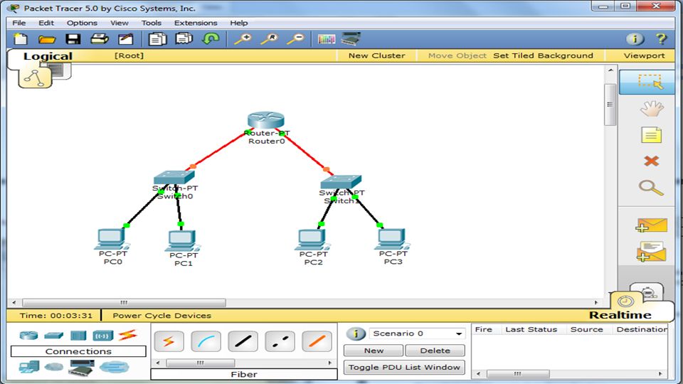
Two network two switch and one router
Step1: Put four PC, One Generic Switch & One Generic Router PC0 & PC1 for Network 1 PC2 & PC3 for Network 2 Step2: Connect them all(Switch & PCs) with copper straight cable Step3: Connect Switches with Router using Fiber Cable
 with copper straight cable. Step3: Connect Switches with Router using Fiber Cable.")
10
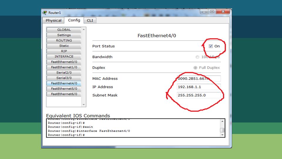
SAMPLE NETWORK SIMULATION
To configure a router: Select Router , click on it. One menu will open having three tabs: Physical, Config, CLI. Select Config. Select Interface in which you want to set IP, i.e.FastEthernet4/0. Set IP Address in it & Check the ON check box. *Network address of each port of router should be of the same network that it is connected to. .

12
Here one port of Switch1 is blocked due to loop formation.

13
Working with wireless router
Wireless router mostly use DHCP servers to config devices. While connecting to wireless router, you need wireless diveces too. In cisco packet tracer, default pc’s don’t have wireless modules. You have to add them as shown in fig.

14
In 1st fig default view is shown
In 1st fig default view is shown. Switch of the power, remove default port, add wireless module an turn the power on.

15
Configuring wireless router.
Remember this router can have both wired and wireless connections.

16
Linksys router with wired and wireless connection.

17
STP:Spanning Tree Protocol The Spanning Tree Protocol (STP) is an older network protocol that ensures a loop-free topology for any bridged Ethernet local area network.. Used Protocols

18
PROTOCOLS:CDP(Cisco Discovery Protocol)
CDP is a data link layer protocol. Routers and catalyst switches support CDP.. CDP messages are not forwarded. It means you can get CDP information only about the directly connected(neighbour) devices.
 devices.")
19
PROTOCOLS: DTP: Cisco’s Dynamic Trunking Protocol can facilitate the automatic creation of trunks between two switches. ARP:(Address Resolution Protocol) ARP maps an IP address to the physical address of host.
 ARP maps an IP address to the physical address of host.")
20
PROTOCOLS: ICMP: (Internet Control Message Protocol)It is a network layer protocol designed to compensate deficiencies like error correcting mechanism and mechanism for host and management queries in IP protocol.
It is a network layer protocol designed to compensate deficiencies like error correcting mechanism and mechanism for host and management queries in IP protocol.")
21
Some important things to remember
Try to not to form any loop with in network. Straight cables are used to connect different layer devices like pc-switch, switch-router etc. Cross cables are used to connect same layer devices like pc-pc, switch-switch. Roll over wire is used to connect console ports. Don’t use first IP (eg ) and last IP (eg ) in any case. You can add available module to any device. As used in pc, similar modules can be added to router to increase its port no’s etc.
 and last IP (eg ) in any case. You can add available module to any device. As used in pc, similar modules can be added to router to increase its port no’s etc.")
22
Thankyou

Similar presentations


. Switches, also known as switching hubs, have become an increasingly important part of our networking today, because when working with hubs,>")


. VLANs provide greater opportunities to manage the flow of traffic on.>")

