Download presentation
Presentation is loading. Please wait.

1
CSE 219 Computer Science III UML

2
UML Diagrams UML - Unified Modeling Language UML diagrams are used to design object-oriented software systems –represent systems visually –provides a system architecture –makes coding more efficient and system more reliable –diagrams show relationships among classes and objects Can software engineering be automated? –Visual programming –Patterns & frameworks –CASE tools

3
Types of UML Diagrams Use Case Diagram - displays the relationship among actors and use cases Class Diagram - models class structure and contents. Also displays relationships such as aggregation, inheritance, etc … Sequence Diagram – shows interaction among constructed objects Others: –State, Activity, Collaboration, Communication, Component, & Deployment Diagrams

4
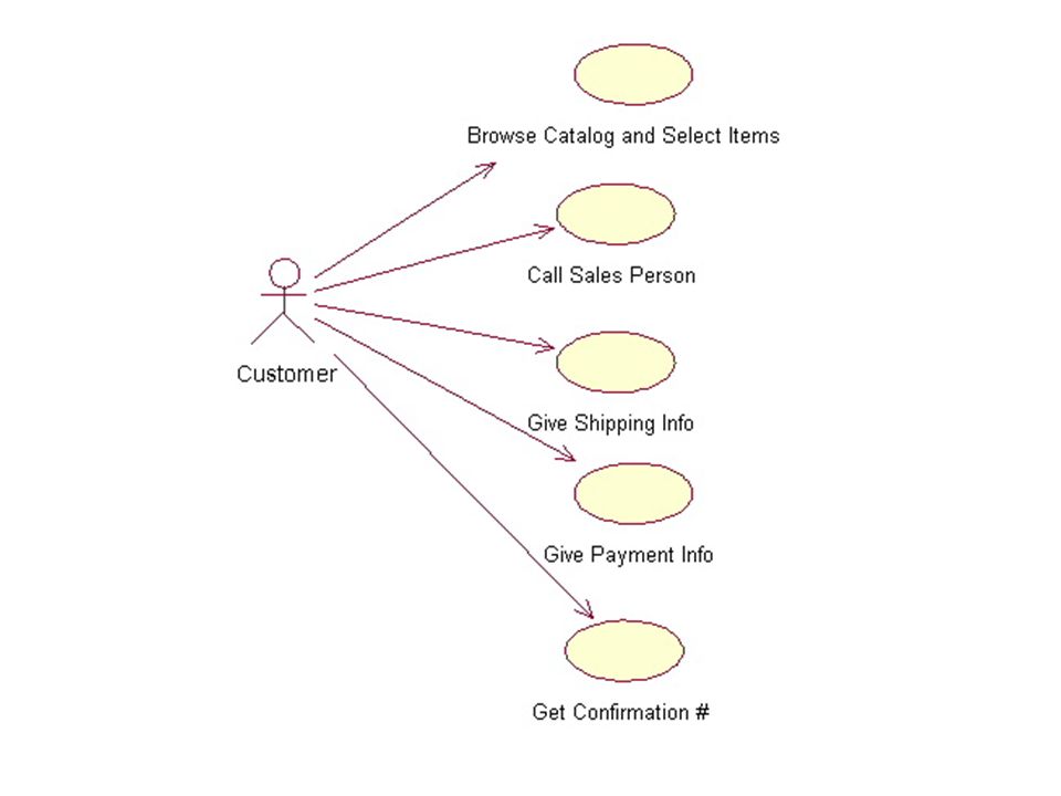
A set of scenarios that describe an interaction between a user and a system UML Use Case Diagrams Done first in a project design –helps you to better understand the system requirements To draw a Use Case Diagram: –List a sequence of steps a user might take in order to complete an action. –Example actor: a user placing an order with a sales company

6
UML Class Diagrams A UML class diagram consists of one or more classes, each with sections for: –class name –instance variables –methods Lines between classes represent associations –Uses –Aggregation (HAS-A), also known as containment –Inheritance (IS-A)
, also known as containment –Inheritance (IS-A)")
7
UML Class Responsibilities Diagrams PairOfDice State Info:die1: Die die2: Die Responsibilities: access instance variables roll dice calculate total Die State Info:number of faces value facing up Responsibilities: access instance variables roll die Class Name Responsibilities to be translated into methods State info to be translated into instance variables

8
UML Class Diagrams Derived from class responsibilities diagrams Show relationships between classes –Class associations denoted by lines connecting classes –A feathered arrow denotes a one-directional association ClassA Instance variable info Method header info ClassB Instance variable info Method header info Feathered arrow means ClassA knows of and uses ClassC, but ClassC has no knowledge of ClassA ClassC Instance variable info Method header info Connecting line means ClassA and ClassB have a relationship

9
Method and Instance Variable Descriptions Instance Variables Format –variableName : variableType –For example, upValue : int Method Header Format –methodName(argumentName : argumentType): returnType –For example, setDie1(newDie1 : Die) : void –$ denotes a static method or variable, for example: $ myStaticMethod(x : int) : void
: returnType –For example, setDie1(newDie1 : Die) : void –$ denotes a static method or variable, for example: $ myStaticMethod(x : int) : void")
10
UML Class Diagrams & Aggregation UML class diagram for PairOfDice & Die: Die numFaces: int upValue : int getUpValue() : int getNumFaces() : int roll() : void PairOfDice die1: Die die2: Die getDie1() : Die getDie2() : Die getTotal() : int rollDice() : void setDie1(newDie1: Die) : void setDie2(newDie2: Die) : void 12 Denote multiplicity, 2 Die object for each PairOfDice object Diamond denotes aggregation PairOfDice HAS-A Die
 : int getNumFaces() : int roll() : void PairOfDice die1: Die die2: Die getDie1() : Die getDie2() : Die getTotal() : int rollDice() : void setDie1(newDie1: Die) : void setDie2(newDie2: Die) : void 12 Denote multiplicity, 2 Die object for each PairOfDice object Diamond denotes aggregation PairOfDice HAS-A Die")
11
UML Class Diagrams & Inheritance public class Student extends Person Person name: String age : int getAge() : int getName() : String setAge(newAge: int) : void Triangle denotes inheritance Student IS-A Person Student gpa: double getGPA() : double setGPA(newGPA: double) : void
 : int getName() : String setAge(newAge: int) : void Triangle denotes inheritance Student IS-A Person Student gpa: double getGPA() : double setGPA(newGPA: double) : void")
12
12 Encapsulation We can take one of two views of an object: –internal - the variables the object holds and the methods that make the object useful –external - the services that an object provides and how the object interacts From the external view, an object is an encapsulated entity, providing a set of specific services These services define the interface to the object –abstraction hides details from the rest of the system

13
Class Diagrams and Encapsulation In a UML class diagram –public members can be preceded by + –private members are preceded by - –protected members are preceded by # Die - numFaces: int - upValue : int + getUpValue() : int + getNumFaces() : int + roll() : void PairOfDice - die1: Die - die2: Die + getDie1() : Die + getDie2() : Die + getTotal() : int + rollDice() : void + setDie1(newDie1: Die) : void + setDie2(newDie2: Die) : void
 : int + getNumFaces() : int + roll() : void PairOfDice - die1: Die - die2: Die + getDie1() : Die + getDie2() : Die + getTotal() : int + rollDice() : void + setDie1(newDie1: Die) : void + setDie2(newDie2: Die) : void")
14
Interfaces in UML (http://www.informit.com/articles/article.asp?p=336264&seqNum=3)http://www.informit.com/articles/article.asp?p=336264&seqNum=3 2 ways to denote an interface 1. >, OR 2. >

15
Abstract Classes in UML (http://www.informit.com/articles/article.asp?p=336264&seqNum=3)http://www.informit.com/articles/article.asp?p=336264&seqNum=3 2 ways to denote a class or method is abstract: 1.class or method name in italics, OR 2.{abstract} notation
 p=336264&seqNum=3 2 ways to denote a class or method is abstract: 1.class or method name in italics, OR 2.{abstract} notation")
16
UML Sequence Diagrams Demonstrate the behavior of objects in program –describe the objects and the messages they pass –diagrams are read left to right and descending

17
UML Sequence Diagrams(Continued) Sequence of messages of a simple Restaurant system. - Patron ordering food and wine - Drinking wine then eating the food, and finally paying for the food.

18
What will we use UML Diagrams for? Class Diagrams –describe all of our classes for our game

Similar presentations


 objectData and operations (functions) are combined >")


