Download presentation
Presentation is loading. Please wait.

1
RFP equilibrium 3

2
The reversed field pinch magnetic equilibrium ORNL Colloquium – September 10th, 2009

3
RFX-RFP configuration RFX coils induction of plasma current RFP configuration toroidal magnetic fieldpoloidal magnetic field mean magnetic field radial profiles

4
European Ph.D. course. - Garching 29.09.08)p.martin Tokamak and RFP profiles
p.martin Tokamak and RFP profiles")
5
European Ph.D. course. - Garching 29.09.08)p.martin safety factor profiles in tok and RFP
p.martin safety factor profiles in tok and RFP")
6
European Ph.D. course. - Garching 29.09.08)p.martin RFP B profile
p.martin RFP B profile")
7
European Ph.D. course. - Garching 29.09.08)p.martin The reversed field pinch Pinch configuration, with low magnetic field The toroidal field is 10 times smaller than in a tokamak with similar current Reactor issues: normal magnets, low force at the coils, high mass power density, no additional heating
p.martin The reversed field pinch Pinch configuration, with low magnetic field The toroidal field is 10 times smaller than in a tokamak with similar current Reactor issues: normal magnets, low force at the coils, high mass power density, no additional heating.")
8
European Ph.D. course. - Garching 29.09.08)p.martin
p.martin")
9
The reversed field pinch Pinch configuration, with low magnetic field B p and B t have comparable amplitude and B t reverses direction at the edge Resonances in RFP : low m (0-2) high n (2*R/a) Safety factor
 high n (2*R/a) Safety factor")
10
European Ph.D. course. - Garching 29.09.08)p.martin The reversed field pinch Pinch configuration, with low magnetic field B p and B t have comparable amplitude and B t reverses direction at the edge Most of the RFP magnetic field is generated by current flowing in the plasma Magnetic self-organization (dynamo)
p.martin The reversed field pinch Pinch configuration, with low magnetic field B p and B t have comparable amplitude and B t reverses direction at the edge Most of the RFP magnetic field is generated by current flowing in the plasma Magnetic self-organization (dynamo).")
11
! RFP dynamo 1 BzBz BB JzJz JJ What we mean with “RFP dynamo effect ” 1/2 Ohm’s law Induction equation stationariety !! inconsistency at reversal

12
RFP dynamo 2 What we mean with “RFP dynamo effect ” : 2/2 to resolve the previous inconsistency we need an “additional” mean electric field with respect to the one provided by mean B and mean v fields, i.e. -within resistive MHD- the contribution by coherent modulation of B and v: E dynamo = E dynamo E dynamo allows us to balance Ohm’s law justifying that in stationary conditions: less mean Jz is driven in the core more mean J is driven in the edge then expected by externally applied E. In other words:

13
About stability and its implication for RFP 4

14
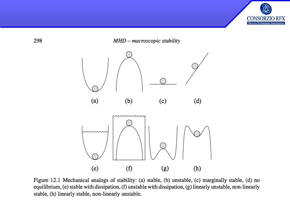
The basic destabilizing forces arise from: –Current density –Pressure gradients, combined with adverse magnetic field curvature The resulting instabilities are divided in two categories –Ideal modes, i.e. instabilities which would occurr even if the plasma were perfectly conducting –Resistive modes, which are dependent on the finite resistivity of the plasma European Ph.D. course. - Garching 29.09.08)p.martin
p.martin.")
19
External Kink mode

20
European Ph.D. course. - Garching 29.09.08)p.martin External Kink mode
p.martin External Kink mode")
21
Current driven kink European Ph.D. course. - Garching 29.09.08)p.martin
p.martin")
22
m=1 kink in tokamak European Ph.D. course. - Garching 29.09.08)p.martin
p.martin")
23
Kruskal Shafranov limit for tokamak

24
European Ph.D. course. - Garching 29.09.08)p.martin q (r) Resistive Wall Modes m=1, n=-7 m=1, n=-8 m=1, n=-9 Resistive Wall Modes m=1, n > 0 m=1, n =-5 m=1, n =-6 m=0, all n Tearing Modes r (m) MHD modes in RFP
p.martin q (r) Resistive Wall Modes m=1, n=-7 m=1, n=-8 m=1, n=-9 Resistive Wall Modes m=1, n > 0 m=1, n =-5 m=1, n =-6 m=0, all n Tearing Modes r (m) MHD modes in RFP.")
25
European Ph.D. course. - Garching 29.09.08)p.martin RFP stability diagram for m=1 modes
p.martin RFP stability diagram for m=1 modes")
26
European Ph.D. course. - Garching 29.09.08)p.martin RFP linear stability
p.martin RFP linear stability")
27
European Ph.D. course. - Garching 29.09.08)p.martin
p.martin")
32
MHD stability: its implication on RFP self-organization and its active control 5

33
Electric field in the RFP The RFP is an ohmically driven system : an inductive toroidal electric field, produced by transformer effect, continuously feeds energy into the plasma Ohm’s law mismatch : the electrical currents flowing in a RFP can not be directly driven by the inductive electric field E o..but stationary ohmic RFP are routinely produced for times longer than the resistive diffusion time overdriven underdriven

34
The RFP dynamo electric field An additional electric field, besides that externally applied, is necessary to sustain and amplify the toroidal magnetic flux. self-organized velocity field in the plasma A Lorentz contribution v x B is necessary, which implies the existence of a self-organized velocity field in the plasma. E dynamo

35
The old paradigm: Multiple Helicity (MH) RFP the safety factor q << 1 and the central peaking of the current density combine to destabilize MHD resistive instabilities. For a long time a broad spectrum of MHD resistive instabilities ( m =0 and m =1, variable n ( “multiple helicity” –MH – spectrum ), was considered a high, but necessary, price to pay for the sustainment of the configuration through the “dynamo” mechanism. br spectrum
, was considered a high, but necessary, price to pay for the sustainment of the configuration through the dynamo mechanism. br spectrum.")
36
Wide k -spectrum bulging in the physical space … severe plasma-wall interaction if the modes lock in phase and to the wall ! A wide spectrum of m=0 and m=1 modes can produce severe plasma-wall interaction if the modes lock in phase and to the wall !

37
At the leading edge of active stability control 192 coils arranged in 48 toroidal positions cover the whole plasma surface Each is independently driven (60 turns, 650 V x 400 A) Digital controller elaborates real-time 576 inputs RFX-mod has the best feedback system for real time control of MHD stability ever realized for a fusion device Full stabilization of multiple RWMs and control of individual tearing modes achieved in RFX-mod and EXTRAP T2-R Demonstrates that a thick stabilizing shell is NOT needed Strong integration between physics and control engineering key for success ORNL Colloquium – September 10th, 2009
 Digital controller elaborates real-time 576 inputs RFX-mod has the best feedback system for real time control of MHD stability ever realized for a fusion device Full stabilization of multiple RWMs and control of individual tearing modes achieved in RFX-mod and EXTRAP T2-R Demonstrates that a thick stabilizing shell is NOT needed Strong integration between physics and control engineering key for success ORNL Colloquium – September 10th, 2009")
38
Feedback Control System Architecture 192 power amplifiers Sensors: b r, b , I coil plasma Each coil independently controlled Digital Controller: 7 computing nodes 2 Gflop/s computing power Cycle frequency = 2.5 kHz cycle latency (≤ 400 s). OUTP UTS: 192 I ref 50 ms thin shell 576 INPUTS: 192b r, 192b , 192I coil b EXT ORNL Colloquium – September 10th, 2009

39
MHD stability feedback control Full stabilization of multiple resistive wall modes in presence of a thin shell (and RWM physics/code benchmarking) Control and tailoring of core resonant tearing modes – mitigation of mode-locking Test of new algorithms and models for feedback control Design of mode controllers RFX PERFORMANCE IMPROVEMENT CONTRIBUTION TO THE GENERAL ISSUE OF MHD STABILITY ACTIVE CONTROL EXPERIMENTAL PROPOSALS FOR 2009 FROM IPP (AUG), DIII-D, JT60-SA ORNL Colloquium – September 10th, 2009
 Control and tailoring of core resonant tearing modes – mitigation of mode-locking Test of new algorithms and models for feedback control Design of mode controllers RFX PERFORMANCE IMPROVEMENT CONTRIBUTION TO THE GENERAL ISSUE OF MHD STABILITY ACTIVE CONTROL EXPERIMENTAL PROPOSALS FOR 2009 FROM IPP (AUG), DIII-D, JT60-SA ORNL Colloquium – September 10th, 2009")
40
Steady progress in performance in a reliable device Fully reliable MHD stability control system no MHD active contro 2004 with MHD active control: 2006 upgraded MHD active control: 2008 spring 2009 - unoptimized ORNL Colloquium – September 10th, 2009

41
Princeton Plasma Physics Laboratory Colloquium - June 4th, 2009 The value of flexibility: high perfomance RFP,… but not only RFP Exploration of high current RFP allows for the discovery of new physics, with structural changes TOKAMAK..but RFX can be run as a 150 kA Tokamak A test bed for MHD feedback control

42
Full control of a (2,1) mode in a ramped tokamak Follows an idea realized in DIII-D on a proposal by In, Okabayashi, et al (with RFX participation) Okabayashi et al., paper EX/P9-5 2008 IAEA FEC, Geneva RED: feedback OFF BLACK: feedback ON (Cavazzana, Marrelli, et al. 2009) ORNL Colloquium – September 10th, 2009
 ORNL Colloquium – September 10th,")
43
Princeton Plasma Physics Laboratory Colloquium - June 4th, 2009 RWM active rotation experiment: setup 2 control time windows: – FIRST: the mode is not controlled – SECOND: the mode is initially feedback controlled with a pure real proportional gain. Gain scan performed (to obtain constant RWM amplitude) The external field is always opposing the plasma error field with the same helicity and no net force is present to induce a controlled rotation. Byproduct: simulation of feedback control systems with not enough power to cope with the growth of the selected instability.
 The external field is always opposing the plasma error field with the same helicity and no net force is present to induce a controlled rotation. Byproduct: simulation of feedback control systems with not enough power to cope with the growth of the selected instability..")
44
Princeton Plasma Physics Laboratory Colloquium - June 4th, 2009 Feedback rotation control principle Perfect control Incomplete control External field Plasma field Total field≠0 External field Plasma field Total field=0

45
Princeton Plasma Physics Laboratory Colloquium - June 4th, 2009 Complex gains (k+ i ) can be used Perfect control Incomplete control External field Plasma field Incomplete control with phase shift Total field≠0 External field Plasma field Total field=0 External field Plasma field Total field≠0
 can be used Perfect control Incomplete control External field Plasma field Incomplete control with phase shift Total field≠0 External field Plasma field Total field=0 External field Plasma field Total field≠0")
46
Princeton Plasma Physics Laboratory Colloquium - June 4th, 20092008 IAEA Fusion Energy Conference, Geneva - P. Martin Advanced RWM control and mode un-locking Active rotation of non-resonant wall-locked RWM is induced by applying complex gains (keeping the mode at the desired constant amplitude) RWM amplitude RWM phase Bolzonella, Igochine et al, PRL 08
 RWM amplitude RWM phase Bolzonella, Igochine et al, PRL 08.")
47
Princeton Plasma Physics Laboratory Colloquium - June 4th, 2009 The old story For a long time it was considered that…. –….a q < 1 configuration like the RFP would have been intrinsically unstable, –with a broad spectrum of MHD resistive instabilities, –causing magnetic chaos and driving anomalous transport. This was viewed as an interesting scientific case but a show- stopper for the RFP reactor ambitions

48
Princeton Plasma Physics Laboratory Colloquium - June 4th, 2009 An emerging view for the RFP For a long time it was considered that…. –….a q < 1 configuration like the RFP would have been intrinsically unstable, –with a broad spectrum of MHD resistive instabilities, –causing magnetic chaos and driving anomalous transport. This was viewed as an interesting scientific case but a show- stopper for the RFP reactor ambitions

49
Princeton Plasma Physics Laboratory Colloquium - June 4th, 2009 Two strategies for chaos-free RFP: 1 Control of the current profile to stabilize tearing modes Proof of principle experiment in MST to test RFP confinement and beta limits at the limit of negligible magnetic fluctuation ( record values E and ) (most recent results in Chapman et al, IAE FEC paper EX/7-1Ra, to appear in NF 2009) Toroidal mode number (~2R/a) amplitude The problem The solution The problem m =1 and m =0 modes Toroidal mode number (~2R/a)
 (most recent results in Chapman et al, IAE FEC paper EX/7-1Ra, to appear in NF 2009) Toroidal mode number (~2R/a) amplitude The problem The solution The problem m =1 and m =0 modes Toroidal mode number (~2R/a)")
50
Dynamo modes active reduction Pulsed Poloidal Current Drive (PPCD): –the induction of a poloidal current at the plasma edge causes a dramatic reduction of the magnetic turbulence and STRONG PLASMA HEATING It is TRANSIENT, but in RFX a quasi-stationary version has been implemented
: –the induction of a poloidal current at the plasma edge causes a dramatic reduction of the magnetic turbulence and STRONG PLASMA HEATING It is TRANSIENT, but in RFX a quasi-stationary version has been implemented")
51
Princeton Plasma Physics Laboratory Colloquium - June 4th, 2009 Density increased, fluctuations still reduced in MST ( =17%) Current drive m = 0 n = 1-4 Ip = 0.5 MA x x x x Tearing amplitudes (G) (m -3 ) Chapman et al., IAEA 2008, tbp in Nucl. Fus.

52
Princeton Plasma Physics Laboratory Colloquium - June 4th, 20092008 IAEA Fusion Energy Conference, Geneva - P. Martin Two strategies for chaos-free RFP: 2 Toroidal mode number (n≈2R/a) amplitude The problem m=1 and m=0 modes Toroidal mode number n=7: the solution Self-organized helical state: at high current the plasma spontaneously chooses a helical equilibrium where only one saturated mode is present, and sustains the configuration This is potentially chaos-free and allows to retain the good features of self-organization without the past degradation of confinement. For Ip > 1 MA this is the preferred state in RFX-mod, with strong electron transport barriers and improved confinement
 amplitude The problem m=1 and m=0 modes Toroidal mode number n=7: the solution Self-organized helical state: at high current the plasma spontaneously chooses a helical equilibrium where only one saturated mode is present, and sustains the configuration This is potentially chaos-free and allows to retain the good features of self-organization without the past degradation of confinement. For Ip > 1 MA this is the preferred state in RFX-mod, with strong electron transport barriers and improved confinement.")
53
Long periods with one large saturated m =1 mode plasma current density Electron temperature BLACK=DOMINANT MODE / color=secondary modes SECONDARY MODES DOMINANT MODE ORNL Colloquium – September 10th, 2009

54
European Ph.D. course. - Garching 29.09.08)p.martin Dynamo electric field is produced in QSH by the dominant mode We are observing the right mechanism! Piovesan et al. PRL 2005 Dynamo electric field toroidal spectrum
p.martin Dynamo electric field is produced in QSH by the dominant mode We are observing the right mechanism. Piovesan et al. PRL 2005 Dynamo electric field toroidal spectrum.")
55
The 1 st bifurcation: from MH to QSH MHQSH Quasi Single Helicity (QSH) states, where the mode n = -7 dominates, and the secondary mode amplitudes are reduced, are observed at medium current (0.5 MA < I p < 1 MA) Escande et al, PRL 2000 Cappello et al., PPCF 46 B313 (2004) A typical feature is the appearance of a thin helical, thermal structure off-axis ORNL Colloquium – September 10th, 2009
 states, where the mode n = -7 dominates, and the secondary mode amplitudes are reduced, are observed at medium current (0.5 MA < I p < 1 MA) Escande et al, PRL 2000 Cappello et al., PPCF 46 B313 (2004) A typical feature is the appearance of a thin helical, thermal structure off-axis ORNL Colloquium – September 10th, 2009")
56
QSH i 2 nd bifurcation at high current: from QSH i to SHAx SHAx single O-point 1 st O-point X-point 2 nd O-point The original axisymmetric axis is replaced by a helical axis as I > 1 MA ORNL Colloquium – September 10th, 2009

57
The drive is mode amplitude: experiment & theory Since the energy of secondary modes is particularly low in SHAx states, it results in a threshold on the ratio dominant/secondary SHAx states appear when the amplitude of the dominant mode exceeds a threshold R. Lorenzini et al., PRL 101, 025005 (2008) ~ 4% of the total B(a) ORNL Colloquium – September 10th, 2009 D. F. Escande et al., PRL. 85, 3169 (2000)
 ~ 4% of the total B(a) ORNL Colloquium – September 10th, 2009 D. F. Escande et al., PRL. 85, 3169 (2000).")
58
Synergistic dependence on Lundquist number S Dominant mode ( m = 1, n = -7) Secondary modes (1,-8 to -15) b/B (%) S S Strongly leading towards chaos-free plasmas At higher current, when plasma gets hotter, the helical state is more pure ORNL Colloquium – September 10th, 2009
 Secondary modes (1,-8 to -15) b/B (%) S S Strongly leading towards chaos-free plasmas At higher current, when plasma gets hotter, the helical state is more pure ORNL Colloquium – September 10th, 2009")
59
RFP helical states 6

60
X point and separatrix Topology change at high current: from island to Single Helical Axis island-like structure predicted physics result strong T gradients …but relatively small volume of plasma involved In 2006: Quasi Single Helicity states where reported: both the helical axis and the original axisymmetric axis were present Te (keV) ORNL Colloquium – September 10th, 2009
 ORNL Colloquium – September 10th, 2009")
61
Single Helical Axis (SHAx) equilibrium at high current The original axisymmetric axis is replaced by a helical magnetic axis thanks to the favourable S-scaling of the modes Strong electron transport barriers 1/L Te ~ 20 m -1 e ~ 10-20 m 2 s -1 Temperature and density are constant on helical magnetic flux surfaces Z (m) Te (keV) ORNL Colloquium – September 10th, 2009
 equilibrium at high current The original axisymmetric axis is replaced by a helical magnetic axis thanks to the favourable S-scaling of the modes Strong electron transport barriers 1/L Te ~ 20 m -1 e ~ m 2 s -1 Temperature and density are constant on helical magnetic flux surfaces Z (m) Te (keV) ORNL Colloquium – September 10th, 2009")
62
Temperature and density are constant on helical magnetic flux surfaces With appropriate reconstruction of the dominant mode eigenfunction, we can build a helical flux (r,u) = m (r,u) - nF(r,u) considering the axisymmetric equilibrium and the dominant mode. (r and u = m -n are flux coordinates). The assumption of good isobaric helical flux surfaces allows mapping of temperature profiles ORNL Colloquium – September 10th, 2009
. The assumption of good isobaric helical flux surfaces allows mapping of temperature profiles ORNL Colloquium – September 10th,")
63
RFP axi-symmetric equilibrium INPUT PARAMETERS: 1/ (s) = 0 circular LCFS (fixed boundary) Total magnetic field Parallel current VMEC adapted for RFP equilibria requires the use of the POLOIDAL FLUX to deal correctly with B reversal. Ongoing work to use VMEC for RFP helical states collaboration with ORNL (S. Hirschmann) and PPPL (Boozer & Pomphreys)
 and PPPL (Boozer & Pomphreys).")
64
RFP Helical equilibrium Parallel current Total magnetic field INPUT PARAMETERS: 1/ (s) = 0 circular LCFS (fixed boundary) Input 1/ profile is obtained by means of the field line tracing code ORBIT.
 = 0 circular LCFS (fixed boundary) Input 1/ profile is obtained by means of the field line tracing code ORBIT.")
65
Flux surfaces The flux surfaces obtained both in axisymmetric and helical configurations provide a good benchmark with present experimental observations and other numerical reconstructions.

66
European Ph.D. course. - Garching 29.09.08)p.martin
p.martin")
67
end

Similar presentations


 Stewart.>")


, M.S.>")


p.martin Piero Martin Consorzio RFX- Associazione Euratom-ENEA sulla fusione, Padova, Italy Department of Physics,>")


, R.Paccagnella.>")

