Download presentation
Presentation is loading. Please wait.

1
Modeling of the set-up for the Project experimental tasks and study of radiation hazard due to lost beam particles in the GSI Future Facilities INTAS-3588 Project Meeting GSI, May 14, 2004 Project Title: Experimental and Theoretical Study of Energy Deposition and Residual Activation Induced by Uranium Ions to Model the Beam Loss Hazards in the GSI Future Facility L.Latysheva, N.Sobolevsky Institute for Nuclear Research of the Russian Academy of Sciences, Moscow E.Mustafin GSI, Darmstadt

2
Contents 1. Sketch of the SHIELD code 2. Examples of simulation SIS100, projectile 238 U, 1 GeV/u 3. Examples of simulation SIS300, projectile 238 U, 37 GeV/u 4. Simulation of experimental set-up for calorimetric measurement of energy deposition 5. Simulation of experimental set-up for residual activation measurement (preliminary results)
.")
3
1.The SHIELD transport code as a tool for simulation of interaction of heavy ion beams with complex extended targets

4
4. Ionization loss, fluctuation of ionization loss and multiple Coulomb scattering of charged hadrons and nuclear fragments. 5. 2- and 3-particle modes of meson decay. 6. Modeling of hA- и AA-interactions in exclusive approach (MSDM-generator). 5 1. Transport of N, , K, N and arbitrary nuclei (A,Z) up to 1 TeV/u. 2. Extended target as a combination of bodies limited by second order.surfaces (CG-compatible) 3. Arbitrary chemical and isotope composition of materials in the target zones. 7. Memorizing of each hadron cascade tree during its simulation without loss of physical information. 8. Storing of sources of , e , e+ and of neutrons (E n <14.5 MeV) during simulation of the hadron cascade.55 9. Neutron transport (E n <14.5 MeV) on the basis of the28-groups ABBN neutron data library. 10. Analog and weighted simulation modes, open architecture of the code Recent version of the SHIELD code
 Transport of N, , K, N and arbitrary nuclei (A,Z) up to 1 TeV/u. 2. Extended target as a combination of bodies limited by second order.surfaces (CG-compatible) 3. Arbitrary chemical and isotope composition of materials in the target zones. 7. Memorizing of each hadron cascade tree during its simulation without loss of physical information. 8. Storing of sources of , e , e+ and of neutrons (E n <14.5 MeV) during simulation of the hadron cascade Neutron transport (E n <14.5 MeV) on the basis of the28-groups ABBN neutron data library. 10. Analog and weighted simulation modes, open architecture of the code Recent version of the SHIELD code.")
5
Modeling of inelastic hA- и AA-interactions (MSDM – Multi Stage Dynamical Model) Fast, cascade stage of nuclear reaction: DCM (Dubna Cascade Model ) [1] Independent Quark-Gluon String Model (QGSM) [2,3] Coalescence model [1] Pre-equilibrium emission of nucleons and lightest nuclei [4] Equilibrium deexitation of residual nucleus: Fermi break up of light nuclei [5] Evaporation/Fission [5,6] Multifragmentation of higly excited nuclei (SMM) [7] 1.V.D.Toneev, K.K.Gudima, Nucl. Phys. A400 (1983) 173c. 2.N.S.Amelin, К.К.Gudima, V.D.Toneev. Yad.Fiz. 51 (1990) 1730 (in Russian). 3.N.S.Amelin, К.К.Gudima, S.Yu.Sivoklokov, V.D.Toneev. Yad.Fiz. 52 (1990) 272 (in Russian). 4.K.K.Gudima, S.G.Mashnik, V.D. Toneev, Nucl. Phys. A401 (1983) 329. 5.A.S.Botvina, A.S.Iljinov, I.N.Mishustin et al., Nucl. Phys. A475 (1987) 663. 6.G.D.Adeev, A.S.Botvina, A.S.Iljinov et al. Preprint INR, 816/93, Moscow, 1993. 7.Botvina, A.S. Iljinov and I.N. Mishustin, Nucl.Phys. A507 (1990) 649. Cross sections of NA-, A- and AA-interactions: V.S.Barashenkov, A.Polanski. Electronic Guide for Nuclear Cross Sections. JINR E2 ‑ 94 ‑ 417, Dubna, 1994. Cross sections of KA- и NA-interactions: B.S.Sychev et al. Report ISTC, Project 187, 1999.
![Modeling of inelastic hA- и AA-interactions (MSDM – Multi Stage Dynamical Model) Fast, cascade stage of nuclear reaction: DCM (Dubna Cascade Model ) [1] Independent Quark-Gluon String Model (QGSM) [2,3] Coalescence model [1] Pre-equilibrium emission of nucleons and lightest nuclei [4] Equilibrium deexitation of residual nucleus: Fermi break up of light nuclei [5] Evaporation/Fission [5,6] Multifragmentation of higly excited nuclei (SMM) [7] 1.V.D.Toneev, K.K.Gudima, Nucl.](http://images.slideplayer.com/27/8959903/slides/slide_5.jpg "Phys. A400 (1983) 173c. 2.N.S.Amelin, К.К.Gudima, V.D.Toneev. Yad.Fiz. 51 (1990) 1730 (in Russian). 3.N.S.Amelin, К.К.Gudima, S.Yu.Sivoklokov, V.D.Toneev. Yad.Fiz. 52 (1990) 272 (in Russian). 4.K.K.Gudima, S.G.Mashnik, V.D. Toneev, Nucl. Phys. A401 (1983) A.S.Botvina, A.S.Iljinov, I.N.Mishustin et al., Nucl. Phys. A475 (1987) G.D.Adeev, A.S.Botvina, A.S.Iljinov et al. Preprint INR, 816/93, Moscow, Botvina, A.S. Iljinov and I.N. Mishustin, Nucl.Phys. A507 (1990) 649. Cross sections of NA-, A- and AA-interactions: V.S.Barashenkov, A.Polanski. Electronic Guide for Nuclear Cross Sections. JINR E2 ‑ 94 ‑ 417, Dubna, Cross sections of KA- и NA-interactions: B.S.Sychev et al. Report ISTC, Project 187,")
6
Neutron yield from lead target. Projectiles: 1 H, 2 H, 4 He and 12 C. Comparison with experiment Neutron yield from Fe and Pb targets. Projectiles from 1 H up to 238 U. SHIELD calculation. Experiment: Vassil’kov, Yurevich ICANS-11, 1990. 12 C 4 He 2H2H Proton Total neutron yield from extended targets under irradiation by heavy ions Pb-target 20 60 cm Fe и Pb-targets 20 60 cm 1 H, 2 H, 4 He, 7 Li, 9 Be, 12 C, 20 Ne, 28 Si, 40 Ca, 56 Fe, 84 Kr, 102 Ru, 140 Ce, 181 Ta, 208 Pb, 238 U Projectiles, 1 и 3.65 GeV/u

7
Differential neutron yield from 3 cm in thick lead target under irradiation by 400 MeV/u 20 Ne ions. Total yield into forward hemisphere (E n >5 MeV): Y exp =5.0(14%), Y calc =5.28 n/proj. Experiment: T.Kurosawa et al. J. Nucl. Sci. Tech. 36 (1999) 41.
: Y exp =5.0(14%), Y calc =5.28 n/proj. Experiment: T.Kurosawa et al. J. Nucl. Sci. Tech. 36 (1999) 41..")
8
Differential neutron yield from iron target (10 10 20 см) under irradiation by 1 GeV/u 238 U ion beam
 under irradiation by 1 GeV/u 238 U ion beam")
9
SHIELDLAHET Target667670 Blanket (total) Rod №1 Rod №2 Rod №13 Rod №14 583 26.9 30.8 10.9 14.6 607 28.1 33.0 11.0 14.6 Whole assembly12501280 Integral energy deposition (MeV/proton) Energy deposition into lead-uranium assembly under irradiation by 1.5 GeV proton beam (The Project «Energy+Transmutation») Target – lead cylinder, size 8.87см 50см, mass 35 кг Blanket – 30 rods 3.6см 20.8см, Nat U in aluminum envelop 0.5 mm, mass 103 кг. Proton energy 1.5 ГэВ

10
2.An example of simulation of energy deposition and neutron fluence in superconducting cables for the SIS100 Dipoles

11
Beam 2 m 2.6 m Irradiation 238 U beam: E U =0.1 or 1 GeV/u Angular divergence of the beam: 1 degree in the XZ-plane for - Entry points for 238 U ions are distributed uniformly over the length of the vacuum tube [0, 4.6 m]. Coordinates (X,Y) of the entry point are distributed uniformly on azimuth angle . Elliptic Vacuum tube Iron tanks, 35 cm, wall thickness 5 mm Geometry of simulation for s. c. cables. General view. Yoke A A Y Z
![Beam 2 m 2.6 m Irradiation 238 U beam: E U =0.1 or 1 GeV/u Angular divergence of the beam: 1 degree in the XZ-plane for - Entry points for 238 U ions are distributed uniformly over the length of the vacuum tube [0, 4.6 m].](http://images.slideplayer.com/27/8959903/slides/slide_11.jpg "Coordinates (X,Y) of the entry point are distributed uniformly on azimuth angle . Elliptic Vacuum tube Iron tanks, 35 cm, wall thickness 5 mm Geometry of simulation for s. c. cables. General view. Yoke A A Y Z.")
12
X Y Geometry of simulation for s. c. cables Cross section on A - A Closest supporting band 1.5 mm in thick Closest cable Distant cable Distant supporting band 1.5 mm in thick Protecting plate Protecting plate Protecting plate 0.0; 0.5; 1.0; 2.0 mm

13
Geometry of simulation for s. c. cables in more details

14
Geometry of simulation for s. c. cables Radial-longitudial partition of the cable 260 cm 1 2 3 4 5 6 7 8 9 10 Position No. 26 cm Zone (L=26 cm)Volume, cm 3 Mass, g Helium3.2670.229 Cooling tube1.83815.805 Epoxy0.4170.625 S.C. wires1.83010.978 NiCr bandage1.0138.508 Kapton0.8571.200 Fiberglass1.1302.148 Total 7x10=70 zones for each cable
Volume, cm 3 Mass, g Helium Cooling tube Epoxy S.C. wires NiCr bandage Kapton Fiberglass Total 7x10=70 zones for each cable.")
17
238 U beam – Closest cable – Energy deposition [GeV/g]
![238 U beam – Closest cable – Energy deposition [GeV/g]](http://images.slideplayer.com/27/8959903/slides/slide_17.jpg "238 U beam – Closest cable – Energy deposition [GeV/g]")
18
With 2 mm protecting Fe strip

19
238 U beam – Closest cable – Neutron fluence [n/cm 2 ]
![238 U beam – Closest cable – Neutron fluence [n/cm 2 ]](http://images.slideplayer.com/27/8959903/slides/slide_19.jpg "238 U beam – Closest cable – Neutron fluence [n/cm 2 ]")
20
3.Some preliminary results for the SIS300 Dipoles at 37 GeV/u 238 U ion beam energy

21
17.92 0.5 0.50.5 0.50.5 29.0 318.0 3.5 10.0 7.07 260.0 3.0 4.174.45 4.95 5.03 6.11 6.19 7.28 10.42 24.22 34.0 0.5 35.2 95.5 12 The vertical longitudinal cross section of superconducting dipole Coil 1 Coil 2 Yoke Collar 1 Subdivision of the coils along Z-axis in 10 parts A - A X Z Diode#3 Diode#1 Diode#2

22
Yoke Collar 1 Cells insertions Coil 1 Coil 2 Insulation 1 Insulation 2 Insulation 3 He 1 He 2 4.17 4.45 24.22 35.2 Cross section B - B Envelope of magnet Collar 2 Collar 3 Cells Insulatons 1,2 Heat insulation layer 4.945 34.0 X Y

27
Diode numberTotal neutron flux, n/(cm 2 projectile) Diode 1 0.103 0.004 Diode 2 0.225 0.007 Diode 3 0.275 0.009 Total neutron flux onto protection diodes of the SYS300 magnets under irradiation by 37 GeV/u 238 U ion beam.
 Diode Diode Diode Total neutron flux onto protection diodes of the SYS300 magnets under irradiation by 37 GeV/u 238 U ion beam.")
28
4.Simulation of experimental set-up for calorimetric measurement of energy deposition in the copper and iron targets

29
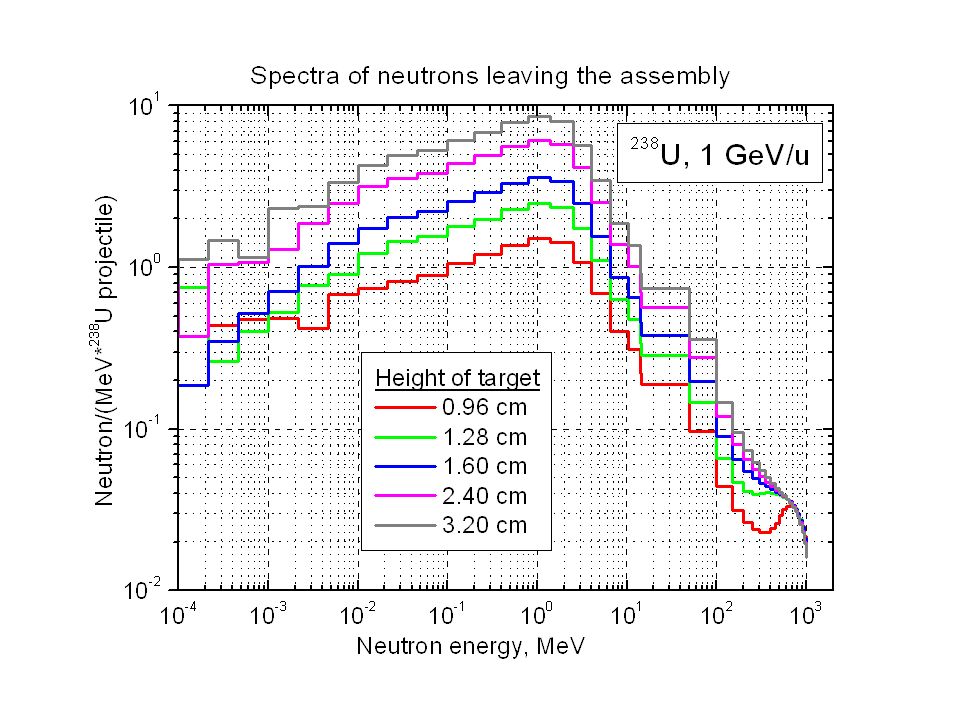
238 U Beam, 1 GeV/u =0.25 cm Cu R=1.0cm H i H 1 =0.3L=0.48 cm H 2 =0.6L=0.96 cm H 3 =0.8L=1.28 cm H 4 =1.0L=1.60 cm H 5 =1.5L=2.40 cm H 6 =2.0L=3.20 cm Cylindrical target Calorimeter: Cu Thickness 100 R=2.5 cm R=0.25 cm Target height, H i 5mm Stop length L=1.6 cm for 238 U ion of 1 GeV/u

31
Balance of energy for Cu-target 2.0 3.2 cm. 238 U, 1 GeV/u (contribution of energy into the assembly is 238 GeV per projectile) Leakage of energy (GeV): n<14.5 MeV0.15 n>14.5 MeV20.0 p9.0 1.1 others0.12 dE/dx200.8 0 2 0.6 SUM231.8
 Leakage of energy (GeV): n<14.5 MeV0.15 n>14.5 MeV20.0 p9.0 1.1 others0.12 dE/dx200.8 0 2 0.6 SUM")
33
5.Simulation of experimental set-up for residual activation measurement in the copper and iron targets (preliminary results)
")
34
238 U Beam 0.2, 0.5, 1 GeV/u Cu Cylindrical target, R=2.0 cm H 2L E, GeV/uH, cm 0.20.25 0.51.1 1.03.0

Similar presentations


 : How to stop , , -rays and neutrons? Multi-Purpose Particle and Heavy Ion Transport code System title1 Feb. 2014 revised.>")


, M.Magistris (1,2), Th.Otto (2), M.Silari (2) (1) Politecnico di Milano; (2) CERN.>")

 especially suitable for deep-sited tumors (brain, neck.>")


 Reactors 2) Usage of reactions 3) Spallation sources Neutron show: 1) Where atoms are (structure)>")


 Aleksander Polanski Joint Institute for Nuclear Research, Dubna, Russia. The Andrzej Soltan Institute for.>")
