Download presentation
Presentation is loading. Please wait.

1
Data and Computer Communications Eighth Edition by William Stallings Lecture slides by Lawrie Brown Chapter 6 – Digital Data Communications Techniques

2
Digital Data Communications Techniques A conversation forms a two-way communication link; there is a measure of symmetry between the two parties, and messages pass to and fro. There is a continual stimulus-response, cyclic action; remarks call up other remarks, and the behavior of the two individuals becomes concerted, co-operative, and directed toward some goal. This is true communication. —On Human Communication, Colin Cherry

3
Transmission Modes data transmission to data communications. Timing problems require a mechanism to synchronize the transmitter and receiver Timing of bits is the key! —Rate —Duration —Spacing ……101101 System A System B

4
Asynchronous and Synchronous Transmission timing problems require a mechanism to synchronize the transmitter and receiver —receiver samples stream at bit intervals —if clocks not aligned and drifting will sample at wrong time after sufficient bits are sent two solutions to synchronizing clocks —asynchronous transmission —synchronous transmission

5
Asynchronous and Synchronous Transmission Assume 1 Mbps data rate Bit time is 1 us (sender’s clock) Assume a drift between Tx clock and Rx clock is 1% (Rx is faster than tx) Bits must be sampled at center First bit will have a drift by 0.01 us After 50 bit the receiver will detect error sample
 Assume a drift between Tx clock and Rx clock is 1% (Rx is faster than tx) Bits must be sampled at center First bit will have a drift by 0.01 us After 50 bit the receiver will detect error sample")
6
Asynchronous and Synchronous Transmission Asynchronous –Each character of data is treated independently Synchronous –For sending large blocks of data –Control schemes Character-oriented Bit-oriented

7
Asynchronous Data transmitted one character at a time —5 to 8 bits Timing only needs to be maintained within each character —TxClk and RxClk need not be in Sync! Resync at the beginning of each character

8
Asynchronous (diagram)
")
9
Example

10
Asynchronous - Behavior In a steady stream, interval between characters is uniform (length of stop element) In idle state, receiver looks for transition 1 to 0 Then samples next seven intervals (char length) Then looks for next 1 to 0 for next char Simple Cheap Overhead of 2 or 3 bits per char (~20%) Good for data with large gaps (keyboard)
 In idle state, receiver looks for transition 1 to 0 Then samples next seven intervals (char length) Then looks for next 1 to 0 for next char Simple Cheap Overhead of 2 or 3 bits per char (~20%) Good for data with large gaps (keyboard)")
11
Synchronous - Bit Level Block of data transmitted without start or stop bits Clocks must be synchronized Can use separate clock line —Good over short distances —Subject to impairments Embed clock signal in data —Manchester encoding —Carrier frequency (analog)
")
12
Synchronous - Block Level another level of synchronization is required Need to indicate start and end of block Use preamble and postamble —e.g. series of SYN (hex 16) characters —e.g. block of 11111111 patterns ending in 11111110 More efficient (lower overhead) than async
 characters —e.g. block of patterns ending in More efficient (lower overhead) than async.")
13
Synchronous (diagram)
")
14
Types of Error All communication channels suffer from noise and signal distortion that cause transmission error An error occurs when a bit is altered between transmission and reception Single bit errors —One bit altered —Adjacent bits not affected —White noise

15
Types of Error Burst errors —A group of bits in which two successive erroneous bits are always separated by less than a given number x of correct bits. The last erroneous bit in the burst and the first erroneous bit in the following burst are accordingly separated by x correct bits or more. —A burst error means that 2 or more bits in the data unit have changed The length is measured from the first corrupted bit to the last corrupted bit —Impulse noise —Fading in wireless —Effect greater at higher data rates

16
Bit and Burst Error

17
Transmission Errors The Bit Error Rate (BER) is a measure of how frequently an error is likely to occur. For example BER of 10 -5 means that. On average, 1 bit in every 100,000 will be wrong. Probabilities with respect to errors in transmitted frame: —P b : Probability that a bit is received in error (BER) —P 1 : probability that a frame arrives with no bit errors. —P 2 : probability that, with an error-detection algorithm in use, a frame arrives with one or more undetected errors —P 3 : probability that, with an error-detection algorithm in use, a frame arrives with one or more detected errors but no undetected bit errors.
 —P 1 : probability that a frame arrives with no bit errors. —P 2 : probability that, with an error-detection algorithm in use, a frame arrives with one or more undetected errors —P 3 : probability that, with an error-detection algorithm in use, a frame arrives with one or more detected errors but no undetected bit errors..")
18
Transmission Errors P 1 = (1 – P b ) F P 2 = ( 1- P 1 ) F is the number of bits per frame
 F P 2 = ( 1- P 1 ) F is the number of bits per frame")
19
Error Detection Process

20
Simple Parity-Check Codes Simplest method and most common method for detecting errors in character oriented transmission. An extra parity bit is added to each character before it is transmitted. The value of the parity is determined by adding up the number ‘1’ bits in the message to be sent. The parity bit is chosen so that the total number of 1 bits, including the parity itself, is either odd or even A simple parity-check code is a single-bit error-detecting code in which n = k + 1 A simple parity-check code can detect an odd number of errors.

21
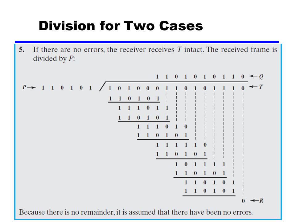
Cyclic Redundancy Check one of most common and powerful checks for block of k bits transmitter generates an n-k bit frame check sequence (FCS) Transmits n bits which is exactly divisible by some number receiver divides frame by that number —if no remainder, assume no error
 Transmits n bits which is exactly divisible by some number receiver divides frame by that number —if no remainder, assume no error")
22
Modular Arithmetic In modulo-N arithmetic, we use only the integers in the range 0 to N −1, inclusive. Modulo 2 arithmetic uses binary addition with no carries Modulo-2 Arithmetic —N is 2 —Use 0 and 1 —Implemented as XOR

23
Cyclic Redundancy Check Define — T = n-bit frame to be transmitted — D = k-bit block of data, or message, the first k bits of T — F = (n-k) – bit FCS, the last (n-k) bits of T — P = pattern of n-k +1 bits, this is the predetermined divisor We want T/P to be with no remainder
 – bit FCS, the last (n-k) bits of T — P = pattern of n-k +1 bits, this is the predetermined divisor We want T/P to be with no remainder")
24
Cyclic Redundancy Check Prepare the transmitted frame —T = 2 n-k D + Fshift by n-k, then add F We want to find F which is the remainder at the TX side. —2 n-k D/P = Q + R/P Because division is modulo 2, the remainder is always at least one bit shorter than the divisor use it as our FCS —T = 2 n-k D + R Does this R satisfy our condition that T/P have no remainder

25
Cyclic Redundancy Check At the receiver —T/P = (2 n-k D + R)/p = 2 n-k D/P + R/P Substitute —T/P = Q + R/P + R/P —T/P = Q+(R+R)/P = Q
/p = 2 n-k D/P + R/P Substitute —T/P = Q + R/P + R/P —T/P = Q+(R+R)/P = Q")
26
Division for Two Cases

28
Cyclic Code Analysis the errors in an n-bit frame can be represented by an n-bit field with 1s in each error position The resulting frame can be expressed as

29
Polynomials

30
The CRC process can now be described as Prove the same result as moduls-2 at the receiver

31
Example

32
Cyclic Code Analysis An error E(X) will only be undetectable if it is divisible by P(X) the following errors are not divisible by a suitably chosen P(X) and hence are detectable:
 will only be undetectable if it is divisible by P(X) the following errors are not divisible by a suitably chosen P(X) and hence are detectable:")
33
Cyclic Code Analysis Consider all error patterns are equally likely r is the length of the FCS For a burst error of length r+1 —the probability of an undetected error (E(X) is divisible by P(X)) is 1/2 r-1 For longer burst, the probability is 1/2 r
 is divisible by P(X)) is 1/2 r-1 For longer burst, the probability is 1/2 r")
34
CRC Standards CRC-12 (X 12 + X 11 + X 3 + X 2 + X + 1) —Used when character length is 6 bits CRC-16 and CRC-CCITT —Used when character length is 8 bits —Used in WANs CRC-32 —Used in LANs
 —Used when character length is 6 bits CRC-16 and CRC-CCITT —Used when character length is 8 bits —Used in WANs CRC-32 —Used in LANs")
35
Digital logic The register contains n-k bits, equal to the length of the FCS There are up to n-k XOR gates The presence or absence of a gate corresponds to the presence or absence of a term in the divisor polynomial, P(X). Excluding the term 1 and X n-k

36
36 Division in CRC Encoder

37
37 Hardware Implementation The divisor is repeatedly XORed with part of the dividend The divisor has n-k+1 bits which either are predefined or all 0s n-k bits of the divisor is needed in the XOR operation. The leftmost bit is always 0

38
Remainder

39
Digital Logic

41
Error Correction Correction of detected errors usually requires data block to be retransmitted (see chapter 7) Not appropriate for wireless applications —Bit error rate is high Lots of retransmissions —Propagation delay can be long (satellite) compared with frame transmission time Would result in retransmission of frame in error plus many subsequent frames Need to correct errors on basis of bits received
 Not appropriate for wireless applications —Bit error rate is high Lots of retransmissions —Propagation delay can be long (satellite) compared with frame transmission time Would result in retransmission of frame in error plus many subsequent frames Need to correct errors on basis of bits received")
42
Error Correction Process Diagram

43
Error Correction Process Each k bit block mapped to an n bit block (n>k) —Codeword —Forward error correction (FEC) encoder Codeword sent Received bit string similar to transmitted but may contain errors Received code word passed to FEC decoder —If no errors, original data block output —Some error patterns can be detected and corrected —Some error patterns can be detected but not corrected —Some (rare) error patterns are not detected Results in incorrect data output from FEC
 —Codeword —Forward error correction (FEC) encoder Codeword sent Received bit string similar to transmitted but may contain errors Received code word passed to FEC decoder —If no errors, original data block output —Some error patterns can be detected and corrected —Some error patterns can be detected but not corrected —Some (rare) error patterns are not detected Results in incorrect data output from FEC")
44
Working of Error Correction Add redundancy to transmitted message Can deduce original in face of certain level of error rate E.g. block error correction code —In general, add (n – k ) bits to end of block Gives n bit block (codeword) All of original k bits included in codeword —Some FEC map k bit input onto n bit codeword such that original k bits do not appear
 bits to end of block Gives n bit block (codeword) All of original k bits included in codeword —Some FEC map k bit input onto n bit codeword such that original k bits do not appear.")
45
Block Code Principle An (n, k) block code encodes k data bits into n-bit codewords Hamming Distance The Hamming distance between any pair of codewords is the number of bit positions at which they differ. the Hamming distance between codewords [1010001] and [1000110] is 4. For a code w 1, w 2, …, w s, s = 2 k, the minimum distance d min of the code is defined as

46
Block Code Principle example For k = 2 and n =5 the following assignment can be made. 00000000100111 10110011111110 The received bit pattern is 00100 The hamming distance d(00000, 00100) = 1;d(00111, 00100) = 2 d(11001, 00100) = 4;d(11110, 00100) = 3 -There are 32 possible codeword of which only 4 are valid. -If the received code is 01010 or 01011 the valid codes are 00000 or 11110 for the first one and 00111 or 11001 for the second.
 = 1;d(00111, 00100) = 2 d(11001, 00100) = 4;d(11110, 00100) = 3 -There are 32 possible codeword of which only 4 are valid. -If the received code is or the valid codes are or for the first one and or for the second..")
47
Block Code Principle The maximum number of guaranteed correctable errors per codeword satisfies Largest integer not exceeds the specified value e.g. 6.3 = 6 The number of errors to be detected satisfies

48
Block Code Principle The design of block codes involves a number of consideration: — For a given value of n and k, we would like the largest possible value of d min — The code should be relatively easy to encode and decode, requiring min. memory and processing time. — We would like the number of extra bits (n-k), to be small, to reduce the bandwidth. — We would like the number of extra bits (n-k), to be large, to reduce error rate.
, to be small, to reduce the bandwidth. — We would like the number of extra bits (n-k), to be large, to reduce error rate..")
49
Block Code Principle coding can be used to reduce the required E b /N 0 value to achieve a given bit error rate (ch 5) The coding discussed in this chapter also has an effect on E b /N 0 the shaded region represents the area in which improvement can be achieved coding gain —the required E b /N 0 to achieve a specified BER of an error-correcting coded system compared to an uncoded system using the same modulation
 The coding discussed in this chapter also has an effect on E b /N 0 the shaded region represents the area in which improvement can be achieved coding gain —the required E b /N 0 to achieve a specified BER of an error-correcting coded system compared to an uncoded system using the same modulation")
50
How Coding Improves System Performance equal number of data and check bits

51
Line Configuration - Topology physical arrangement of stations on medium —point to point - two stations such as between two routers / computers —multi point - multiple stations traditionally mainframe computer and terminals now typically a local area network (LAN)
")
52
Line Configuration - Topology

53
Line Configuration - Duplex classify data exchange as half or full duplex half duplex (two-way alternate) —only one station may transmit at a time —requires one data path full duplex (two-way simultaneous) —simultaneous transmission and reception between two stations —requires two data paths separate media or frequencies used for each direction —or echo canceling a signal processing technique to transmit digital signals simultaneously in both directions on a single transmission line
 —only one station may transmit at a time —requires one data path full duplex (two-way simultaneous) —simultaneous transmission and reception between two stations —requires two data paths separate media or frequencies used for each direction —or echo canceling a signal processing technique to transmit digital signals simultaneously in both directions on a single transmission line")
54
Problem Assignments Solve all the review questions Try the following problems: 6.1, 6.5, 6.10, 6.14, 6.15, 6.17

Similar presentations


 Dr. Marwan Abu-Amara Chapter 6: Digital Data Communications Techniques.>")


 Dr. Marwan Abu-Amara Chapter 6: Digital Data Communications Techniques.>")
 Error Control.>")


