Download presentation
Presentation is loading. Please wait.

1
AE 630 Aero Engineering Thermodynamics

2
Unit - I

3
Thermodynamic Systems, States and Processes
Objectives are to: define thermodynamics systems and states of systems explain how processes affect such systems apply the above thermodynamic terms and ideas to the laws of thermodynamics

4
At room temperature, for most gases:
Internal Energy of a Classical ideal gas “Classical” means Equipartition Principle applies: each molecule has average energy ½ kT per in thermal equilibrium. At room temperature, for most gases: monatomic gas (He, Ne, Ar, …) 3 translational modes (x, y, z) diatomic molecules (N2, O2, CO, …) 3 translational modes (x, y, z) + 2 rotational modes (wx, wy) Note: At higher temps, other modes can come in, e.g., vibrational modes.
 3 translational modes (x, y, z) diatomic molecules (N2, O2, CO, …) 3 translational modes (x, y, z) + 2 rotational modes (wx, wy) Note: At higher temps, other modes can come in, e.g., vibrational modes.")
5
Internal Energy of a Gas
A pressurized gas bottle (V = 0.05 m3), contains helium gas (an ideal monatomic gas) at a pressure p = 1×10⁷ Pa and temperature T = 300 K. What is the internal thermal energy of this gas?
, contains helium gas (an ideal monatomic gas) at a pressure p = 1×10⁷ Pa and temperature T = 300 K. What is the internal thermal energy of this gas")
6
Changing the Internal Energy
U is a “state” function --- depends uniquely on the state of the system in terms of p, V, T etc. (e.g. For a classical ideal gas, U = NkT ) There are two ways to change the internal energy of a system: WORK done by the system on the environment Wby = -Won HEAT is the transfer of thermal energy into the system from the surroundings Q Thermal reservoir Work and Heat are process energies, not state functions.
 There are two ways to change the internal energy of a system: WORK done by the system on the environment. Wby = -Won. HEAT is the transfer of thermal energy into the system from the surroundings. Q. Thermal reservoir. Work and Heat are process energies, not state functions.")
7
Work Done by An Expanding Gas
The expands slowly enough to maintain thermodynamic equilibrium. Increase in volume, dV +dV Positive Work (Work is done by the gas) -dV Negative Work (Work is done on the gas)
 -dV Negative Work (Work is. done on the gas)")
8
A Historical Convention
+dV Positive Work (Work is done by the gas) -dV Negative Work (Work is done on the gas) Energy leaves the system and goes to the environment. Energy enters the system from the environment.
 -dV Negative Work (Work is. done on the gas) Energy leaves the system. and goes to the environment. Energy enters the system. from the environment.")
9
Total Work Done To evaluate the integral, we must know
how the pressure depends (functionally) on the volume.
 on the volume.")
10
Pressure as a Function of Volume
Work is the area under the curve of a PV-diagram. Work depends on the path taken in “PV space.” The precise path serves to describe the kind of process that took place.

11
Different Thermodynamic Paths
The work done depends on the initial and final states and the path taken between these states.

12
Work done by a Gas dWby = F dx = pA dx = p (A dx)= p dV dx
When a gas expands, it does work on its environment Consider a piston with cross-sectional area A filled with gas. For a small displacement dx, the work done by the gas is: dx dWby = F dx = pA dx = p (A dx)= p dV We generally assume quasi-static processes (slow enough that p and T are well defined at all times): This is just the area under the p-V curve V p p V p V Note that the amount of work needed to take the system from one state to another is not unique! It depends on the path taken.
= p dV. We generally assume quasi-static processes (slow enough that p and T are well defined at all times): This is just the area under the p-V curve. V. p. p. V. p. V. Note that the amount of work needed to take the system from one state to another is not unique! It depends on the path taken.")
13
What is Heat? Up to mid-1800’s heat was considered a substance -- a “caloric fluid” that could be stored in an object and transferred between objects. After 1850, kinetic theory. A more recent and still common misconception is that heat is the quantity of thermal energy in an object. The term Heat (Q) is properly used to describe energy in transit, thermal energy transferred into or out of a system from a thermal reservoir … (like cash transfers into and out of your bank account) Q U Q is not a “state” function --- the heat depends on the process, not just on the initial and final states of the system Sign of Q : Q > 0 system gains thermal energy Q < 0 system loses thermal energy
 is properly used to describe energy in transit, thermal energy transferred into or out of a system from a thermal reservoir … (like cash transfers into and out of your bank account) Q. U. Q is not a state function --- the heat depends on the process, not just on the initial and final states of the system. Sign of Q : Q > 0 system gains thermal energy. Q < 0 system loses thermal energy.")
14
An Extraordinary Fact The work done depends on the initial and final
states and the path taken between these states. BUT, the quantity Q - W does not depend on the path taken; it depends only on the initial and final states. Only Q - W has this property. Q, W, Q + W, Q - 2W, etc. do not. So we give Q - W a name: the internal energy.

15
The First Law of Thermodynamics (FLT)
-- Heat and work are forms of energy transfer and energy is conserved. U = Q + Won change in total internal energy heat added to system work done on the system State Function Process Functions or U = Q - Wby

16
1st Law of Thermodynamics
statement of energy conservation for a thermodynamic system internal energy U is a state variable W, Q process dependent

17
The First Law of Thermodynamics
What this means: The internal energy of a system tends to increase if energy is added via heat (Q) and decrease via work (W) done by the system. . . . and increase via work (W) done on the system.
 and decrease via work (W) done by the system and increase via work (W) done on the system.")
18
Isoprocesses apply 1st law of thermodynamics to closed system of an ideal gas isoprocess is one in which one of the thermodynamic (state) variables are kept constant use pV diagram to visualise process
 variables are kept constant. use pV diagram to visualise process.")
19
Isobaric Process process in which pressure is kept constant

20
Isochoric Process process in which volume is kept constant

21
Isothermal Process process in which temperature is held constant

22
Thermodynamic processes of an ideal gas ( FLT: DU = Q - Wby )
Isochoric (constant volume) V p 1 2 Q Temperature changes FLT: Isobaric (constant pressure) V p 1 2 FLT: Q Temperature and volume change
 V. p Q. Temperature changes. FLT: Isobaric (constant pressure) V. p FLT: Q. Temperature and volume change.")
23
Isothermal (constant temperature)
( FLT: DU = Q - Wby ) Isothermal (constant temperature) Q Thermal Reservoir T Volume and pressure change p V 1 2 FLT:
 Isothermal (constant temperature) Q. Thermal Reservoir. T. Volume and pressure change. p. V FLT:")
24
The First Law Of Thermodynamics
§2-1.The central point of first law §2-2. Internal energy and total energy §2-3.The equation of the first law §2-4.The first law for closed system §2-5.The first law for open system §2-6.Application of the energy equation

25
§2-1.The central point of first law
1.Expression In a cyclic process, the algebraic sum of the work transfers is proportional to the algebraic sum of the heat transfers. Energy can be neither created nor destroyed; it can only change forms. The first law of thermodynamics is simply a statement of energy principle.

26
§2-1.The central point of first law
The energy conservation law is used to conservation between work and heat. Perpetual motion machines of the first kind.(PMM1) Heat: see chapter 1; Work: see chapter 1;
 Heat: see chapter 1; Work: see chapter 1;")
27
§2-2.Internal Energy 1.Definition:
Internal energy is all kinds of micro-energy in system. 2. Internal energy is property It include: Kinetic energy of molecule (translational kinetic, vibration, rotational energy) Potential energy Chemical energy Nuclear energy
 Potential energy. Chemical energy. Nuclear energy.")
28
§2-2.Internal Energy 3.The symbol
u: specific internal energy, unit –J/kg, kJ/kg ; U: total internal energy, unit – J, kJ; 4.Total energy of system E=Ek+Ep+U Ek=mcf2/2 Ep=mgz ΔE=ΔEk+ΔEp+ΔU per unit mass: e=ek+ep+u Δe=Δek+Δep+Δu

29
§2-3. The equation of the first law
( inlet energy of system) – (outlet energy of system) = (the change of the total energy of the system) Ein-Eout=ΔEsystem
 – (outlet energy of system) = (the change of the total energy of the system) Ein-Eout=ΔEsystem.")
30
§2-4.The first law in closed system
1. The equation Ein-Eout=ΔEsystem Q W

31
§2-4.The first law in closed system
Q-W=ΔEsystem=ΔU Q=ΔU+W Per unit mass: q= Δu+w dq=du+dw If the process is reversible, then: dq=du+pdv This is the first equation of the first law. Here q, w, Δu is algebraic.

32
§2-4.The first law in closed system
The only way of the heat change to mechanical energy is expansion of working fluid.

33
§2-5. The first law in open system
1. Stead flow For stead flow, the following conditions are fulfilled: The matter of system is flowing steadily, so that the flow rate across any section of the flow has the same value; The state of the matter at any point remains constant; Q, W flow remains constant;

34
§2-5. The first law in open system
2. Flow work Wflow=pfΔs=pV wflow=pv p V

35
§2-5. The first law in open system
3. 技术功 “ Wt” are expansion work and the change of flow work for open system. 4. 轴功 “ Ws” is “ Wt” and the change of kinetic and potential energy of fluid for open system.

36
§2-5. The first law in open system
5. Enthalpy for flow fluid energy: U+pV +mcf2/2+mgz H =U+pV unit: J, kJ For Per unit mass: h=u+pv unit: J/kg, kJ/kg

37
§2-5. The first law in open system
6. Energy equation for steady flow open system H1 U1+p1V1 , mcf12/2, mgz1 W Q H2 U2+p2V2 , mcf22/2, mgz2

38
§2-5. The first law in open system

39
§2-5. The first law in open system
Per unit mass:

40
§2-5. The first law in open system
If neglect kinetic energy and potential energy , then: If the process is reversible, then: This is the second equation of the first law.

41
§2-5. The first law in open system
7. Energy equation for the open system Q Inlet flows Out flows 1 1 Open system 2 2 … … …… i j W

42
§2-5. The first law in open system
Energy equation for the open system

43
§2-6. Application of The Energy Equation
1. Engine a). Turbines energy equation: Ein-Eout=Esystem=0 Wi=H2-H1 wi=h2-h1 H1 U1+p1V1 , mcf12/2, mgz1 =0 Q≈0 Q Wi U2+p2V2 H2 mcf22/2, mgz2 =0
. Turbines energy equation: Ein-Eout=Esystem=0. Wi=H2-H1. wi=h2-h1. H1. U1+p1V1. , mcf12/2, mgz1. =0. Q≈0. Q. Wi. U2+p2V2. H2. mcf22/2, mgz2. =0.")
44
§2-6. Application of The Energy Equation
1. Engine b). Cylinder engine energy equation: Wt=H2-H1+Q=(U+pV) 2-(U+pV) 1 +Q Ek1, Ep1≈0 H2 Q Wt H1 Ek1, Ep1≈0
. Cylinder engine energy equation: Wt=H2-H1+Q=(U+pV) 2-(U+pV) 1 +Q. Ek1, Ep1≈0. H2. Q. Wt. H1. Ek1, Ep1≈0.")
45
§2-6. Application of The Energy Equation
2. Compressors Energy equation: Wc=- Wt =H2-H1 Ek1, Ep1≈0 H2 Wc H1 Q≈0 Ek1, Ep1≈0

46
§2-6. Application of The Energy Equation
3. Mixing chambers Energy equation: m1h1 + m2h2 -m3h3=0 Mixing water: m3h3 hot water: m2h2 Cold water: m1h1

47
§2-6. Application of The Energy Equation
4. Heat exchangers Energy equation: m1h1 m2h2 m3h3 m4h4 m5h5 m6h6 (m1h1 + m2h2 + m3h3)-(m4h4 + m5h5 + m6h6)= 0
-(m4h4 + m5h5 + m6h6)= 0.")
48
§2-6. Application of The Energy Equation
5. Throttling valves Energy equation: h1 -h2 =0 h2 h1

49
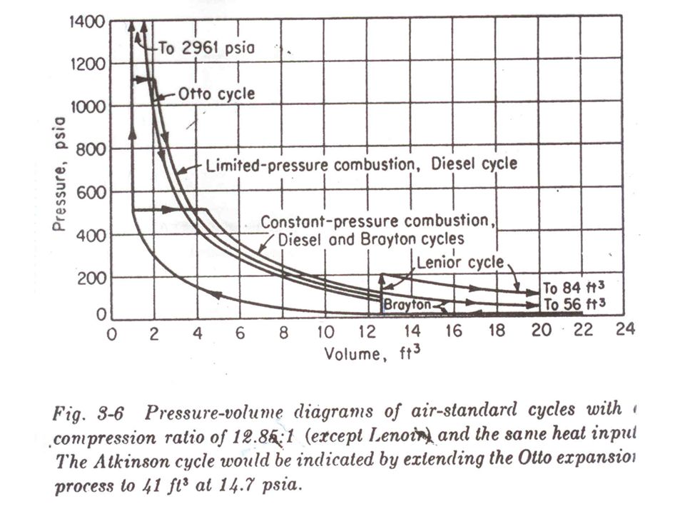
Unit - II Air Cycles

50
OTTO CYCLE

53
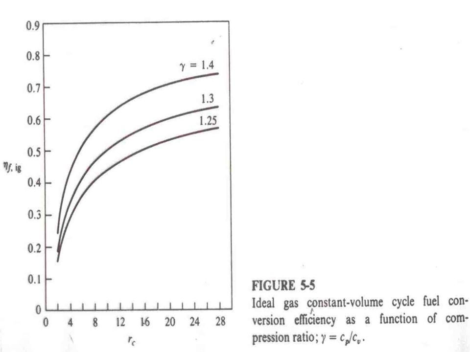
OTTO CYCLE Efficiency is given by
Efficiency increases with increase in compression ratio and specific heat ratio (γ) and is independent of load, amount of heat added and initial conditions.
 and is independent of load, amount of heat added and initial conditions.")
55
r 1 2 0.242 3 0.356 4 0.426 5 0.475 6 0.512 7 0.541 8 0.565 9 0.585 10 0.602 16 0.67 20 0.698 50 0.791 CR ↑from 2 to 4, efficiency ↑ is 76% CR from 4 to 8 efficiency is 32.6 CR from 8 to 16 efficiency

57
OTTO CYCLE Mean Effective Pressure
It is that constant pressure which, if exerted on the piston for the whole outward stroke, would yield work equal to the work of the cycle. It is given by

58
OTTO CYCLE Mean Effective Pressure
We have: Eq. of state: To give:

59
OTTO CYCLE Mean Effective Pressure
The quantity Q2-3/M is heat added/unit mass equal to Q’, so

60
OTTO CYCLE Mean Effective Pressure
Non-dimensionalizing mep with p1 we get Since:

61
OTTO CYCLE Mean Effective Pressure
We get Mep/p1 is a function of heat added, initial temperature, compression ratio and properties of air, namely, cv and γ

62
Choice of Q’ We have For an actual engine: F=fuel-air ratio, Mf/Ma
Ma=Mass of air, Qc=fuel calorific value

63
Choice of Q’ We now get: Thus:

64
Choice of Q’ For isooctane, FQc at stoichiometric conditions is equal to 2975 kJ/kg, thus Q’ = 2975(r – 1)/r At an ambient temperature, T1 of 300K and cv for air is assumed to be kJ/kgK, we get a value of Q’/cvT1 = 13.8(r – 1)/r. Under fuel rich conditions, φ = 1.2, Q’/ cvT1 = 16.6(r – 1)/r. Under fuel lean conditions, φ = 0.8, Q’/ cvT1 = 11.1(r – 1)/r
/r. Under fuel rich conditions, φ = 1.2, Q’/ cvT1 = 16.6(r – 1)/r. Under fuel lean conditions, φ = 0.8, Q’/ cvT1 = 11.1(r – 1)/r.")
65
OTTO CYCLE Mean Effective Pressure
Another parameter, which is of importance, is the quantity mep/p3. This can be obtained from the following expression:

68
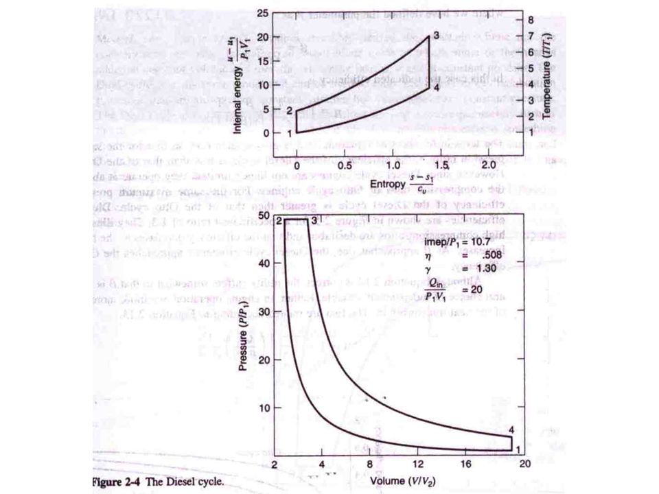
Diesel Cycle Thermal Efficiency of cycle is given by
rc is the cut-ff ratio, V3/V2 We can write rc in terms of Q’:

69
We can write the mep formula for the diesel cycle like that for the Otto cycle in terms of the η, Q’, γ, cv and T1:

70
Diesel Cycle We can write the mep in terms of γ, r and rc:
The expression for mep/p3 is:

71
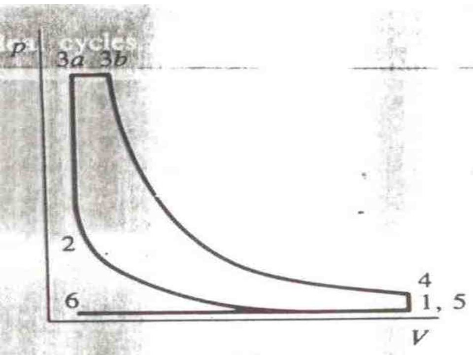
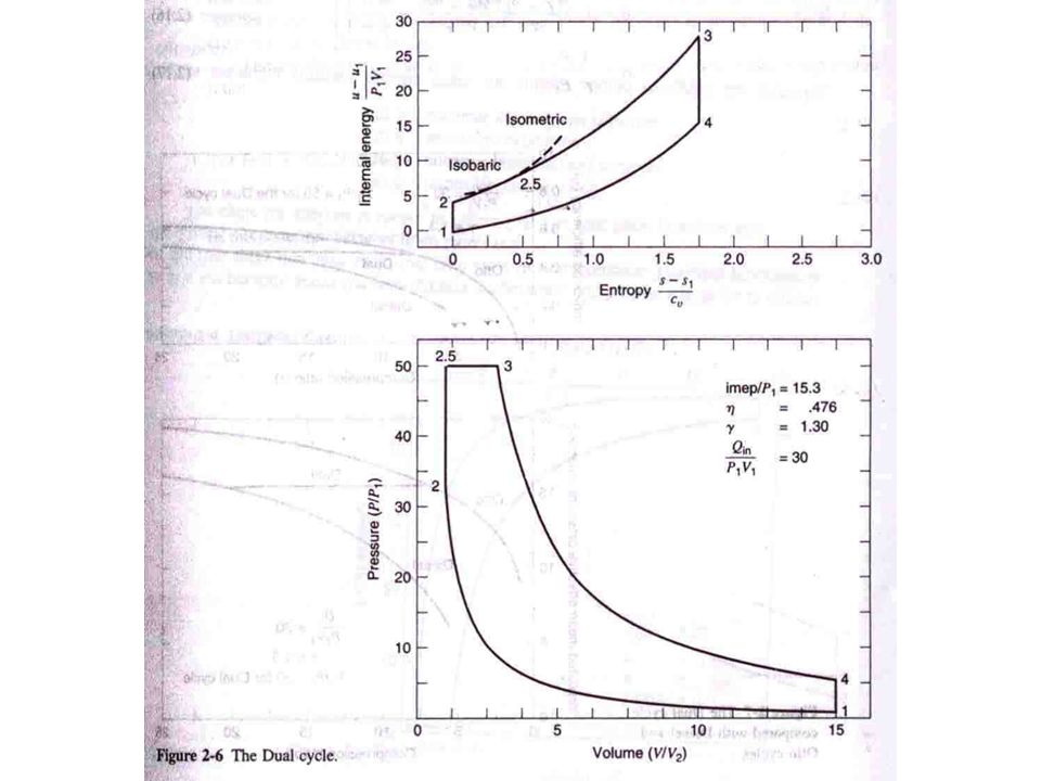
DUAL CYCLE

74
Dual Cycle The Efficiency is given by
We can use the same expression as before to obtain the mep. To obtain the mep in terms of the cut-off and pressure ratios we have the following expression

75
Dual Cycle For the dual cycle, the expression for mep/p3 is as follows:

76
Dual Cycle For the dual cycle, the expression for mep/p3 is as follows:

77
Dual Cycle We can write an expression for rp the pressure ratio in terms of the peak pressure which is a known quantity: We can obtain an expression for rc in terms of Q’ and rp and other known quantities as follows:

78
Dual Cycle We can also obtain an expression for rp in terms of Q’ and rc and other known quantities as follows:

81
Unit – IV & V

82
Refrigeration & Air Conditioning
The purpose of refrigeration is to cool spaces, objects, or materials and to maintain them at a temperature below the temperature of the surrounding atmosphere. In order to produce a refrigeration effect, it is merely necessary to expose the material to be cooled to a colder object or environment and allow heat to flow in its "natural" direction, that is, from the warmer material to the colder material. So, the heat we do not want will be removed, cooling the space or equipment.

83
Objectives Basic operation of refrigeration and AC systems
Principle components of refrigeration and AC systems Thermodynamic principles of refrigeration cycle Safety considerations A. The student will comprehend the basic operation, principle components, and safety considerations related to refrigeration and air conditioning systems. The student will apply correct procedures including comprehension of the thermodynamic principles involved to determine output and efficiency of refrigeration systems.

84
Uses of Systems Cooling of food stores and cargo
Cooling of electronic spaces and equipment CIC (computers and consoles) Radio (communications gear) Radars ESGN/RLGN Sonar Cooling of magazines Air conditioning for crew comfort
 Radio (communications gear) Radars. ESGN/RLGN. Sonar. Cooling of magazines. Air conditioning for crew comfort.")
85
Definition Review Specific heat (cp): Amount of heat required to raise the temperature of 1 lb of substance 1°F (BTU/lb) – how much for water? Sensible heat vs Latent heat LHV/LHF Second Law of Thermodynamics: must expend energy to get process to work Specific Heat. Specific heat is the amount of heat required to raise one pound of a substance 1°F at atmospheric pressure. (Notice the difference with the definition of the BTU: the BTU is the heat required to raise the temperature of water, whereas specific heat is for any substance.) British Thermal Unit (BTU). The amount of heat needed to raise one pound of water 1°F at atmospheric pressure. Sensible Heat. Sensible heat is that heat given off or absorbed by a substance which does not cause the substance to change phase. Sensible heat changes are observed as changes in temperature and are measured by a thermometer. Latent Heat. Latent heat is given off or absorbed by a substance that is changing phase. The temperature and pressure remain constant during the phase change until all the substance has been transformed. These temperature and pressure conditions are unique and are called saturation conditions. The latent heat of vaporization (LHV) is the heat required to transform a liquid to a gas at constant temperature and pressure. The latent heat of condensation (LHC) is equivalent in magnitude to the LHV for the substance, but now we are going in the opposite direction in transforming the gas to a liquid. When a liquid is transformed to a solid as in the ice-making process, the liquid gives off its latent heat of fusion (LHF) to form the solid. The LHF to transform a pint of water to 1 lb. of ice at 32°F is 144 BTUs. We would have to add 144 BTUs to every pound of ice to melt it.
 British Thermal Unit (BTU). The amount of heat needed to raise one pound of water 1°F at atmospheric pressure. Sensible Heat. Sensible heat is that heat given off or absorbed by a substance which does not cause the substance to change phase. Sensible heat changes are observed as changes in temperature and are measured by a thermometer. Latent Heat. Latent heat is given off or absorbed by a substance that is changing phase. The temperature and pressure remain constant during the phase change until all the substance has been transformed. These temperature and pressure conditions are unique and are called saturation conditions. The latent heat of vaporization (LHV) is the heat required to transform a liquid to a gas at constant temperature and pressure. The latent heat of condensation (LHC) is equivalent in magnitude to the LHV for the substance, but now we are going in the opposite direction in transforming the gas to a liquid. When a liquid is transformed to a solid as in the ice-making process, the liquid gives off its latent heat of fusion (LHF) to form the solid. The LHF to transform a pint of water to 1 lb. of ice at 32°F is 144 BTUs. We would have to add 144 BTUs to every pound of ice to melt it.")
86
Refrigeration Cycle Refrigeration - Cooling of an object and maintenance of its temp below that of surroundings Working substance must alternate b/t colder and hotter regions Most common: vapor compression Reverse of power cycle Heat absorbed in low temp region and released in high temp region

87
Generic Refrigeration Cycle

88
Thermodynamic Cycle The dome-like curve represents saturated conditions for the refrigerant. On the left half of the dome, the refrigerant exists as a saturated liquid and on the right as saturated vapor. Both liquid and gaseous refrigerant coexist inside the dome in saturation. To the left of the dome, the refrigerant is a subcooled liquid and to the right of the dome, it is a superheated vapor. The numbers (1 through 4) represent significant points in the flow of refrigerant as it makes its circuit in the cycle. The refrigerant working fluid undergoes thermodynamic changes between these points. ¨ Point 1-2 (Evaporation): Since this is inside the dome, constant pressure (21.5 psia) and temperature (-5°F) are maintained, i.e., saturation. When heat is transferred at saturation, the result is a change in phase. ¨ Point 2-3 (Compression): Compressing the gaseous Freon from 21.5 to 141 psia (6.5 to 126 psig) produces a concomitant increase in thermal energy represented by a rise in the enthalpy and the temperature of the Freon from 5° to 125°F. This is the heat of compression resulting from the added energy to the Freon vapor. Compression provides the thermal driving head to sustain the flow of Freon through the cycle. ¨ Point 3-4 (Condensation): In passing through the dome from the right side to the left, the refrigerant cools from 125° to 105°F and changes phase from a superheated vapor to a slightly subcooled liquid. Point 4-1 (Expansion): The refrigerant is expanded by passing through an expansion valve where its pressure is reduced from 141 psia to 21.5 psia. In the process of expanding, the Freon cools from 105° to -5°F (cold of expansion) and crosses into the dome where both saturated liquid and gaseous Freon can coexist. About 25% of the fluid vaporizes into a gas during the process.
 represent significant points in the flow of refrigerant as it makes its circuit in the cycle. The refrigerant working fluid undergoes thermodynamic changes between these points. ¨ Point 1-2 (Evaporation): Since this is inside the dome, constant pressure (21.5 psia) and temperature (-5°F) are maintained, i.e., saturation. When heat is transferred at saturation, the result is a change in phase. ¨ Point 2-3 (Compression): Compressing the gaseous Freon from 21.5 to 141 psia (6.5 to 126 psig) produces a concomitant increase in thermal energy represented by a rise in the enthalpy and the temperature of the Freon from 5° to 125°F. This is the heat of compression resulting from the added energy to the Freon vapor. Compression provides the thermal driving head to sustain the flow of Freon through the cycle. ¨ Point 3-4 (Condensation): In passing through the dome from the right side to the left, the refrigerant cools from 125° to 105°F and changes phase from a superheated vapor to a slightly subcooled liquid. Point 4-1 (Expansion): The refrigerant is expanded by passing through an expansion valve where its pressure is reduced from 141 psia to 21.5 psia. In the process of expanding, the Freon cools from 105° to -5°F (cold of expansion) and crosses into the dome where both saturated liquid and gaseous Freon can coexist. About 25% of the fluid vaporizes into a gas during the process.")
89
Typical Refrigeration Cycle

90
Components Refrigerant Evaporator/Chiller Compressor Condenser
Receiver Thermostatic expansion valve (TXV)
")
91
Refrigerant Desirable properties:
High latent heat of vaporization - max cooling Non-toxicity (no health hazard) Desirable saturation temp (for operating pressure) Chemical stability (non-flammable/non-explosive) Ease of leak detection Low cost Readily available Commonly use FREON (R-12, R-114, etc.)
 Desirable saturation temp (for operating pressure) Chemical stability (non-flammable/non-explosive) Ease of leak detection. Low cost. Readily available. Commonly use FREON (R-12, R-114, etc.)")
92
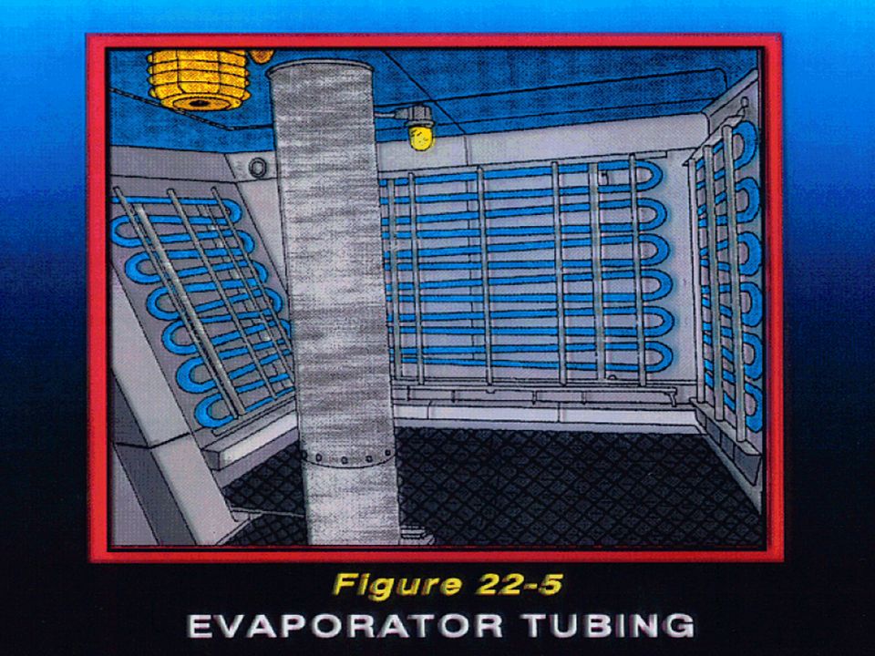
Evaporator/Chiller Located in space to be refrigerated
Cooling coil acts as an indirect heat exchanger Absorbs heat from surroundings and vaporizes Latent Heat of Vaporization Sensible Heat of surroundings Evaporation From the expansion valve, Freon as a saturated mixture of liquid and vapor passes into the cooling coil, or evaporator, located in the freeze box to be cooled. The cooling coil acts as a heat exchanger. The boiling point of the refrigerant under the low pressure in the evaporator is extremely low - much lower than the temperature of the spaces in which the cooling coils are installed. The temperature differential between the -5°F refrigerant in the coils and the air in the freeze box slightly above 0°F causes heat to be transferred from the freeze box to the refrigerant. It absorbs its latent heat of vaporization from the surroundings, thereby cooling the space. The refrigerant continues to absorb heat until all the liquid has boiled and vaporized. To ensure all the refrigerant changes phase to vapor, the Freon must be slightly superheated. As a rule, 6° to 10°F of superheat is added to the Freon. The refrigerant leaves the evaporator as a low pressure superheated vapor, having cooled the freeze box by absorbing its unwanted heat. The remainder of the cycle is concerned with disposing of this heat and getting the refrigerant back into a liquid state so that it can again vaporize in the evaporator and thus again absorb heat from the freeze box. Slightly superheated (10°F) - ensures no liquid carryover into compressor
 - ensures no liquid carryover into compressor.")
94
Compressor Superheated Vapor:
Enters as low press, low temp vapor Exits as high press, high temp vapor Temp: creates differential (DT) promotes heat transfer Press: Tsat allows for condensation at warmer temps Increase in energy provides the driving force to circulate refrigerant through the system Compression The low pressure, superheated Freon vapor is discharged from the evaporator to the suction side of the compressor. The compressor is the mechanical unit which keeps the refrigerant circulating through the system by increasing the fluid’s pressure and thermal potential energies. In the compressor (either reciprocating or centrifugal), the refrigerant is compressed from a low pressure vapor to a high pressure vapor, and its temperature rises accordingly from the heat of compression. This increase in energy provides the driving force to allow the Freon to flow through the system.
 promotes heat transfer. Press: Tsat allows for condensation at warmer temps. Increase in energy provides the driving force to circulate refrigerant through the system. Compression. The low pressure, superheated Freon vapor is discharged from the evaporator to the suction side of the compressor. The compressor is the mechanical unit which keeps the refrigerant circulating through the system by increasing the fluid’s pressure and thermal potential energies. In the compressor (either reciprocating or centrifugal), the refrigerant is compressed from a low pressure vapor to a high pressure vapor, and its temperature rises accordingly from the heat of compression. This increase in energy provides the driving force to allow the Freon to flow through the system.")
95
Condenser Refrigerant rejects latent heat to cooling medium
Latent heat of condensation (LHC) Indirect heat exchanger: seawater absorbs the heat and discharges it overboard Condensation The refrigerant must be thermodynamically returned to its starting point as a high pressure (141 psia) and high temperature (105°F) subcooled liquid from a higher temperature (125°F) superheated vapor. There is a significant amount of heat to extract in transforming the Freon from a gas to a liquid in the form of latent heat of condensation (LHC). Since this extraneous heat must be disposed, a sea water heat exchanger is used to absorb the LHC and discharge it overboard. The heat removal from the refrigerant causes it to condense into a liquid at a constant pressure of 141 psia. The refrigerant, still at a high pressure, is now a subcooled liquid ready to commence the process again. From the condenser, the refrigerant flows into a receiver, which serves as a storage place for the liquid refrigerant and as a seal between the high and low pressure sides of the Freon loop. From the receiver, the refrigerant returns to the expansion valve and the cycle begins again. All refrigeration and air conditioning systems follow this simple process no matter what type of refrigerant is used. The operating parameters will change, but it still is the same basic cycle.
 Indirect heat exchanger: seawater absorbs the heat and discharges it overboard. Condensation. The refrigerant must be thermodynamically returned to its starting point as a high pressure (141 psia) and high temperature (105°F) subcooled liquid from a higher temperature (125°F) superheated vapor. There is a significant amount of heat to extract in transforming the Freon from a gas to a liquid in the form of latent heat of condensation (LHC). Since this extraneous heat must be disposed, a sea water heat exchanger is used to absorb the LHC and discharge it overboard. The heat removal from the refrigerant causes it to condense into a liquid at a constant pressure of 141 psia. The refrigerant, still at a high pressure, is now a subcooled liquid ready to commence the process again. From the condenser, the refrigerant flows into a receiver, which serves as a storage place for the liquid refrigerant and as a seal between the high and low pressure sides of the Freon loop. From the receiver, the refrigerant returns to the expansion valve and the cycle begins again. All refrigeration and air conditioning systems follow this simple process no matter what type of refrigerant is used. The operating parameters will change, but it still is the same basic cycle.")
96
Receiver Temporary storage space & surge volume for the sub-cooled refrigerant Serves as a vapor seal to prevent vapor from entering the expansion valve

97
Expansion Device Thermostatic Expansion Valve (TXV)
Liquid Freon enters the expansion valve at high pressure and leaves as a low pressure wet vapor (vapor forms as refrigerant enters saturation region) Controls: Pressure reduction Amount of refrigerant entering evaporator controls capacity Expansion Liquid Freon enters the expansion valve at high pressure. The refrigerant leaves the outlet of the expansion valve at a much lower pressure and enters the low pressure side of the system. Because the pressure release has decreased the refrigerant’s potential energy, the liquid refrigerant manifests this energy conversion by beginning to boil and to flash into vapor. The Freon is still saturated and at a very low temperature of -5°F entering the evaporator, or chiller, coils. It is now a mixture of liquid and vapor refrigerant. This temperature gives us a thermal differential to cool, or keep cool, a freeze box which must be maintained at 0°F. The refrigerant is now ready to absorb the unnecessary heat from the freeze box by entering the evaporator coils located in the space to be cooled (freeze box).
 Controls: Pressure reduction. Amount of refrigerant entering evaporator controls capacity. Expansion. Liquid Freon enters the expansion valve at high pressure. The refrigerant leaves the outlet of the expansion valve at a much lower pressure and enters the low pressure side of the system. Because the pressure release has decreased the refrigerant’s potential energy, the liquid refrigerant manifests this energy conversion by beginning to boil and to flash into vapor. The Freon is still saturated and at a very low temperature of -5°F entering the evaporator, or chiller, coils. It is now a mixture of liquid and vapor refrigerant. This temperature gives us a thermal differential to cool, or keep cool, a freeze box which must be maintained at 0°F. The refrigerant is now ready to absorb the unnecessary heat from the freeze box by entering the evaporator coils located in the space to be cooled (freeze box).")
99
Air Conditioning Purpose: maintain the atmosphere of an enclosed space at a required temp, humidity and purity Refrigeration system is at heart of AC system Heaters in ventilation system Types Used: Self-contained Refrigerant circulating Chill water circulating - Self-contained equipment are sealed refrigerating or freezing systems within a cabinet or housing to perform a specific function or service. These are sometimes referred to as package units.

100
AC System Types Self-Contained System Refrigerant circulating system
Add-on to ships that originally did not have AC plants Not located in ventilation system (window unit) Refrigerant circulating system Hot air passed over refrigerant cooling coils directly Chilled water circulating system Refrigerant cools chill water Hot air passes over chill water cooling coils - Self-contained equipment are sealed refrigerating or freezing systems within a cabinet or housing to perform a specific function or service. These are sometimes referred to as package units.
 Refrigerant circulating system. Hot air passed over refrigerant cooling coils directly. Chilled water circulating system. Refrigerant cools chill water. Hot air passes over chill water cooling coils. - Self-contained equipment are sealed refrigerating or freezing systems within a cabinet or housing to perform a specific function or service. These are sometimes referred to as package units.")
101
Basic AC System

102
Safety Precautions Phosgene gas hazard Handling procedures
Lethal Created when refrigerant is exposed to high temperatures Handling procedures Wear goggles and gloves to avoid eye irritation and frostbite Asphyxiation hazard in non-ventilated spaces (bilges since heavier than air) Handling of compressed gas bottles
 Handling of compressed gas bottles.")
103
THANK U

Similar presentations


>")
.>")


