Download presentation
Presentation is loading. Please wait.

2
Introduction: So far we have These equations are OK for static fields, i.e. those fields independent of time. When fields vary as a function of time the curl equations acquire an additional term. gets a

4
Consider the following experiment. Pull a wire loop through a region of non-uniform magnetic field. Wire loop, path encloses a surface S Magnetic field vector points into the page area gained in time area lost in time Faraday’s Law

5
Consider the following experiment. Pull a wire loop through a region of non-uniform magnetic field. Magnetic field vector points into the page Charge in wire Faraday’s Law

6
Consider the work done on +1C test charge moved around the loop; this is the “emf” electromotive force. Charge in wire Faraday’s Law Early definition of potential Examine Expression

7
Consider the work done on +1C test charge moved around the loop; this is the “emf” electromotive force. Now: Flux change at right side of loop Flux change at left side of loop Note that B and da are in opposite directions Faraday’s Law

8
This is a general result. Even if we hold the loop stationary and change B, the emf is still given by the negative rate of change of the flux. Move magnet N S Faraday’s Law

9
Further generalization is possible. Consider moving loop in time varying magnetic field. Move magnet N S Move loop MOTIONAL emf TRANSFORMER emf The induced emf always opposes the change in flux Faraday’s Law

11
N S MOVE LOOP motional emf The induced emf always opposes the change in flux Move loop towards magnet B increases in loop Flux increases in loop Current induced through emf Current produces magnetic field in loop: 2 nd postulate This magnetic field in opposite in direction to magnetic field of magnet I Faraday’s Law / Lenz’s Law

12
N S MOVE LOOP motional emf The induced emf always opposes the change in flux Move loop away from magnet B decreases in loop Flux decreases in loop Current induced Current produces magnetic field in loop This magnetic field in same direction to magnetic field of magnet I Faraday’s Law / Lenz’s Law

13
N S MOVE MAGNET The induced emf always opposes the change in flux Move magnet towards loop B increases in loop Flux increases in loop Current induced Current produces magnetic field in loop This magnetic field in opposite direction to magnetic field of magnet I transformer emf Faraday’s Law / Lenz’s Law

14
N S MOVE MAGNET The induced emf always opposes the change in flux Move magnet away from loop B decreases in loop Flux decreases in loop Current induced Current produces magnetic field in loop This magnetic field is in same direction to magnetic field of magnet I transformer emf Faraday’s Law / Lenz’s Law

15
Suppose loop is stationary so we have only transformer emf. MOVE MAGNET N S Equivalent battery to drive current around loop Faraday’s Law

16
Faraday’s Law in derivative form: Valid for all points in space

17
The induced emf always opposes the change in flux Note on: Faraday’s Law / Lenz’s Law WE KNOW THAT constant Inductance: relates the induced emf to the time rate of change of the current

18
Note on: Faraday’s Law / Lenz’s Law Rotating current loop in constant magnetic field X O Sinusoidal voltage change Amplitude of voltage depends on B, A and POWER GENERATOR

19
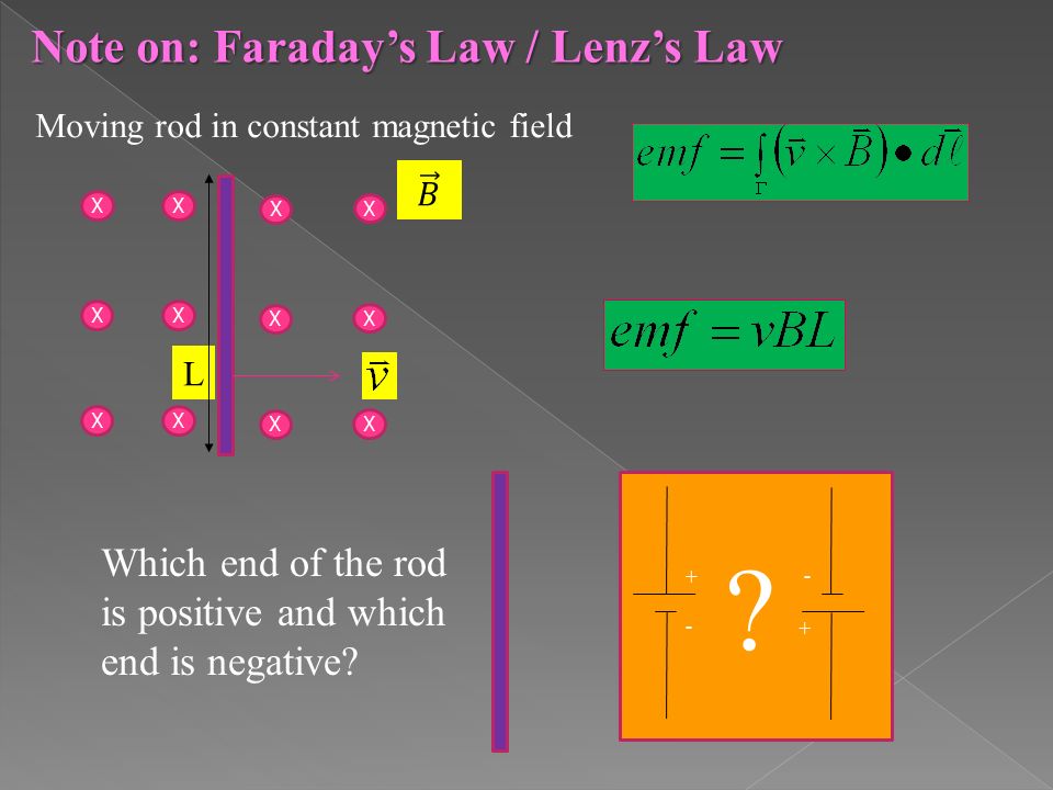
Note on: Faraday’s Law / Lenz’s Law Moving rod in constant magnetic field X X X X X X X X X X X X L Which end of the rod is positive and which end is negative? +-+- +-+- ?
21
Capacitor WIRE So far we have the following expression for Ampere’s law. Certainly there is no problem in evaluating the integral. The path shown encloses an area A through which the wire cuts. We are in fact in the process of charging the capacitor through the current I of the wire. For surface A chosen

22
Capacitor WIRE So far we have the following expression for Ampere’s law. Certainly there is a problem in evaluating the integral. The path shown encloses an area A’ through which the wire does not cut. Yet the integral value evaluated here for the surface that does not contain the wire A’ and the surface of the previous slide A which does contain the wire must be the same since the surfaces A’ and A are arbitrary. We are in fact in the process of charging the capacitor through the current I of the wire. For path A’ chosen Both integrals should give the same result??????

23
Capacitor WIRE For different surfaces Capacitor WIRE We have a problem

24
Solution to the problem Between the capacitor plates we have a changing electric flux density. This changing electric flux density is equivalent to a current density.

25
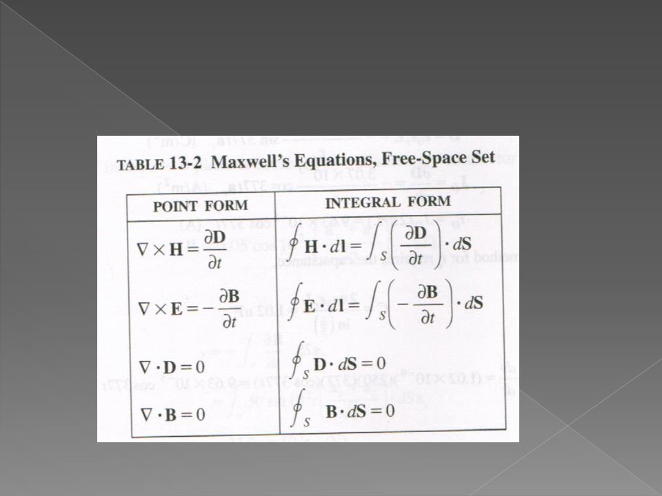
Solution to the problem Ampere’s law in integral form Ampere’s law in derivative form Apply Stoke’s theorem

27
NOW it might make sense, if i = D/ t S p Taken from ELEC 3909

28
Some materials are neither good conductors nor perfect dielectrics, so that both conduction current and displacement current exist. A model for a poor conductor or lossy dielectric is shown below. Assume a time dependence of e jwt for the electric field. E Then Remember this result (for ELEC 3909)
.")
29
A circular cross-section conductor of radius 1.5 mm caries a current i c = 5.5 sin(4E10t)( A). What is the amplitude of the displacement current density if = 35 MS/m and r = 1. E Then Remember this result (for ELEC 3909)
.")
30
B a V The circular metal disk rotates at (rad/s) in a uniform flux density B. Sliding contacts connect a voltmeter to the disk. What voltage is indicated on the meter. Solution: One radial element of the disk is examined. A general point on the radial element has velocity: r

31
In steady state the magnetic force on the free charges in the disk will equal the electric force induced by charge migration. We can then equate electric and magnetic forces to solve for the electric field in the rotating disk.

32
B a V The circular metal disk rotates at (rad/s) in a uniform flux density B. Sliding contacts connect a voltmeter to the disk. What voltage is indicated on the meter.

35
Solve for allowed Frequencies

36
Wavelength Tabulation Index Band Gap Resonator States

37
Wavelength Tabulation Index Band Gap Resonator States Axial magnetic field

Similar presentations


 The magnetic.>")


 i.>")

 How to find the force, F on the electric charge, Q excreted by the field E and/or B? (2) How fields E and/or B can be created? Gauss’s.>")
 Faraday’s law (sec. 29.2) Lenz’s law(sec. 29.3) Motional electromotive force(sec. 29.4) Induced electric fields(sec. 29.5)>")


>")


