Download presentation
Presentation is loading. Please wait.

1
Design status 2 mrad IR Current plan for finalization in 2008 Philip Bambade LAL-Orsay On behalf of: D.Angal-Kalinin, R.Appleby, F.Jackson, D.Toprek (Cockcroft) P.B., S.Cavalier, O.Dadoun, M.Lacroix (LAL-Orsay) ILC EDR BDS-KOM, SLAC, October 11-13, 2007
 P.B., S.Cavalier, O.Dadoun, M.Lacroix (LAL-Orsay) ILC EDR BDS-KOM, SLAC, October 11-13, 2007")
2
Outline Motivations Status of “minimal” redesign Current plans and aims Concluding remarks ….………. Alternative IP luminometry & polarimetry idea ?

3
Motivations for 2 mrad Large crossing-angle : 1. Eases post-IP beam extraction & transport diagnostics 2. But adds pre-IP constraints : crab-cavity control & tuning, non-axial solenoid + DID / anti-DID pre / post-IP trajectory bumps Physics & detector advantaged by small crossing-angle IR : simpler forward geometries, better hermeticity, no DID / anti-DID Head-on IR a priori nicest needs large electrostatic separators 2 mrad scheme : no crab-cavity (initially…), no electrostatic separators and order-of-magnitude smaller pre / post-IP trajectory bumps Snowmass 2 mrad design unsatisfactory redesign with simpler concept aiming to be as short & economical as possible Assumption : other ways than the present spent-beam spectrometry & polarimetry possible if planned pre-IP measurements need complementing Minimise costs and mitigate technical risks
, no electrostatic separators and order-of-magnitude smaller pre / post-IP trajectory bumps Snowmass 2 mrad design unsatisfactory redesign with simpler concept aiming to be as short & economical as possible Assumption : other ways than the present spent-beam spectrometry & polarimetry possible if planned pre-IP measurements need complementing Minimise costs and mitigate technical risks.")
4
Length ~ 300 m dump(s): 0.5 m 3 m New “minimal” extraction line concept QF, SF warm quad & sext QD, SD NbTi (Nb3Sn) SC FDFD 3 warm bends 2 “Panofsky” quads collimators | Explicit goals : short & economical, as few and feasible magnets as possible, more tolerant and flexible Beam rastering kickers can be placed to prevent water boiling and window damage kickers BB1,2 BHEX1 Extraction line has been integrated with the FFS flexible
: 0.5 m 3 m New minimal extraction line concept QF, SF warm quad & sext QD, SD NbTi (Nb3Sn) SC FDFD 3 warm bends 2 Panofsky quads collimators | Explicit goals : short & economical, as few and feasible magnets as possible, more tolerant and flexible Beam rastering kickers can be placed to prevent water boiling and window damage kickers BB1,2 BHEX1 Extraction line has been integrated with the FFS flexible")
5
Optimised compact final doublets Re-designed with acceptable losses and stay-clear for in / out charged & beamstrahlung beams EUROTeV-Memo-2007-001 & JINST 1 P10005 (2006) Works for all proposed ILC beam parameter sets, including (new) “High Luminosity” at 1 TeV ( GP++ large statistics at http://flc-mdi.lal.in2p3.fr/spip.php?rubrique17)http://flc-mdi.lal.in2p3.fr/spip.php?rubrique17 Compact SC QD,SD : NbTi LHC-like QD at 500 GeV, Nb3Sn SLHC-like QD at 1 TeV, NbTi 60 mm radius SD Standard warm QF & SF, with 20 and 30 mm radius Outgoing beam subject to non-linear pocket fields of QF1 and SF1 Losses in SC magnets [W]
![Optimised compact final doublets Re-designed with acceptable losses and stay-clear for in / out charged & beamstrahlung beams EUROTeV-Memo & JINST 1 P10005 (2006) Works for all proposed ILC beam parameter sets, including (new) High Luminosity at 1 TeV ( GP++ large statistics at rubrique17) rubrique17 Compact SC QD,SD : NbTi LHC-like QD at 500 GeV, Nb3Sn SLHC-like QD at 1 TeV, NbTi 60 mm radius SD Standard warm QF & SF, with 20 and 30 mm radius Outgoing beam subject to non-linear pocket fields of QF1 and SF1 Losses in SC magnets [W]](http://images.slideplayer.com/26/8855377/slides/slide_5.jpg "Optimised compact final doublets Re-designed with acceptable losses and stay-clear for in / out charged & beamstrahlung beams EUROTeV-Memo & JINST 1 P10005 (2006) Works for all proposed ILC beam parameter sets, including (new) High Luminosity at 1 TeV ( GP++ large statistics at rubrique17) rubrique17 Compact SC QD,SD : NbTi LHC-like QD at 500 GeV, Nb3Sn SLHC-like QD at 1 TeV, NbTi 60 mm radius SD Standard warm QF & SF, with 20 and 30 mm radius Outgoing beam subject to non-linear pocket fields of QF1 and SF1 Losses in SC magnets [W]")
7
First thoughts needs to be worked out in detail

8
First look at beam pipe in FD region Separating the incoming beam and designing the shared region up to QEX1,2 (40 m) and BHEX1 (80 m) for the outgoing and beamstrahlung beams Separation of beamstrahlung after BHEX1 Analyze direct lines of sights to VD through BeamCal mask hole (r = 1.2 cm) Next :
 and BHEX1 (80 m) for the outgoing and beamstrahlung beams Separation of beamstrahlung after BHEX1 Analyze direct lines of sights to VD through BeamCal mask hole (r = 1.2 cm) Next :")
9
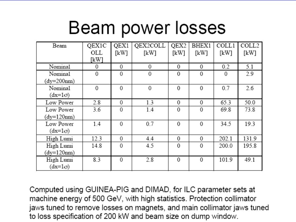
Magnets and collimators in rest of line Designed proof-of-principle optics with reasonable QEX1,2, BHEX1 and BB1,2 apertures & strengths and acceptable losses on dedicated collimators at both 500 GeV and 1 TeV EUROTeV-Memo-2007-004 Can be adjusted depending on best choice of dump arrangement Flexibility : magnet + beam pipe designs final parameters worst case maximum : high luminosity parameters with vertical offset

10
(nominal beam parameters)
")
11
BHEX1 C-type bend Beamstrahlung 1 mrad cone Incoming beam outgoing beam envelope B y = 0.215 T X [cm] B y (x) homogeneity < 4 % (with shims) within outgoing beam envelope checked to be sufficient Residual B y on incoming beam ~ 1% 20 rad (7.5 x’ ) use corrector Residual B x (y) dependence on incoming beam only even powers sextupole absorbed refitting SD / SF, decapole negligible effects 3A / mm 2 4000 mm 2 Accommodates the beamstrahlung, outgoing beam POISSON and proximity of incoming beam
![BHEX1 C-type bend Beamstrahlung 1 mrad cone Incoming beam outgoing beam envelope B y = T X [cm] B y (x) homogeneity < 4 % (with shims) within outgoing beam envelope checked to be sufficient Residual B y on incoming beam ~ 1% 20 rad (7.5 x’ ) use corrector Residual B x (y) dependence on incoming beam only even powers sextupole absorbed refitting SD / SF, decapole negligible effects 3A / mm mm 2 Accommodates the beamstrahlung, outgoing beam POISSON and proximity of incoming beam](http://images.slideplayer.com/26/8855377/slides/slide_11.jpg "BHEX1 C-type bend Beamstrahlung 1 mrad cone Incoming beam outgoing beam envelope B y = T X [cm] B y (x) homogeneity < 4 % (with shims) within outgoing beam envelope checked to be sufficient Residual B y on incoming beam ~ 1% 20 rad (7.5 x’ ) use corrector Residual B x (y) dependence on incoming beam only even powers sextupole absorbed refitting SD / SF, decapole negligible effects 3A / mm mm 2 Accommodates the beamstrahlung, outgoing beam POISSON and proximity of incoming beam")
12
Comparison done with ILC final focus optics integrating FD of 2 mrad scheme

13
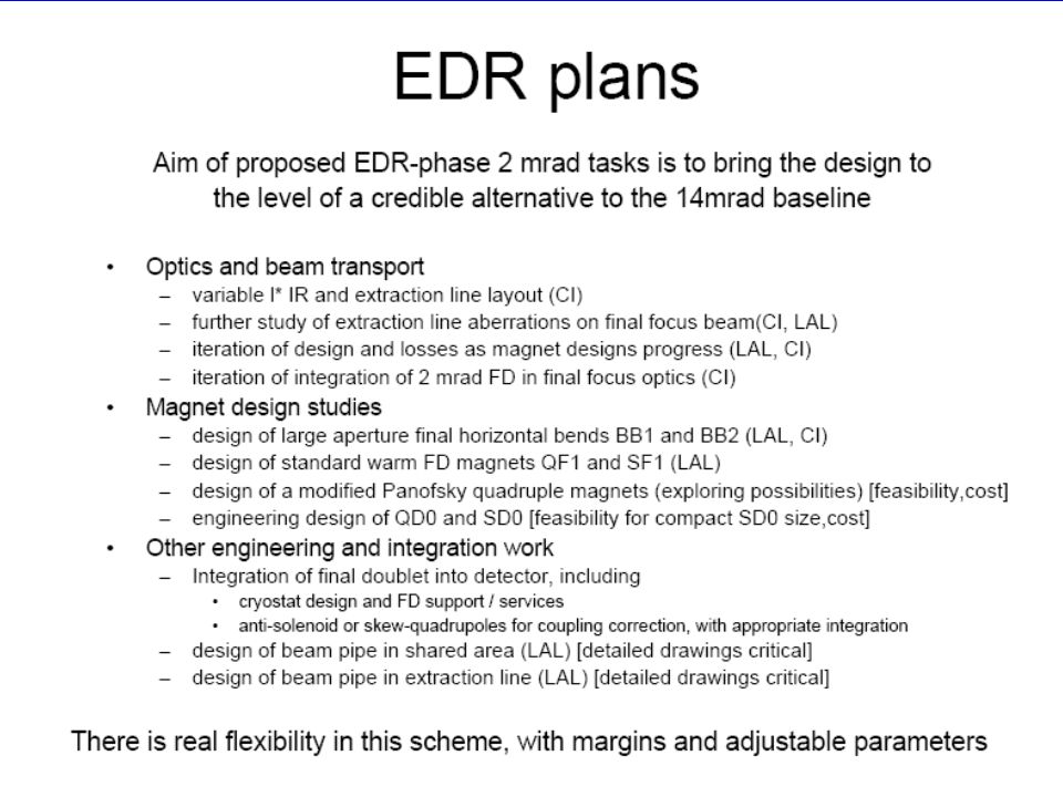
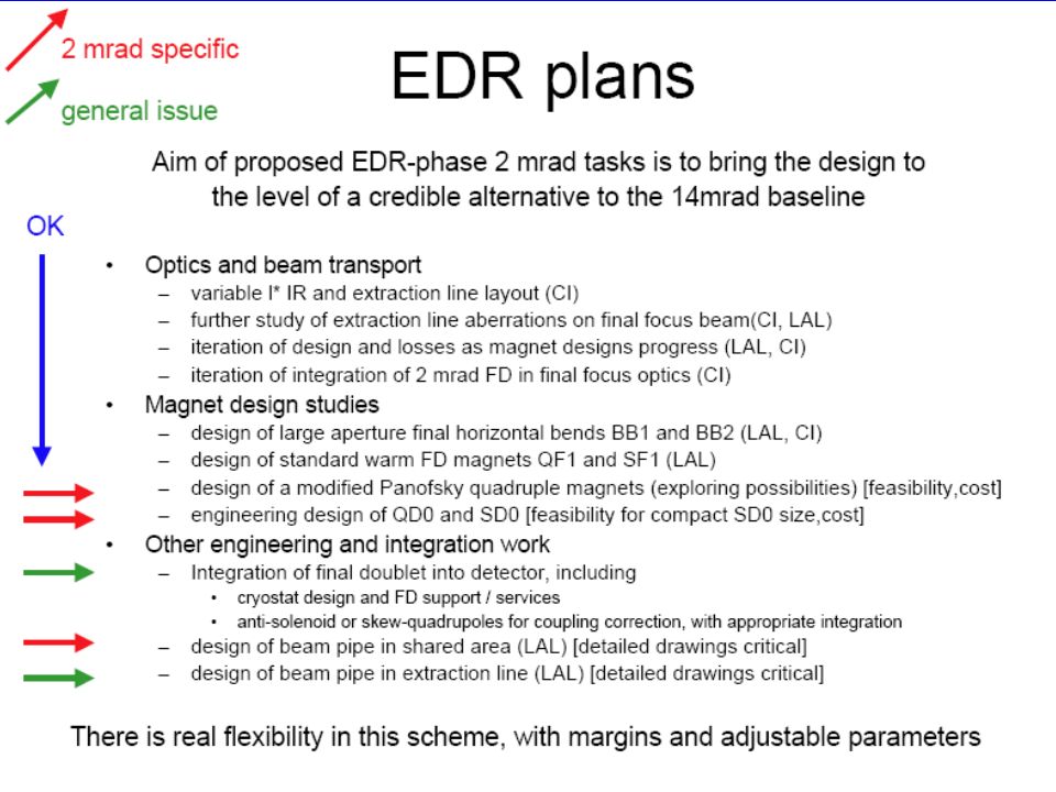
Further engineering for final design and costing QF, SF & BB1,2 “standard” magnets LAL & Cockcroft “Panofsky” – style large aperture quads LAL & Cockcroft NbTi SC QD & large bore SF for 500 GeV CM R&D Nb3Sn SC QD for 1 TeV upgrade : LBL & FNAL ? Investigate detector integration and push-pull scenarios Not considered in detail so far : dump and collimators improve d pocket fields experienced warm magnet group Experienced warm magnet group Vol. 30, No. 10, 927-930, 1959 L. Hand & W. Panofsky, Review of Scientific Instruments beam pipe optics iteration LAL & Cockcroft SC magnet group should connect to baseline work on these LAL & Cockcroft together with existing team on baseline

18
Additional slides

19
Luminosity loss without crab-crossing ( perfect conditions ) L/L 0 2 [mrad] 20 mrad L/L 0 ~ 0.2 ~ 0.85
![Luminosity loss without crab-crossing ( perfect conditions ) L/L 0 2 [mrad] 20 mrad L/L 0 ~ 0.2 ~ 0.85](http://images.slideplayer.com/26/8855377/slides/slide_19.jpg "Luminosity loss without crab-crossing ( perfect conditions ) L/L 0 2 [mrad] 20 mrad L/L 0 ~ 0.2 ~ 0.85")
20
QD 2.0mrad 1.0mrad incoming beam axis outgoing beam axis detector axis Symmetry consideration and BeamCal mask BeamCal with r 15mm in LDC, centred on detector axis OK clearances Effective BeamCal aperture of 7mm radius GLD LDC QF1 QD0 VXD BeamCal Best case GLD, worst case LDC, but the collimation depths are acceptable

21
Optics for 500 GeV and 1 TeV EUROTeV-Memo-2007-004

23
LAL/RT-07-07 & EUROTeV-Report-2007-047

24
Beamstrahlung photon cones Integrated power beyond half- opening angle

25
Combined Compton Luminometer & Polarimeter at IP ?!? 4 10 3 luminosity P. Schüler C. Rimbault - Laser focused 10 m from IP, to 50 m - crossing-angle = 5 -10 mrad - E = 2.33 eV - z, = 10 ps - with = 25 – 50 W 2 - 4 10 4 Comptons / BX Comptons / BX VERY PRELIMINARY Collection efficiency ~ 5-10%

26
Combined Compton Luminometer & Polarimeter at IP ?!? 4 10 3 luminosity P. Schüler C. Rimbault - Laser focused 10 m from IP, to 50 m - crossing-angle = 5 -10 mrad - E = 2.33 eV - z, = 10 ps - with = 25 – 50 W 2 - 4 10 4 Comptons / BX Comptons / BX VERY PRELIMINARY Collection efficiency ~ 5-10%

27
Connected beam dynamics and MDI investigations Not 2 mrad specific combine with head-on & 14 mrad work Spent beam diagnostics to monitor IP beam sizes & offsets Impact of non-axial detector solenoid and pre / post-IP trajectory bumps on beam setup and optical tuning Detector background from beam and SR losses Post-IP relative energy & energy spread measurements IP Compton luminometry and polarimetry with high power laser and instrumented mask near the FD Optical tuning strategy and feedback algorithms

Similar presentations


 MDI meeting at SLAC 1/6/2005.>")
 Deepa Angal-Kalinin, Shigeru Kuroda, Andrei Seryi October 21, 2005.>")


 panels (R&D, Detector costing, MDI, 2 IRs) Interim panel.>")

 A.Seryi September 27, 2005.>")


