Download presentation
Presentation is loading. Please wait.

1
Simple Machines

2
History of Work Before engines and motors were invented, people had to do things like lifting or pushing heavy loads by hand. Using an animal could help, but what they really needed were some clever ways to either make work easier or faster.

3
Simple Machines Ancient people invented simple machines that would help them overcome resistive forces and allow them to do the desired work against those forces.

4
Simple Machines The six simple machines are: Lever Wheel and Axle
Pulley Inclined Plane Wedge Screw

5
Simple Machines A machine is a device that helps make work easier to perform by accomplishing one or more of the following functions: transferring a force from one place to another, changing the direction of a force, increasing the magnitude of a force, or increasing the distance or speed of a force.

6
Mechanical Advantage It is useful to think about a machine in terms of the input force (the force you apply) and the output force (force which is applied to the task). When a machine takes a small input force and increases the magnitude of the output force, a mechanical advantage has been produced.
 and the output force (force which is applied to the task). When a machine takes a small input force and increases the magnitude of the output force, a mechanical advantage has been produced.")
7
Mechanical Advantage MA = output force / input force
If a machine increases an input force of 10 Newtons to an output force of 100 Newtons, the machine has a mechanical advantage (MA) of 10. In machines that increase distance instead of force MA = output distance / input distance
 of 10. In machines that increase distance instead of force. MA = output distance / input distance.")
8
No machine can increase both the magnitude and the distance of a force at the same time.

9
Vector

10
The Lever A lever is a rigid bar that rotates around a fixed point called the fulcrum. The bar may be either straight or curved. In use, a lever has both an effort (or applied) force and a load (resistant force).
 force and a load (resistant force).")
11
To find the MA of a lever, divide the output force by the input force, or divide the length of the resistance arm by the length of the effort arm. MA= OF / IF Or MA= RA / EA

12
The 3 Classes of Levers The class of a lever is determined by the location of the effort force and the load relative to the fulcrum.

13
First Class Lever In a first-class lever the fulcrum is located at some point between the effort and resistance forces. Common examples of first-class levers include crowbars, scissors, pliers, tin snips, and seesaws. A first-class lever always changes the direction of force (I.e. a downward effort force on the lever results in an upward movement of the resistance force).
.")
14
Fulcrum is between EF (effort) and RF (load) Effort moves farther than Resistance. Multiplies EF and changes its direction

15
Second Class Lever With a second-class lever, the load is located between the fulcrum and the effort force. Common examples of second-class levers include nut crackers, wheel barrows, doors, and bottle openers. A second-class lever does not change the direction of force. When the fulcrum is located closer to the load than to the effort force, an increase in force (mechanical advantage) results.
 results.")
16
RF (load) is between fulcrum and EF Effort moves farther than Resistance. Multiplies EF, but does not change its direction

17
Third Class Lever With a third-class lever, the effort force is applied between the fulcrum and the resistance force. Examples of third-class levers include tweezers, hammers, and shovels. A third-class lever does not change the direction of force; third-class levers always produce a gain in speed and distance and a corresponding decrease in force.

18
EF is between fulcrum and RF (load) Does not multiply force Resistance moves farther than Effort. Multiplies the distance the effort force travels

19
Wheel and Axle The wheel and axle is a simple machine consisting of a large wheel rigidly secured to a smaller wheel or shaft, called an axle. When either the wheel or axle turns, the other part also turns. One full revolution of either part causes one full revolution of the other part. MA = Radius of wheel divided by radius of axle.

20
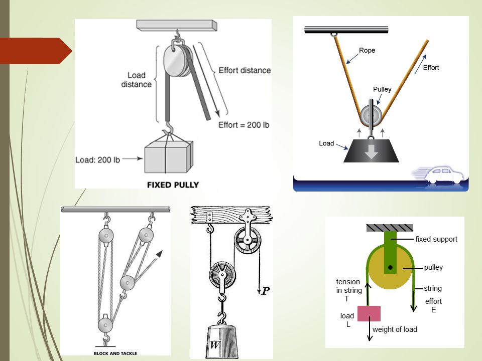
Pulley A pulley consists of a grooved wheel that turns freely in a frame called a block. A pulley can be used to simply change the direction of a force or to gain a mechanical advantage, depending on how the pulley is arranged. MA = 2 n n is the number of moveable pulleys.

21
Pulley Two types of pulleys Fixed Pulley Moveable pulley
Changes the direction of a force (no mechanical advantage) Think of how they move pianos in cartoons Moveable pulley May change direction of the force and/or create a mechanical advantage
 Think of how they move pianos in cartoons. Moveable pulley. May change direction of the force and/or create a mechanical advantage.")
23
Compound Pulleys

24
Inclined Plane An inclined plane is an even sloping surface. The inclined plane makes it easier to move a weight from a lower to higher elevation.

25
Inclined Plane MA = Length of incline divided by height. While the inclined plane produces a mechanical advantage, it does so by increasing the distance through which the force must move.

26
Although it takes less force for car A to get to the top of the ramp, all the cars do the same amount of work. A B C

27
Inclined Plane A wagon trail on a steep hill will often traverse back and forth to reduce the slope experienced by a team pulling a heavily loaded wagon. This same technique is used today in modern freeways which travel winding paths through steep mountain passes.

28
Wedge The wedge is a modification of the inclined plane. Wedges are used as either separating or holding devices. A wedge can either be composed of one or two inclined planes. A double wedge can be thought of as two inclined planes joined together with their sloping surfaces outward.

29
Wedges Single: Double: Chisel Chock Door Stop Axe Wood splitter Knife
Scissors Chisel Nail

31
Screw A screw is an inclined plane that is wrapped helically around an axis (think of a road winding up a tall mountain) The screw is also a modified version of the inclined plane.

32
Screw MA of an screw can be calculated by dividing the number of turns per centimeter.

33
Efficiency We said that the input force times the distance equals the output force times distance, or: Input Force x Distance = Output Force x Distance However, some output force is lost due to friction. The comparison of work input to work output is called efficiency. No machine has 100 % efficiency due to friction.

34
Extra Questions 1. What is the mechanical advantage of the following lever? 100 N 2500 N

35
Extra Questions 2. What is the mechanical advantage of this inclined plane? 15 m 3 m

36
Extra Questions 3. What is the effort force required for a system of 3 moveable pulleys to move an object with 900 N of resistant force?

37
Extra Questions 4. What is the mechanical advantage of the following lever? 10 M 5 M

38
Extra Questions 5. What is the mechanical advantage of a wheel and axle that has a wheel with a radius of 15 cm and an axle with a radius of 10 cm?

Similar presentations


 know how six different simple machines are used in every day life to make work easier 2) be able.>")


