Download presentation
Presentation is loading. Please wait.

1
Projections of Straight Lines Engineering Graphics TA 101

2
Projections of Straight Lines The shortest distance between two points is called a straight line. Positions of straight lines with respect to V.P. and H.P. 1.Perpendicular to one plane and parallel to the other. 2.Parallel to both the planes. 3.Parallel to one plane and inclined to the other. 4.Contained by one plane and inclined to the other. 5.Inclined, to both the planes.

3
Line perpendicular to H.P. and parallel to V.P. Prob 1 : A line AB 25 mm long is parallel to V.P. and perpendicular to H.P. Point A is 35 mm above H.P. and 20mm in front of V.P. Point B is 10mm above H.P. Draw the projections of the line AB.

7
Prob 2 : A line CD 20 mm long is parallel to V.P. and perpendicular to H.P. Point C is 35 mm above H.P. and 10 mm in front of V.P. Draw its projections.

8
Line perpendicular to V.P. and parallel to H.P. Prob 3 : A line AB 25 mm long is perpendicular to V.P. and parallel to H.P. Its end A is 10mm in front of V.P. and the line is 20mm above H.P. Draw the projections of the line.

12
Prob 4 : A line CD 30 mm long is perpendicular to V.P. and parallel to H.P. Its end C is 5 mm, in front of V.P. and the line is 10 mm above' H.P. Draw the projections of the line.

14
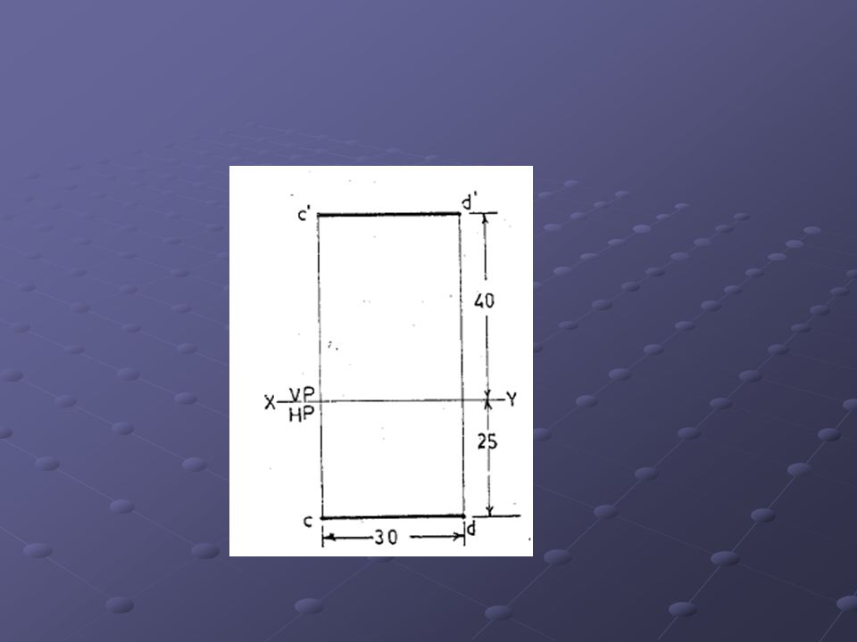
Line parallel to both the planes Prob 5 : A line CD 30 mm long is parallel to both the planes. The line is 40 mm above H.P. and 25 mm in front of V.P. Draw its projections.

17
Prob 6 : A line AB 50 mm long is parallel to both the planes. The line is 35 mm in front of V.P. and 30 mm above H.P. Draw the projections of the line.

18
Line parallel to V.P. and inclined to H.P. Prob 7 :A line PQ 40mm long is parallel to V.P. and inclined at an angle of 30° to H.P. The end P is 15 mm above H.P. and 20 mm in front of V.P. Draw the projections of the line

21
Prob 8 : A line MN 50mm long is parallel to V.P. and inclined at an angle of 30° to H.P. The end M is 20 mm above H.P. and 10 mm in front of V.P. Draw the projections of the line

22
Line parallel to H.P and Inclined to V.P Prob 9: Draw the projections of straight line EF 40 mm long parallel to HP and inclined at an angle of 35 0 to VP. The End E is 20 mm Above H.P and 15 mm in front of VP.

25
Prob 10: Draw the projections of a straight line CD 50mm long, parallel to H.P and inclined to V.P. the end C is 10 mm in front of VP and D is 30 mm in front of VP. The line is 15mm above HP.

26
Line contained by V.P. and inclined to H.P. Prob 11: A line AB 50 mm long is in V.P. and inclined at an angle of 35° to H.P. The end A is 10 mm above H.P. Draw the projections.

29
Prob 12: A line EF 40 mm long is in V.P. and inclined to H.P. The top view measures 30 mm. The end E is 10 mm above H.P. Draw the projections of the line. Determine its inclination with H.P.

30
Line Inclined to Both the Planes: The position of the line PQ which is inclined to both the planes is shown in first quadrant in the Fig. The projections of this line can be obtained by rotating this line into two simple positions, namely, a. parallel to the V.P. b. parallel to the H.P.

32
15. A line CD 80 mm long is inclined at an angle of 30 0 to H.P and 45 0 to V.P. the point C is 20 mm above H.P and 30 mm in front of V.P. Draw the projections of the straight line. Sol: 1.C is 20 mm above H.P. therefore mark C’ 20 mm above XY Plane. 2.C is 30 mm in front of V.P. therefore mark C 30 mm below XY Plane. To obtain the locus of d’ and top view length: 3.To start with assume the line to be inclined to only one plane (say H.P). from C’ draw a 30 0 line to XY and mark d 1 ’ such that C’d 1 ’=true length = 80mm. from C’ draw a 30 0 line to XY and mark d 1 ’ such that C’d 1 ’=true length = 80mm. 4.Draw a horizontal line through d 1 ’ which will be the locus of D in front view. 5.Draw a horizontal line from C. 6.From d 1 ’ draw a projector to intersect the horizontal drawn from C at d 1. now cd 1 is the length of the top view.
. from C’ draw a 30 0 line to XY and mark d 1 ’ such that C’d 1 ’=true length = 80mm. from C’ draw a 30 0 line to XY and mark d 1 ’ such that C’d 1 ’=true length = 80mm. 4.Draw a horizontal line through d 1 ’ which will be the locus of D in front view. 5.Draw a horizontal line from C. 6.From d 1 ’ draw a projector to intersect the horizontal drawn from C at d 1. now cd 1 is the length of the top view..")
34
To obtain the locus of d and front view length 7.Next assume the line to be parallel to H.P. and inclined at to V.P. We can obtain the locus of d. 8.From c draw a line 45° to XY and mark d 2 such that cd 2 = true length = 80 mm. 9.Draw a horizontal line through d 2 which- will be the locus of D in top view. 10.From d2 draw a projector to intersect the horizontal line drawn from c' at d' 2. c'd' 2 is the length of the front view. 11.To draw the top view : 12.With c as centre and cd 1 as radius draw an arc to, intersect the locus of d at d. Now cd is the top view. To draw the front view : 13.With c'. as centre and c'd' 2 as radius draw an arc to intersect the locus of d'. Now c'd' is the front view. 14.Now d' and d will be on the same projector.

36
17. A line PQ 75 mm long is inclined at an angle of 45° to H.P. and 30° to V.P. The point P is 15 mm above H.P. and 20 mm in front of V.P. Draw the projections of the line.

37
17. A line measuring 75 mm long has one of its ends 50 mm in front of V.P. and 15 mm above H.P. The top view of the line is 50 mm long. Draw and measure the front view. The other end is 15 mm in front of V.P. and is above H.P.

38
1.A is 15 mm above H.P. and 50 mm in front of V.P. Therefore mark a' 15 mm above XY and a 50 mm below XY. To draw the top view, given the top view length : 2.B is 15 mm in front of V.P. Therefore draw a horizontal line 15 mm below XY to represent the locus of b. 3.The top view of the line is 50 mm. Therefore with a as centre and 50 mm as radius, draw an arc to intersect the locus of b at b. Now ab is the top view of the given straight line. To obtain the locus of b'

40
4.With a as centre and ab as radius draw an arc to intersect the horizontal drawn through a at b1. 5.The true length is given as 75 mm. Therefore with a' as centre and 75 mm as radius, draw an arc to intersect the projector drawn from b l at b‘ 1. 6.Draw a horizontal line through b'1 to represent the locus of b'. To draw the front view 7.Frombdraw a projector to intersect the locus of b' at b'. 8.Join a'b' which is the front view of the given line.

41
18. A line measuring 80 mm long has one of its ends 60 mm above H.P. and 20 mm in front of V.P. The other end is 15 mm above H.P. and in front of V.P. The front view of the line is 60 mm long. Draw the top view.

42
20. Draw the projections of a straight line AB of 100mm long when one of its ends is touching the V.P. and the other end touching H.P. the angle of inclination with H.P and V.P are 40 0 and 50 0 respectively

43
Sol: To obtain the top view length and locus of b’ 1.Mark any point a1’ on XY to represent the front view of A in the above position. 2.Draw a 1 ’b 1 ’ = 100 mm at an angle of 40 0 to XY. 3.From b 1 ’ draw the horizontal to represent the locus of b’. 4.a 1 b 1 is the corresponding top view length. To obtain the front view length and locus of a:

44
5.Take another point b 2 on XY. Draw a line from b 2 at 50° (Ø ) to XY and mark a 2 b 2 = 100 mm = true length. 6.Draw a horizontal through a 2 to represent the locus of a. 7.Draw the front view a 2 b 2 on XY corresponding to a 2 b 2.Now a 2 b' 2 gives the length of the front view. To obtain the final projections : 8.Mark some other point a' on XY. With a' as centre and a 2 b 2 as radius draw an arc to cut the locus of b' at b'. 9.From the configuration, a'b'b1b'1. Therefore draw a'b' (front view) perpendicular to XY. Note that b will coincide with a'. 10.With b as centre and a l b l as radius draw an arc to cut the locus of a at a. Now ab is the top view. 11.From the configuration, ab = a’ 2 a 2. Hence ab is perpendicular to XY.
 to XY and mark a 2 b 2 = 100 mm = true length. 6.Draw a horizontal through a 2 to represent the locus of a. 7.Draw the front view a 2 b 2 on XY corresponding to a 2 b 2.Now a 2 b 2 gives the length of the front view. To obtain the final projections : 8.Mark some other point a on XY. With a as centre and a 2 b 2 as radius draw an arc to cut the locus of b at b . 9.From the configuration, a b b1b 1. Therefore draw a b (front view) perpendicular to XY. Note that b will coincide with a . 10.With b as centre and a l b l as radius draw an arc to cut the locus of a at a. Now ab is the top view. 11.From the configuration, ab = a’ 2 a 2. Hence ab is perpendicular to XY..")
46
True Length of a Straight line and Its true Inclinations with H.P and V.P. Given the projections of a line, to find the true length and inclinations with H.P and V.P: when a line is parallel to a plane, its projection on that plane will give its true length and the true inclination with the other plane. After making the line parallel to a plane, its true length can be obtained by any one of the two methods.

47
Rotating Line Method: Make each view parallel to XY line and project the other view from it. Trapezoid Method: Rotate the line about its projections till it lies in H.P. or V.P.

48
22. The distance between the projectors of two points A and B is 70 mm. Point A is 10 mm above H.P. and 15 mm in front of V.P. Point B is 50 mm above H.P. and 40 mm in front of V.P. Find the shortest distance between A and B by Rotating Line Method. Measure the true inclinations of the line AB with V.P. and H.P.

49
To obtain the projections : 1. Mark a' 10 mm above XY and a 15 mm below XY. Draw another projector 70 mm from the projector" of A. Mark b' 50 mm above XY and b 40 mm below XY on the second projector. Join a'b' and ab. To obtain the shortest distance between A & B (= true-length of AB) : 2. Through b' draw the locus of b'. With a as centre and ab as radius draw an arc to intersect the horizontal. line drawn from a at b 2. With a as centre and ab as radius draw an arc to intersect the horizontal. line drawn from a at b 2.
 : 2. Through b draw the locus of b . With a as centre and ab as radius draw an arc to intersect the horizontal. line drawn from a at b 2. With a as centre and ab as radius draw an arc to intersect the horizontal. line drawn from a at b 2..")
50
3. From b 2 draw a projector to intersect the locus of b' at b 2. Join a'b 2. Now a'b' 2 = AB = shortest distance between A and B = 85 mm. CHECK.: Draw the locus of b. With a' as centre and a'b' as radius draw an arc to intersect the horizontal line drawn from a' at b I. From b', draw a projector to -meet the locus of b at b 1. Join ab l. Now ab 1 = AB = a'b’ 2

52
23. The distance between the projectors of two ends of a straight line is 60 mm. One end is 15 mm above H.P. and 50 mm in front of V.P. The other end is 60 mm above H.P. and 10 mm in front of V.P. Draw the projections and find the true length of the line.

53
24. The distance between the projectors of two points A and B is 70 mm. Point A is 10 mm above H.P. and 15 mm in front of V.P. Point B is 50 mm above H.P. and 40 mm in front of V.P. Find the shortest distance between A and B by Trapezoid Method. Measure the true inclinations of the line AB with V.P. and H.P.

54
To obtain the projections : 1.Mark a' 10 mm above XY and a 15 mm below XY. Draw another projector 70 mm from the projector of A. Mark b' 50 mm above XY and b 40 mm below XY on the second projector. Join a'b' and ab. To obtain the shortest distance (= true length of AB) : 2. At a' draw a perpendicular to a'b' and mark a' A = 15 mm = distance of a from XY. 3. Similarly draw a perpendicular to a'b' at b' and mark b' B = 40 mm = distance of b from XY. Join AB. Now-AB = 85 mm. CHECK : At a draw a perpendicular to ab and mark aA = 10 mm = distance of a' from XY. At b draw a perpendicular to ab and mark b B = 50 mm = distance of b' from XY. Join AB. Measure AB (= 85 mm).
 : 2. At a draw a perpendicular to a b and mark a A = 15 mm = distance of a from XY. 3. Similarly draw a perpendicular to a b at b and mark b B = 40 mm = distance of b from XY. Join AB. Now-AB = 85 mm. CHECK : At a draw a perpendicular to ab and mark aA = 10 mm = distance of a from XY. At b draw a perpendicular to ab and mark b B = 50 mm = distance of b from XY. Join AB. Measure AB (= 85 mm)..")
56
The distance between the projectors of two ends of a straight line is. 40 mm. One end is 15 mm above H.P.and 10 mm in front of V.P. The other end is 40 mm above H.P. and 40 mm in front of V.P. Find the true length and the true inclinations of the line by (i) Rotating line method and (ii) Trapezoid method. Compare
 Rotating line method and (ii) Trapezoid method. Compare.")
57
26. A line LM 70 mm long, has its end L 10 mm above H.P. and 15 mm in front of V.P. Its top view and front view measures 60 mm and 40 mm respectively. Draw the projections of the line and determine its inclinations with H.P. and V.P.

58
LM 70 mm ; I' and l ; lm = 60 mm ; l'm' = 40 mm. 1. Mark I' 10.mm above XY and l 15 mm below XY. To find θ and 1'm' : 2. From l draw a line parallel to XY and mark lml =60 mm = top view length. NOTE : The front view corresponding to this top view will give the true length and 0. 3. From ml draw a projector. With l' as centre and true length = 70 mm as radius draw an arc to intersect the above projector at m‘ 1. 4. Join l'm'1. Now measure θ = 31°. 5. Draw the locus of m'. With l' as centre and front view length = 40 mm as radius draw an arc to intersect the locus of m' at m'. Join I'm'. This is the front view of LM.

59
To find Ø and lm : 6. Draw l'm'2 = 40 mm = front view length and parallel to XY. NOTE: The top view corresponding to this front view will give the true length and Ø). 7. From m' 2 draw a projector. With 1 as centre and true length 70 mm as radius draw an arc to intersect the above projector at m 2. 8. Join lm 2 and measure Ø= 55°. 9. Through m 2 draw the locus of m. With l as centre and 60 mm (top view length) as radius draw an arc to cut the locus of m at m. Join lm.
. 7. From m 2 draw a projector. With 1 as centre and true length 70 mm as radius draw an arc to intersect the above projector at m Join lm 2 and measure Ø= 55°. 9. Through m 2 draw the locus of m. With l as centre and 60 mm (top view length) as radius draw an arc to cut the locus of m at m. Join lm..")
Similar presentations


 - 331 Block 3. You will be guided through the practical.>")
 OBJECT { WITH IT’S DESCRIPTION, WELL DEFINED.} B) OBSERVER { ALWAYS OBSERVING.>")
.>")


 OBJECT { WITH IT’S DESCRIPTION, WELL DEFINED.} B) OBSERVER { ALWAYS OBSERVING.>")


