Download presentation
Presentation is loading. Please wait.

1
Teachers Name : Suman Sarker Telecommunication Technology Subject Name : Microcontroller & Embedded System Subject Code : 6871 Semester : 7th Department : Electronics Ideal Institute Of Science & Technology (IIST)
")
2
LECTURE-10 CH-11 CH-11 INTERRUPT OF 8051

3
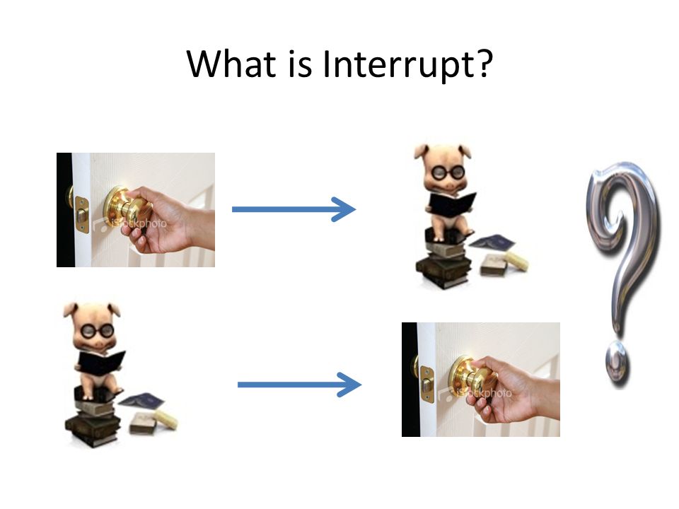
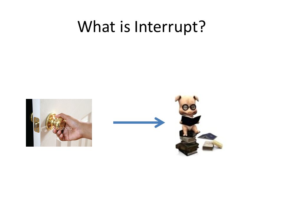
What is Interrupt?

4
What is Interrupt?

7
InterruptReading Remember Open Return to work

8
What is Interrupt? Interrupt Processing Remember current instruction address in Stack Register Execute ISR Return to work In terms of MCU

9
Types of Interrupt External / Hardware InterruptInternal / Software Interrupt Physical or interrupt from outsideADC, TIMER, USART etc.

10
External Interrupt

11
PIC 16F877A has the following 15 interrupt sources : 1)External 2)Timer 0 3)Timer 1 4)RB Port Change 5)Parallel Slave Port Read/Write 6)A/D Converter 7)USART Receive 8)USART Transmit 9)Synchronous Serial Port 10)CCP1 (Capture, Compare, PWM)PWM 11)CCP2 (Capture, Compare, PWM) 12)TMR2 to PR2 Match 13)Comparator 14)EEPROM Write Operation 15)Bus Collision The 5 registers that used to control the operation of Interrupts in PIC 16F877A Microcontroller : 1)INTCON 2)PIE1 3)PIR1 4)PIE2 5)PIR2
External 2)Timer 0 3)Timer 1 4)RB Port Change 5)Parallel Slave Port Read/Write 6)A/D Converter 7)USART Receive 8)USART Transmit 9)Synchronous Serial Port 10)CCP1 (Capture, Compare, PWM)PWM 11)CCP2 (Capture, Compare, PWM) 12)TMR2 to PR2 Match 13)Comparator 14)EEPROM Write Operation 15)Bus Collision The 5 registers that used to control the operation of Interrupts in PIC 16F877A Microcontroller : 1)INTCON 2)PIE1 3)PIR1 4)PIE2 5)PIR2")
12
INTCON Register INTCON Register PIC 16F877A INTCON Register is a readable and writeable register which contains various enable and flag bits for External and Internal Interrupts. GIE – Global Interrupt Enable 1 – Enables all unmasked interrupts 0 – Disables all interrupts PEIE – Peripheral Interrupt Enable 1 – Enables all unmasked peripheral interrupts 0 – Disables all peripheral interrupts

13
TMR0IE – Timer 0 Overflow Interrupt Enable 1 – Enables the TMR0 interrupt 0 – Disables the TMR0 interrupt INTE – RB0/INT External Interrupt Enable 1 – Enables the RB0/INT external interrupt 0 – Disables the RB0/INT external interrupt RBIE – RB Port Change Interrupt Enable 1 – Enables the RB port change interrupt 0 – Disables the RB port change interrupt TMR0IF – Timer 0 Overflow Interrupt Flag 1 – TMR0 register has overflowed. It must be cleared in software. 0 – TMR0 register did not overflow INTF – RB0/INT External Interrupt Flag 1 – The RB0/INT external interrupt occurred. It must be cleared in software. 0 – The RB0/INT external interrupt did not occur

14
RBIF – RB Port Change Interrupt Flag 1 – At least one of the RB7 – RB4 pins changed state, a mismatch condition will continue to set the bit. Reading PORTB will end the mismatch condition and allow the bit to be cleared. It must be cleared in software. 0 – None of the RB7 – RB4 pins have changed state INTEDG bit of OPTION_REG Register is the Interrupt Edge Select bit. When it is 1 interrupt is on rising edge of RB0/INT pin and when it is 0 interrupt is on falling edge of RB0/INT pin.

15
External Interrupt

16
Next Lecture LCD AND KEY BOARD INTERFACING

Similar presentations


.>")


