Download presentation
Presentation is loading. Please wait.

1
Capacitance Physics Montwood High School R. Casao

2
Capacitors and Dielectrics A capacitor is a device that stores electric energy. A capacitor consists of two conductors separated by air, a vacuum or an insulator. Capacitance: depends on the geometry of the capacitor and on the material, called a dielectric, that separates the conductors. A capacitor consists of two conductors (known as plates) carrying charges of equal magnitude but opposite sign.
 carrying charges of equal magnitude but opposite sign..")
3
A potential difference V exists between the conductors due to the presence of the charges.

4
Parallel Plate Capacitor

5
When the switch is closed, the battery establishes an electric field in the wire that causes electrons to move from the left plate into the wire and into the right plate from the wire. As a result, a separation of charge exists on the plates, which represents an increase in electric potential energy of the system of the circuit. This energy in the system has been transformed from chemical energy in the battery.

6
Definition of Capacitance Experiments show the quantity of electric charge Q on a capacitor is linearly proportional to the potential difference between the conductors, that is Q ~ V; mathematically: Q = C · V The capacitance C of a capacitor is the ratio of the magnitude of the charge on either conductor to the magnitude of the potential difference V between them: SI Unit: farad (F), 1F = 1 C/V Commonly used unit is the microfarad, μ F, where 1 μ F = 1 x 10 -6 F C is always positive.
, 1F = 1 C/V Commonly used unit is the microfarad, μ F, where 1 μ F = 1 x F C is always positive.")
7
Parallel - Plate Capacitors A parallel-plate capacitor consists of two parallel conducting plates, each of area A, separated by a distance d. When the capacitor is charged, the plates carry equal amounts of charge. One plate carries positive charge, and the other carries negative charge. The plates are charged by connection to a battery.

8
Parallel-Plate Capacitors Two parallel metallic plates of equal area A separated by a distance d as shown. One plate carries a charge Q and the other carries a charge –Q. A d If the plates are large, charges can distribute themselves over the large area and the amount of charge that can be stored on a plate for a given potential difference increases as the area A is increased.

9
Parallel-Plate Capacitors The capacitance of a parallel plate capacitor is directly proportional to the area of the plates and inversely proportional to the distance between the plates. When air or a vacuum is the dielectric material between the plates: When another material is present as the dielectric material between the plates, the equation includes a dielectric constant k:

10
Parallel-Plate Capacitors ε o is the permittivity of the insulating material (called the dielectric) between the plates. For parallel plate capacitors, the electric field between the plates is: V is the voltage across the plates of the capacitor. d is the distance between the capacitor plates.

11
Capacitors in Parallel When a potential difference V is applied across several capacitors connected in parallel, that potential difference V is applied across each capacitor. The total charge q stored on the capacitors is the sum of the charges stored on all the capacitors. Capacitors connected in parallel can be replaced with an equivalent capacitor that has the same total charge q and the same potential difference V as the actual capacitors. Equivalent capacitor is a single capacitor that has the same capacitance as a combination of capacitors. C eq = C 1 + C 2 + C 3 + …

12
Parallel Combination The individual potential differences across capacitors connected in parallel are all the same and are equal to the potential difference of the voltage source.

13
Parallel Combination When the uncharged capacitors are first connected, electrons transfer between the wires and the plates leaving the left plates positively charged and right plates negatively charged. The energy source for this charge transfer is the internal chemical energy stored in the battery. Flow of charges onto the plates stops when the voltage across the capacitors is equal to that across the battery terminals. Capacitors reach their maximum charge when the flow of charges stops.

14
Parallel Combination The total charge Q stored by the two capacitors: Q = Q 1 + Q 2. The voltage across each capacitor is the same: Q 1 = C 1 · V, Q 2 = C 2 · V Total charge can also be found using: Q = C eq V Equivalent capacitance: C eq · V = C1 · V + C2 · V V cancels and C eq = C 1 + C 2 In general: C eq = C 1 + C 2 + C 3 + …

15
Capacitors in Parallel a b

16
Capacitors in Series When a potential difference V is applied across several capacitors connected in series, the capacitors have identical charge q. The sum of the potential differences across all the capacitors is equal to the applied potential difference V. Capacitors that are connected in series can be replaced with an equivalent capacitor that has the same charge q and the same total potential difference V as the actual series capacitors.

17
Series Combination When a battery is connected to the uncharged capacitors, electrons transfer out of the left plate of C 1 and into the right plate of C 2. As this charge accumulates on the right plate of C 2, an equivalent amount of negative charge is forced off the left plate of C 2 and this left plate therefore has an excess positive charge.

18
Series Combination The negative charge leaving the left plate of C 2 travels through the connecting wire and accumulates on the right plate of C 1. As a result, all right plates end up with a charge –Q and all the left plates end up with a charge +Q. Thus the charges on capacitors connected in series are the same.

19
Series Combination Voltage Δ V across the battery terminals is shared between the two capacitors; Δ V = Δ V 1 + Δ V 2 Equivalent capacitor: C eq = Q/ Δ V For each capacitor, we have Δ V 1 = Q/C 1 and Δ V 2 = Q/C 2 Q/C eq = Q/C 1 + Q/C 2 ; Q’s cancel 1/C eq = 1/C 1 + 1/C 2 In general:

20
Capacitors in Series a b It is easier to use the reciprocal key (x -1 or 1/x) on your calculator: C eq = (C 1 -1 + C 2 -1 + C 3 -1 + …) -1
 on your calculator: C eq = (C C C …) -1")
21
Example: Equivalent Capacitance In parallel use C = C 1 + C 2 In series use 1/C = 1/C 1 + 1/C 2 6.00 F 20.00 F 2.50 F 8.50 F 20.00 F In series use 1/C = 1/C 1 + 1/C 2 5.965 F

22
Example: Equivalent Capacitance In parallel use C = C 1 + C 2 In series use 1/C = 1/C 1 + 1/C 2

23
In series use C C/2 C/3 In parallel use

24
Capacitors with Dielectrics A dielectric is a nonconducting (insulating) material, such as rubber, glass, or waxed paper. When a dielectric is inserted between the plates of a capacitor, the capacitance increases. If the dielectric completely fills the space between the plates, the capacitance increases by a dimensionless factor k, which is called the dielectric constant. Dielectric constant is a property of a material and varies from one material to another.

25
A charged capacitor (a) before and (b) after insertion of a dielectric between the plates. The charge on the plates remains unchanged, but the potential difference decreases from Δ V o to Δ V = Δ V o /k, thus the capacitance increases from C o to k · C o. Note no battery is involved in this example.

26
Capacitors with Dielectrics Capacitance increases by the factor when a dielectric completely fills the region between the plates. If the dielectric is introduced while the potential difference is being maintained constant by a battery, the charge increases to a value Q = · Q o. The additional charge is supplied by the battery and the capacitance again increases by the factor . For a parallel plate capacitor:

27
The surface charges on the dielectric reduce the electric field inside the dielectric. This reduction in the electric field is described by the dielectric constant k, which is the ratio of the field magnitude E 0 without the dielectric to the field magnitude E ind inside the dielectric: The dielectric constant is a measure of the degree of dipole alignment in the material.

29
Properties of Dielectrics Redistribution of charge is called polarization. We assume that the induced charge is directly proportional to the E-field in the material. In dielectrics, induced charges do not exactly compensate charges on the capacitance plates.

30
Effect of a Dielectric on Capacitance Potential difference with a dielectric is less than the potential difference across free space. Results in a higher capacitance. Allows more charge to be stored before breakdown voltage.

31
Dielectric breakdown — the maximum potential difference between the capacitor plates before sparking or discharge. Dielectric strength — the maximum E field between the capacitor plates before the dielectric breaks down and acts as a conductor between the plates (sparks or discharges).
..")
32
Capacitors with Dielectric Material What are the advantages of dielectric material in a capacitor? Increase the capacitance Increase the maximum operating voltage Possible mechanical support between the plates, which allows the plates to be close together without touching, thereby decreasing d and increasing C.

33
Types of Capacitors (a)A tubular capacitor, whose plates are separated by paper and then rolled into a cylinder. (b)A high-voltage capacitor consisting of many parallel plates separated by insulating oil. (c)An electrolytic capacitor.
A high-voltage capacitor consisting of many parallel plates separated by insulating oil. (c)An electrolytic capacitor..")
34
Energy Stored in an Electric Field The work required to bring the total capacitor charge up to a final value Q is W = 0.5 · C · V 2. Work done in charging the capacitor = electric potential energy U stored in the capacitor. This result applies to any capacitors, regardless of its geometry. The potential energy of a charged capacitor may be viewed as being stored in the electric field between its plates.

35
Energy Stored in an Electric Field Electric potential energy stored = amount of work done to charge the capacitor (i.e. to separate charges and place them onto the opposite plates). Capacitor has the ability to hold both charge and energy.
. Capacitor has the ability to hold both charge and energy..")
36
Two Things to Remember About Parallel- Plate Capacitors If the battery remains connected to the parallel-plate capacitor: voltage across the plates remains constant; amount of charge on the plates can change. If the battery is disconnected from the parallel-plate capacitor: voltage across the plates can change if the plate separation changes; amount of charge on the plates remains constant.

37
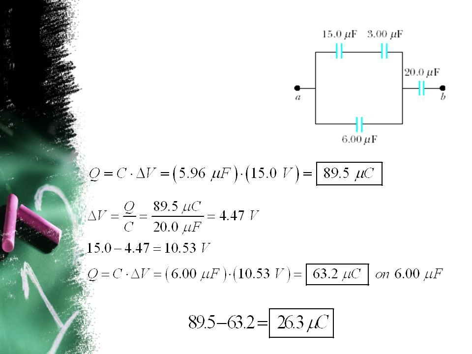
Example Four capacitors are connected as shown. (a)Find the equivalent capacitance between points a and b. (b)Calculate the charge on each capacitor if Δ V ab = 15.0 V.
Find the equivalent capacitance between points a and b. (b)Calculate the charge on each capacitor if Δ V ab = 15.0 V..")
39
Example Find the equivalent capacitance between points a and b for the group of capacitors connected as shown. Take C 1 = 5.00 μ F, C 2 = 10.0 μ F, and C 3 = 2.00 μ F.

Similar presentations


 Potential (energy) What for? positive (+)>")


.>")

