Download presentation
Presentation is loading. Please wait.

1
Multicasting Ju Seong-ho 2002. 05.14

2
Previous work behind main one

3
IGMP Multicast groups are identified by class D IP addresses ( starting with 1110 ) Use “ host membership query ” and “ host membership report ” message to support multicast group membership Queries are sent to all-hosts group ( address 224.0.0.1)
 Use host membership query and host membership report message to support multicast group membership Queries are sent to all-hosts group ( address )")
4
DVMRP Employ RPM(reverse path multicast) to send multicast packets Assign each communication link a metric and threshold to specify link cost and to limit the scope of multicast, respectively Periodically exchange routing table update messages with their neighbors
 to send multicast packets Assign each communication link a metric and threshold to specify link cost and to limit the scope of multicast, respectively Periodically exchange routing table update messages with their neighbors")
5
MOSPF Extend OSPF by adding a new type of LSA, group membership LSA Use IGMP to keep track of group membership information Distribute the information by flooding throughout AS SPT is computed on demand to conserve CPU and memory resource

6
CBT Overcome two shortcomings of DVMRP Costly if NW consists of tens of thousands of nodes, of which only a few are multicast group Should keep track of every (source,group) pair Branches emanate from core router Decrease the size of multicast routing tables at all routers Use JOIN/REQUEST messages
 pair Branches emanate from core router Decrease the size of multicast routing tables at all routers Use JOIN/REQUEST messages")
7
PIM Avoid the overhead of broadcasting packets when group members sparsely populate the Internet Two modes of operation : PIM-SM, PIM-DM PIM-SM ( sparse mode ) employ per-group rendezvous points Use unidirectional shared trees PIM-DM ( dense mode ) employ DVMRP method Used only if data rates exceed a certain value
 employ per-group rendezvous points Use unidirectional shared trees PIM-DM ( dense mode ) employ DVMRP method Used only if data rates exceed a certain value")
8
BGMP Facilitate multicast communication across different ASes Use TCP as its transport protocol Border routers set up a TCP connection between themselves and exchange BGMP messages MIGP component to participate in the MIGP protocol within AS BGMP component to construct a bidirectional center- based tree with other border routers

9
Source Filtering in IP Multicast Routing

10
What is Source Filtering? Specify the reception of packets sent to a multicast group only from a list of source addresses Explicitly identify a list of the sources whose data the host does not want to receive Avoid network bandwidth wastage caused by delivering unnecessary packets to local networks Discussed only in the context of local group management so far

11
Objectives A multicast router will receive a multicast packet from a particular source if and only if at least one host in its directly attached network for from any downstream routers Promptly react to SF state updates Ensure scalability in terms of low overhead in computing and communications Minimize modification to existing multicast routing protocols to support SF

12
SF in Source-Based Trees For DVMRP / PIM-DM A tree is rooted at the flow source and spans all the group members DR just prunes itself from the tree when no one in any directly attached network is interested in packets from a particular source

13
SF in Source-Based Trees (Cont’d) For MOSPF Upon receiving the first multicast packet of a (source,group)pair, the router computes the shortest path tree based on the topology information and the source filtering states Require larger routing table size because each router needs to record the SF states of all other routers in the same OSPF area
 For MOSPF Upon receiving the first multicast packet of a (source,group)pair, the router computes the shortest path tree based on the topology information and the source filtering states Require larger routing table size because each router needs to record the SF states of all other routers in the same OSPF area")
14
SF in Shared Trees Complicated problem Each tree is shared by all sources of the group A source may or may not be a group member Packets may be delivered unidirectionally or bi- directionally Challenge for multicast routing protocols to enable source filtering while achieving scalability

15
Proposed Mechanism Simple and low-overhead source filtering Comprised of two parts Forwarding part Identify SF states stored in each interface Determine to which interfaces a received multicast packet should be forwarded Message exchange part Exchange message to ensure the correctness of the SF tree Minimize network bandwidth wastage

16
First Forwarding Approach Associate each outgoing interface with multiple SF states, each of which records the state of each downstream LAN Unambiguously identify the outgoing interfaces to forward packets upon receiving them Don ’ t scale well because the memory size required by each SF router is proportional to the number of downstream LANs

17
Second Forwarding Approach Associate each outgoing interface with one single SF state which summarizes the requirements of all the downstream LANs Activate outgoing interface when at least one host in any downstream LAN of the interface is interested in receiving source packets Significantly reduce forwarding table size of each router Improve routing efficiency

18
Forwarding Mechanism Each entry in forwarding table stores the SF state information for one interface Each SF state includes a group address, a filter mode, and a source list Activate outgoing interface when Filter mode is “ include ” and the source is in the associated source list Filter mode is “ Exclude ” and the source is not in the associated source list

19
Exchange Message Mechanism Exchange message by flooding in unidirectional shared tree : not scalable Merge the SF states of all outgoing interface belonging to the same group Improve scalability Minimize the overhead Propagate the resultant state upstream to the parent router

20
Exchange Message Mechanism(I) Consider all the interfaces of an SF router m “ include ” filter modes with m source lists ( I 1, I 2, …, I m ) N “ exclude ” filter modes with m source lists ( E 1, E 2, …, E n ) Filter mode M u, source list S u Let I = I 1 ∪ I 2, ∪ … ∪ I m, E = E 1 ∪ E 2 ∪ … ∪ E n If n=0, set M u = include and S u = I ; otherwise, set M u = exclude and S u = E-I
 Consider all the interfaces of an SF router m include filter modes with m source lists ( I 1, I 2, …, I m ) N exclude filter modes with m source lists ( E 1, E 2, …, E n ) Filter mode M u, source list S u Let I = I 1 ∪ I 2, ∪ … ∪ I m, E = E 1 ∪ E 2 ∪ … ∪ E n If n=0, set M u = include and S u = I ; otherwise, set M u = exclude and S u = E-I")
21
Exchange Message Mechanism (Cont’d) Allow hosts to freely change their SF states Require its upstream routers to reflect his change accordingly Merge the table entries of all the other interfaces to generate a new state as soon as an SF state update is received from an interface Forward the new state to its immediate upstream router
 Allow hosts to freely change their SF states Require its upstream routers to reflect his change accordingly Merge the table entries of all the other interfaces to generate a new state as soon as an SF state update is received from an interface Forward the new state to its immediate upstream router")
22
Exchange Message Mechanism (Cont’d) Three drawbacks exist (1) Computational complexity of the merge operation is proportional to the number of interfaces times the size of the source lists of the interfaces (2) New merged state must be propagated upstream, irrespective of whether the new state remains unchanged (3) If new state is slightly different from old state, it is inefficient to perform a merge to all entries and forward the result
 Three drawbacks exist (1) Computational complexity of the merge operation is proportional to the number of interfaces times the size of the source lists of the interfaces (2) New merged state must be propagated upstream, irrespective of whether the new state remains unchanged (3) If new state is slightly different from old state, it is inefficient to perform a merge to all entries and forward the result")
23
Exchange Message Mechanism (Cont’d) Solution for (2) Introduce “ merge ” entry storing merged state Don ’ t forward the resultant state if the merge entry remains unchanged after merging Solution for (3) Use IGMP message : Update, Allow, and Block Update : deliver an entire SF state Allow, Block : no filter mode, source list only
 Solution for (2) Introduce merge entry storing merged state Don ’ t forward the resultant state if the merge entry remains unchanged after merging Solution for (3) Use IGMP message : Update, Allow, and Block Update : deliver an entire SF state Allow, Block : no filter mode, source list only")
24
Exchange Message Mechanism(II) Some notation Before receiving an SF state update Filter mode F mo, source list S mo in merge entry Filter mode F io, source list S io associated with the interface from which the update is received Before receiving an SF state update Filter mode F mn, source list S mn in merge entry Filter mode F in, source list S in associated with the interface from which the update is received
 Some notation Before receiving an SF state update Filter mode F mo, source list S mo in merge entry Filter mode F io, source list S io associated with the interface from which the update is received Before receiving an SF state update Filter mode F mn, source list S mn in merge entry Filter mode F in, source list S in associated with the interface from which the update is received")
25
Exchange Message Mechanism (Cont’d) Upon receiving “ Allow ” message with S a If F io is include, S in = S a ∪ S io If F io is exclude, S in = S io- S a If F mo is include, S mn = S a ∪ S mo, and if S a - S mo ≠ , forward “ Allow ” with S a - S mo toward upstream router If F mo is exclude, S mn = S mo- S a, and if S mo ∩ S a ≠ , forward “ Allow ” with S mo ∩ S a toward upstream router
 Upon receiving Allow message with S a If F io is include, S in = S a ∪ S io If F io is exclude, S in = S io- S a If F mo is include, S mn = S a ∪ S mo, and if S a - S mo ≠ , forward Allow with S a - S mo toward upstream router If F mo is exclude, S mn = S mo- S a, and if S mo ∩ S a ≠ , forward Allow with S mo ∩ S a toward upstream router")
26
Exchange Message Mechanism (Cont’d) Upon receiving “ Allow ” message with S b If F io is include, S in = S io - S b If F io is exclude, S in = S io ∪ S b If F mo is include, and check if any other interfaces are interested in source list S mo ∪ S b If none exists, S mo = S mo -(S mo ∪ S b ) and then forward “ Block ” with source list S mo ∪ S b If F mo is exclude, and check if any other interfaces are interested in source list S b -S mo If none exists, S mn = S mo ∪ S b -S mo and then forward “ Block ” with source list S b -S mo
 Upon receiving Allow message with S b If F io is include, S in = S io - S b If F io is exclude, S in = S io ∪ S b If F mo is include, and check if any other interfaces are interested in source list S mo ∪ S b If none exists, S mo = S mo -(S mo ∪ S b ) and then forward Block with source list S mo ∪ S b If F mo is exclude, and check if any other interfaces are interested in source list S b -S mo If none exists, S mn = S mo ∪ S b -S mo and then forward Block with source list S b -S mo")
27
Exchange Message Mechanism (Cont’d) Upon receiving a change to the SF state or receiving “ Update ” with filter mode F u and source list S u If F u and F io are include, regard it as “ Allow ” with S u - S io and “ Block ” with S io - S u If F u and F io are exclude, regard it as “ Allow ” with S io - S u and “ Block ” with S u -S io If F u and F io are exclude and include respectively, set F in =exclude and S in = S u If F mo is include, check if any other interfaces are
 Upon receiving a change to the SF state or receiving Update with filter mode F u and source list S u If F u and F io are include, regard it as Allow with S u - S io and Block with S io - S u If F u and F io are exclude, regard it as Allow with S io - S u and Block with S u -S io If F u and F io are exclude and include respectively, set F in =exclude and S in = S u If F mo is include, check if any other interfaces are")
28
Exchange Message Mechanism (Cont’d) interested in source list S u ∩S io If none exists, set F in =exclude and S mn = (S u -S mo ) ∪ (S u ∩S io ), then forward “ Update ” with F mn and S mn If F mo is exclude, check if any other interfaces are interested in source list S u ∩ S io If none exists, set F in =exclude and S mn = (S u ∩S mo ) ∪ (S u ∩S io ), then forward “ Update ” with F mn and S mn
 interested in source list S u ∩S io If none exists, set F in =exclude and S mn = (S u -S mo ) ∪ (S u ∩S io ), then forward Update with F mn and S mn If F mo is exclude, check if any other interfaces are interested in source list S u ∩ S io If none exists, set F in =exclude and S mn = (S u ∩S mo ) ∪ (S u ∩S io ), then forward Update with F mn and S mn")
29
Exchange Message Mechanism (Cont’d) If F u and F io are include and exclude respectively, set F in =include and S in = S u, then merge SF states of all interfaces to update merge entry Forward update message to upstream router with F mn and S mn dif Receiving a join or leave message Regard it as update message Join message : F io =include and S io = ‘ empty ’ Leave message : F u =include and S u = ‘ empty ’
 If F u and F io are include and exclude respectively, set F in =include and S in = S u, then merge SF states of all interfaces to update merge entry Forward update message to upstream router with F mn and S mn dif Receiving a join or leave message Regard it as update message Join message : F io =include and S io = ‘ empty ’ Leave message : F u =include and S u = ‘ empty ’")
30
Scalability of SF in IP Multicasting A forwarding table in an SF router should be small - Reduce memory size ( cost ) - Make forwarding efficiency - Support more multicast group Communication and computational overhead should be as small as possible - applicable even for a sizeable network
 - Make forwarding efficiency - Support more multicast group Communication and computational overhead should be as small as possible - applicable even for a sizeable network")
31
For Source-Based Trees In source-based tree, a tree is constructed for each (source,group) pair Adopting DVMRP or PIM-DM Memory size of a router Communication overhead of the entire network
 pair Adopting DVMRP or PIM-DM Memory size of a router Communication overhead of the entire network")
32
For Source-Based Trees (Cont’d) Adopting MOSPF Memory size required by each router Communication overhead of the entire network
 Adopting MOSPF Memory size required by each router Communication overhead of the entire network")
33
For Shared Trees In shared tree, a tree is shared by all sources of the group Required memory size Generated communication overhead

34
Simulation Results Unidirectional shared tree Bi-directional shared tree

35
Simulation Results (Cont’d)
")
36
Conclusion Propose a new mechanism to support the capability of source filtering in IP multicast routing protocols As compared with non-SF multicasting, better bandwidth utilization and scalability in terms of control overhead and forwarding table size Efficient use of resources for IP multicasting

37
Making Qos Aware Multicast Scalable in Terms of Link State Advertisement

38
Qos Aware Multicast Procedures Qos aware multicast tree construction and resource reservation Qos aware forwarding Multicast datagrams of a multicast group will be forwarded along with the Qos aware multicast tree for this traffic Link state advertisement and Qos routing information update Routing information including network topology and available bandwidth of links

39
Previous Works’ foci First two procedures in the front page Not consider scalability of link state advertisement Large number of messages for link state advertisement will be exchanged over the world every time a new Qos aware multicast tree is constructed

40
Proposed Protocol Advertisement of information on links within a domain is limited within that domain Only link state information of inter-domain links is advertised among the border multicast routers Crank back mechanism is used Retry to construct a new Qos aware multicast tree

41
Design Principles Multicast network is divided into domains Intra-domain and inter-domain is introduced Range of link state advertisement exchange is limited for intra-domain and inter-domain levels For the intra-domain multicasting Use PIM-SM as an intra-domain multicast routing protocol and OSPF for intra-domain link state advertisement Use SPT as a Qos aware multicast tree

42
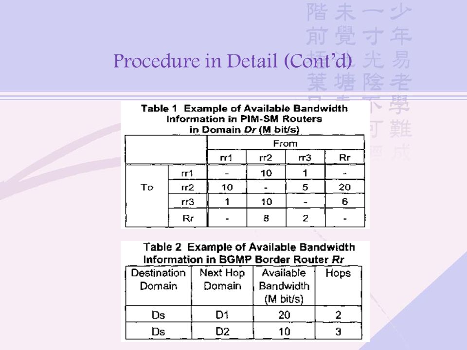
Design Principles (Cont’d) For the inter-domain multicasting Use BGMP as an inter-domain multicast routing protocol and BGP-4 for inter-domain link state advertisement Others are the same as intra-domain When an SPT spreads over multiple domains Use only the information on available bandwidth of links within this domain and inter-domain links The construction will be failed because of no knowledge about other domains
 For the inter-domain multicasting Use BGMP as an inter-domain multicast routing protocol and BGP-4 for inter-domain link state advertisement Others are the same as intra-domain When an SPT spreads over multiple domains Use only the information on available bandwidth of links within this domain and inter-domain links The construction will be failed because of no knowledge about other domains")
43
Design Principles (Cont’d) Crank back mechanism A failure of tree construction is reported back to the original domain of Qos Join message Another trial of SPT construction is performed through different domains Introduce Join NACK message to PIM-SM and BGMP
 Crank back mechanism A failure of tree construction is reported back to the original domain of Qos Join message Another trial of SPT construction is performed through different domains Introduce Join NACK message to PIM-SM and BGMP")
44
Procedure in Detail

45
Procedure in Detail (Cont’d)
")
47
Proposed Message Format For intra-domain, Extend Join message in PIM-SM to assign a new type value for Qos Join message and a new parameter, Required Qos Link Information Add a new parameter for reporting updated available bandwidth in Link State Update message for bandwidth advertisement For inter-domain, Introduce new attributes same as for intra-domain to support the proposed multicast routing protocol

48
Crank Back Mechanism

49
Crank Back Mechanism (Cont’d)
")
50
Simulation

51
Simulation Conditions Evaluate the number of exchanged link state advertisement messages - OSPF Link State Update messages and BGP Update messages Only the leaf routers in a domain initiate a Qos Join attempt All Qos Join messages will succeed All of the links have the same costs - Qos aware multicast tree within a domain is constructed using the shortest path

52
Simulation Conditions (Cont’d) A Qos Join message will be forwarded until the router that has been already receiving the multicast traffic which this Qos Join message is requesting One Link State Update message is used to be delivered to one router When a Qos Join message is sent over an inter-domain link, BGP or IBGP Update message is delivered to each border router in the whole network
 A Qos Join message will be forwarded until the router that has been already receiving the multicast traffic which this Qos Join message is requesting One Link State Update message is used to be delivered to one router When a Qos Join message is sent over an inter-domain link, BGP or IBGP Update message is delivered to each border router in the whole network")
53
Simulation Conditions (Cont’d) One Update message is used to be delivered to one border router Evaluate case of flat network configuration - Exchange OSPF Link State Update messages if the bandwidth of a link is newly reserved Two kinds of simulation environment 1. There is only one sender in the whole network 2. There is one sender in each domain 3. Their locations are selected randomly in both cases

54
First Simulation Results Flat Configuration Configuration with Domains

55
Second Simulation Results Flat Configuration Configuration with Domains

56
Conclusion Multicast network is divided into domains Range of link state advertisement is limited within one domain Among BGMP border multicast routers, only the link state information of inter-domain links is advertised Introduce Crank Back Mechanism in case of tree construction failure Reduce the number of exchanged link state advertisement messages by the order of 1/(number of domains)
")
Similar presentations
 slides are modified from J. Kurose & K. Ross University of Nevada – Reno Computer Science.>")


>")