Download presentation
Presentation is loading. Please wait.

1
Engineering Analysis – 804 441 Computational Fluid Dynamics – 804 416
Umm Al-Qura University Engineering Analysis – Computational Fluid Dynamics – Faculty Name Prof. A. A. Saati

2
Umm Al-Qura University

3
Umm Al-Qura University
Finite Difference Method Parabolic – Elliptic – Hyperbolic Partial Differential Equations CH3

4
Finite Difference Method
Linear Second order PDEs are important sets of equations that are used to model many systems in many different fields of science and engineering. Classification is important because: Each category relates to specific engineering problems. Different approaches are used to solve these categories. Classification in lecture Part 2, Part 3 & Part 4.1show that 2nd Order Linear PDE’s as: Elliptic if Parabolic if Hyperbolic if

5
Finite Difference Method
Parabolic Partial Differential Equations Introductory Remarks Equations of science and engineering such as motion in fluid mechanics are frequently reduced to parabolic formulation Example: Boundary layer equation Parabolized Navier-Stokes (PNS) equation Unsteady heat conduction equation Various finite difference of the model Parabolic Differential Equation (PDE) will be investigated.
 equation. Unsteady heat conduction equation. Various finite difference of the model Parabolic Differential Equation (PDE) will be investigated.")
6
Finite Difference Method
Finite Difference Formulations Consider 1-D 2nd order PDE (unsteady heat conduction equation) The model equation has the following form Various finite difference approximations can be used to represent the derivatives in the equation Let forward finite difference for of order and central finite difference for of order
 The model equation has the following form. Various finite difference approximations can be used to represent the derivatives in the equation. Let forward finite difference for of order. and central finite difference for of order.")
7
Finite Difference Formulations [Explicit Method]
The equation can be approximated by the following difference equation. In this equation, is the only unknown and therefore, it can be computed from the following and the time level n is known form a previous solution or given as initial data. The 2nd -order PDE has been replaced by algebraic equation.
![Finite Difference Formulations [Explicit Method]](http://slideplayer.com/slide/8629045/26/images/7/Finite+Difference+Formulations+%5BExplicit+Method%5D.jpg "The equation can be approximated by the following difference equation. In this equation, is the only unknown and therefore, it can be computed from the following and the time level n is known form a previous solution or given as initial data. The 2nd -order PDE has been replaced by algebraic equation.")
10
Finite Difference Formulations [Implicit Method]
When a first-order backward difference approximation for the time derivative And a second-order central difference approximation for the spatial derivative is used The equation takes the form: There are three unknowns:
![Finite Difference Formulations [Implicit Method]](http://slideplayer.com/slide/8629045/26/images/10/Finite+Difference+Formulations+%5BImplicit+Method%5D.jpg "When a first-order backward difference approximation for the time derivative. And a second-order central difference approximation for the spatial derivative is used. The equation takes the form: There are three unknowns:")
11
Finite Difference Formulations [Implicit Method]
The computation of the unknowns would require a set of coupled finite difference equations The above equation can be rearranged as: A formulation of this type, which includes more than one unknown in each FDE, is known as an implicit method. The equation may expressed in the general form as: This FDE is written for all grid points, resulting in a set of algebraic equations, These equation are put in a matrix form.
![Finite Difference Formulations [Implicit Method]](http://slideplayer.com/slide/8629045/26/images/11/Finite+Difference+Formulations+%5BImplicit+Method%5D.jpg "The computation of the unknowns would require a set of coupled finite difference equations. The above equation can be rearranged as: A formulation of this type, which includes more than one unknown in each FDE, is known as an implicit method. The equation may expressed in the general form as: This FDE is written for all grid points, resulting in a set of algebraic equations, These equation are put in a matrix form.")
12
Finite Difference Method
Explicit Methods This section introduces some of the commonly used explicit methods for solving parabolic equations.

13
The Forward Time/Central space (FTCS) method
This is read truncation error of order The method is stable for

14
The Richardson method In this approximation, central differencing is used for both time and space derivatives. - this is read truncation error of order - The method is unconditionally unstable

15
The DuFort-Frankel method
This method is a modification of the Richardson method - this is read truncation error of order The equation can be solve explicitly for at time level The method is unconditionally stable

16
The grid point involved in the method are shown in the figure.

17
Example - 1 (Explicit Methods)
ice

18
Example - 1 (Explicit Methods)
")
19
Example - 1 (Explicit Methods)
Sin(0.25π) Sin(0. 5π) Sin(0.75π)
 Sin(0. 5π) Sin(0.75π)")
20
Example - 1 (Explicit Methods)
Sin(0.25π) Sin(0. 5π) Sin(0.75π)
 Sin(0. 5π) Sin(0.75π)")
21
Example - 1 (Explicit Methods)
Sin(0.25π) Sin(0. 5π) Sin(0.75π)
 Sin(0. 5π) Sin(0.75π)")
22
Example - 1 (Explicit Methods)
Remarks on Example 1

23
Example - 1 (Explicit Methods)
Sin(0.25π) Sin(0. 5π) Sin(0.75π)
 Sin(0. 5π) Sin(0.75π)")
24
Example - 1 (Explicit Methods)
Sin(0.25π) Sin(0. 5π) Sin(0.75π)
 Sin(0. 5π) Sin(0.75π)")
25
Example - 1 (Explicit Methods)
Sin(0.25π) Sin(0. 5π) Sin(0.75π)
 Sin(0. 5π) Sin(0.75π)")
26
Implicit Methods

27
Implicit Methods When a first-order backward difference approximation for the time derivative And a second-order central difference approximation for the spatial derivative is used The equation takes the form: A formulation of this type, which includes more than one unknown in each FDE, is known as an implicit method.

28
Implicit methods offer great advantage on the stability, since most are unconditionally stable
* A larger step size in time is permitted * An increase in time step will increase the truncation error.

29
The Laasonen Method When a first-order backward difference approximation for the time derivative And a second-order central difference approximation for the spatial derivative is used The equation takes the form: - this is read truncation error of order

30
The Crank-Nicolson method
The diffusion term is replaced by the average of the central differences at time levels n and n+1

31
The left side of the equation is a central difference of step
Which is of order The equation would be of the form - this is read truncation error of order - The method is unconditionally stable

32
In terms of the grid point ( see figure)
the left side can be interpreted as the central difference representation of at point A the right side is the average of the diffusion term at the same point using the explicit method using implicit method Adding this tow equations we obtains

33
The Beta Formulation A general form of the finite difference equation
- The method is unconditionally stable for Note: the formulation is Crank-Nicolson implicit for the formulation is conditionally stable for the formulation is FTCS explicit for

34
Example - 2 (Implicit Methods)
")
35
Example - 2 (Implicit Methods)
")
36
Example - 2 (Implicit Methods)
")
37
Example - 2 (Implicit Methods)
u1, u2, u3,1 t0=0 t1=0.25 t2=0.5 t3=0.75 t4=1.0 x1=0.25 x2=0.5 x0=0.0 x3=0.75 x4=1.0 Sin(0.25π) Sin(0. 5π) Sin(0.75π) u1, u2, u3,4 u1, u2, u3,3 u1, u2, u3,2
 Sin(0. 5π) Sin(0.75π) u1,4 u2,4 u3,4. u1,3 u2,3 u3,3. u1,2 u2,2 u3,2.")
38
Example - 2 (Implicit Methods)
Solution of Row 1 at t1=0.25 sec

39
Example - 2 (Implicit Methods)
Solution of Row 2 at t2=0.5 sec u1, u2, u3,1 t0=0 t1=0.25 t2=0.5 t3=0.75 t4=1.0 x1=0.25 x2=0.5 x0=0.0 x3=0.75 x4=1.0 Sin(0.25π) Sin(0. 5π) Sin(0.75π) u1, u2, u3,4 u1, u2, u3,3 u1, u2, u3,2
 Sin(0. 5π) Sin(0.75π) u1,4 u2,4 u3,4. u1,3 u2,3 u3,3. u1,2 u2,2 u3,2.")
40
Example - 2 (Implicit Methods)
Solution of Row 3 at t3=0.75 sec

41
Example - 2 (Implicit Methods)
Solution of Row 4 at t4=1 sec

42
Remarks The Explicit Method:
One needs to select small time step to ensure stability. Computation per point is very simple but many points are needed. Implicit Nicolson: Requires the solution of a Tri-diagonal system. Stable (Larger time step can be used).
.")
43
Applications - 1 Various finite difference equations were used to represent the parabolic model equation It is important to write computer codes and analyzing the results which give additional insights into the solution procedures are gained

44
Example Consider a fluid bounded by two parallel plates extended to infinity such that no end effects are encountered. The planar walls and the fluid are initially at rest. The lower wall is suddenly accelerated in the x-direction the Navier-Stokes equations for this problem may be expressed as.

45
- The fluid is oil with a kinematic viscosity of
- The spacing h = 40 mm. - The velocity of the lower wall - It is required to compute the velocity profile - A solution for the velocity is to be obtained up to 1.08 seconds

46
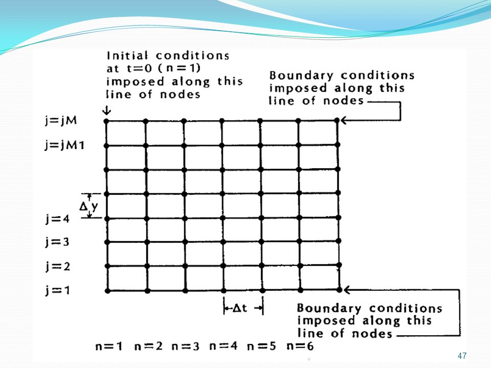
The initial and boundary conditions for this problem are stated as
Initial condition Boundary conditions Let assume various of time step is to be used to investigate the numerical schemes and the effect of time step on the stability.

48
Solve the above example with the following methods
The FTCS explicit method with The DuFort-Frankel explicit method with The Laasonen implicit method with The Crank-Nicolson method with

49
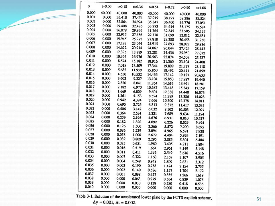
Solution Case 1.I the FTCS explicit method is to be used
the stability require the term is known as diffusion number for this case the diffusion number is therefore the stability condition is satisfied

52
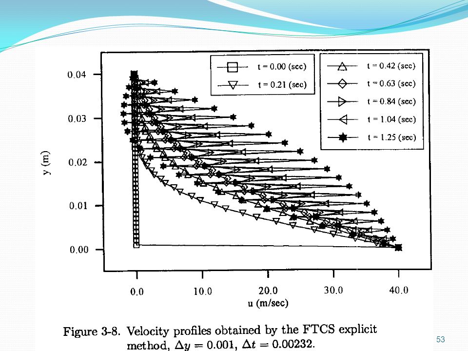
Case 1.II the FTCS explicit method is to be used for this case the diffusion number is therefore the stability condition is not satisfied

54
Analysis In the earlier section, various finite difference formulation were applied to the PDE and ODE The effect of the stability imposed by the diffusion number on the FTCS explicit method This method the step sizes is limited due to the stability The implicit methods are unconditionally stable and allow larger time steps. But the accuracy requirement limits the use of large time step (increase the time step will increase the truncation errors)
")
55
For the simple problem, an analytical solution may be obtained
Analysis For the simple problem, an analytical solution may be obtained This analytical result is used for: Code validation. Comparison of various methods Study the effect of step size on the accuracy of the solution An error term is defined as: A comparison of various methods.

56
Analysis Comparison of error distribution for various schemes at t=0.18 using the following error term:

57
Analysis Comparison of error distribution for various schemes at t=1.08 using the following error term:

58
Analysis Comparison of error distribution for different time steps by using Lassonen method at t = 1.0 sec.

59
Parabolic Equations in Two-Dimension
Various finite difference formulations of parabolic PDEs have been discussed for 1-D The space dimension is extended to two An efficient method of solution is presented. Consider the model equation. Where is considered to be constant.

60
Parabolic Equations in Two-Dimension
Consider an explicit formulation. By using forward differencing for the time derivative and central differencing for the space derivatives. This is read truncation error of order The method is stable for Define the diffusion numbers The stability requirement is expressed as

61
Parabolic Equations in Two-Dimension
Consider an implicit formulation. By using backward differencing for the time derivative and central differencing for the space derivatives. By defining the coefficients of the unknowns as a, b, c, d and e and the right hand side by f, the equation may be written as

62
Parabolic Equations in Two-Dimension
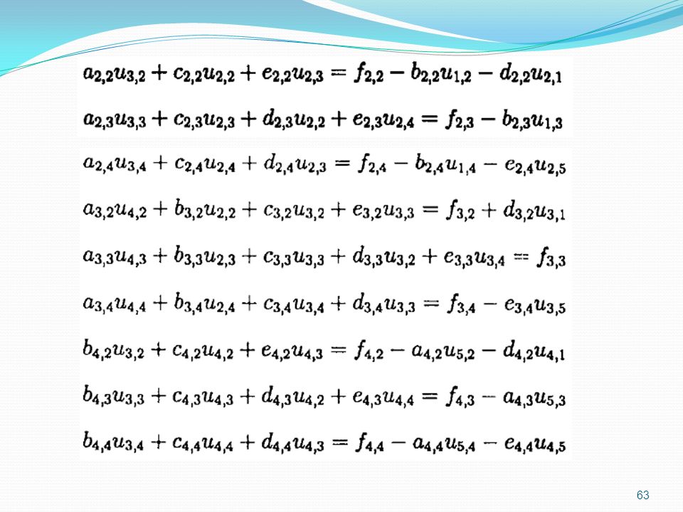
Consider the 5 by 5 grid system as shown in the Figure There are nine unknown at time level n+1 A total of nine simultaneous equations must be solved. The implicit finite difference equations for the grid system are

64
The known quantities from the imposed boundary conditions have been moved to the right side and added to the known quantities from the previous n time level. The set of equations can be written in a matrix form as.

65
The coefficient matrix is pent-diagonal.
The solution procedure for this matrix is very time consuming. One way to overcome the time consuming is by using a splitting method. This method is known as alternating direction implicit method ADI. The algorithm produces two sets of tri-diagonal simultaneous equations to be solved in sequence. The finite difference equations of the model in ADI formulation are

66
ADI method - The method is of order
- The method is unconditionally stable

67
The method can be written in the tri-diagonal form as:

68
ADI method solution procedure
Start the solution with the first equation, the formulation is implicit in the x-direction and explicit in the y-direction; the solution at this stage is referred to as the x sweep. Then the solution with the second equation, the formulation is implicit in the y-direction and explicit in the x-direction; the solution at this stage is referred to as the y sweep. Graphical presentation of the method is shown in the following Figure.

70
Application - 2

71
Application - 2 Consider the 2-D heat conduction equation
Where the thermal diffusivity It is required to determine the temperature distribution in a long bar with a rectangular cross-section. Assume the bar is composed of chrome steel, which has cross sectional dimensions of 3.5 ft by 3.5 ft (b=h=3.5) Initial condition t = 0 Boundary condition
 Initial condition t = 0. Boundary condition.")
72
Application - 2 The rectangular plate with B.C.

73
Application - 2 Application of the ADI method: FDE for x-sweep
By defining the coefficients for the tri-diagonal system as:

74
Application - 2 Application of the ADI method:
Note that in order to rearrange the equations as tridiagonal system C(I,4) must be modified at i = 2 & i = IM-1. At I = 2 At I = IM-1 = IMM1 Since are known from the boundary conditions and constant
 must be modified at i = 2 & i = IM-1. At I = 2. At I = IM-1 = IMM1. Since are known from the boundary conditions and constant.")
75
Application - 2 Application of the ADI method: FDE for y-sweep
By defining the coefficients for the tri-diagonal system as:

76
Application - 2 Application of the ADI method:
Note that in order to rearrange the equations as tridiagonal system C(I,4) must be modified at J = 2 & J = JM-J. At J = 2 At J = JM-1 = JMM1 Since are known from the boundary conditions and constant 76
 must be modified at J = 2 & J = JM-J. At J = 2. At J = JM-1 = JMM1. Since are known from the boundary conditions and constant. 76.")
77
Application - 2 Application of the ADI method:
Tri-diagonal matrix can be solved by using the Gaussian elimination method According to Gaussian elimination method, we multiply the second equation by and the first by and then take the difference of the two to eliminate The resulting equation is If we replace the following 77

78
Application - 2 Application of the ADI method:
The same process is repeated for i = 3, 4, ….., n-1 Where I = 2,3,4,………,n and n = IM-2 or JM-2 The value of can immediately be found by solving simultaneously the last two equations 78

79
Application - 2 Application of the ADI method:
The remaining unknowns can be calculated in a backward order the following formula j = n-1, n-2, n-3, ………, 2, 1 79

80
Application - 2 Initial temperature distribution.
Temperature distribution at t = 0.1 hr. Temperature distribution at t = 0.4 hr. See pages ( ) 80
 80.")
81
Sections 3.8 …….. 3.13 for advance courses
Approximate Factorization Fractional Step Methods 3.10 Extension to Three-Space Dimensions 3.11 Consistency Analysis of Finite Difference Equations 3.12 Linearization 3.13 Irregular Boundaries

82
Parabolic Partial Differential Equations
END OF Parabolic Partial Differential Equations

Similar presentations


 Different from the finite difference method (FDM) described earlier, the FEM introduces approximated solutions of the variables.>")


 K. M. Isaac Professor of Aerospace Engineering.>")


:>")


 Lectures 37-39 KFUPM (Term 101) Section 04 Read 29.1-29.2 & 30.1-30.4 CISE301_Topic9.>")
 Lectures 37-39 KFUPM Read 29.1-29.2 & 30.1-30.4 CISE301_Topic9 KFUPM.>")

