Download presentation
Presentation is loading. Please wait.

1
Development of a Gamma-Ray Beam Profile Monitor for the High-Intensity Gamma-Ray Source Thomas Regier, Department of Physics and Engineering Physics University of Saskatchewan

2
Beam Profile Monitor Component of Beam Diagnostic System Provides Gamma-Ray Position and Flux Information Assists users and operators in experiment and beam configuration

3
The High Intensity Gamma-Ray Source

4
270 MeV Linear Accelerator Electron Source Electron Storage Ring OK-5 Free Electron Laser RF Booster Experimental Area

5
Design Requirements Sub-millimeter resolution Easy to use Non-destructive Handle beam energies between 2 and 225 MeV Handle beam fluxes between 10 5 and 10 10 gammas per second

6
Detecting Gamma-Rays

7
Design Concept Gamma-Rays interact with the scintillator, generating flourescent illumination. The illuminated scintillator is imaged onto a Charge Coupled Device by a lens system. The CCD records the illumination pattern by converting the incident photons into electrons

8
System Model NCNC Relates the number of counts registered by the CCD camera to the power absorbed by the scintillator and the length of the exposure through the responsivity of the system. R SYS P absorbed t INT = int[ ]

9
CCD Noise

10
Design Light Tight Box CCD Camera Lens System Scintillator Inrun / Outrun Windows

11
CCD Camera Starlight Express MX-5 Sony ICX055BL CCD Chip Single Stage Thermoelectric Cooler (Room Temp – 30 o C) External USB Controller Capable of ‘binning’ Linux Based Data Acquisition 3 rd Party USB drivers Custom camera control software
 External USB Controller Capable of ‘binning’ Linux Based Data Acquisition 3 rd Party USB drivers Custom camera control software")
12
Optics -Had to balance… - Overall length - Number of lenses - Aperture - Magnification

13
Source Testing - Used 23 mCi 137 Cs source to test system response - Testing resulted in a series of improvements to apparatus

14
137 Cs Emission Spectrum

16
Data Analysis/Processing Original Image of 137 Cs Source Radiation Background Subtracted Image Image processed to remove bad pixels

17
Calibration -Performed to find the system responsivity, R SYS -Combines… - Source profile measurement data - Source flux measurement data - Geant simulation results -Provides a link between the image intensity and the gamma-ray flux Source Flux Measurement Geant Simulation Source Profile Data

18
-Determined by the number of counts in a particular region of the image, divided by the amount of energy deposited in the corresponding region on the scintillator R SYS = N C / (P absorbed t INT ) = 126 Counts per GeV Source Flux Measurement with NaI Detector and Geant Simulation Results
 = 126 Counts per GeV Source Flux Measurement with NaI Detector and Geant Simulation Results")
19
Predicted Exposure Times -Dictated by the signal to noise ratio -Calculated by examining an individual camera “bin” Portion of the signal generated by something other than the incident illumination Portion of the output signal generated due to exposure to illumination n full r sys P absorbed t INT n T = + i dark t INT + n floor

20
Predicted Exposure Times n T = r sys P absorbed t INT + i dark t INT + n floor n B = i dark t INT + n floor n S = n T – n D = r sys P absorbed t INT δn S 2 = δn T 2 + δn B 2 Background Subtraction is performed to find signal

21
Predicted Exposure Times -Select a fraction of error, ε, that gives εn S (t INT ) = δn S (t INT ) -Find a solution for t INT that satisfies this relationship
 = δn S (t INT ) -Find a solution for t INT that satisfies this relationship")
22
A Plot of the Time Required to Obtain a Fraction of Error, ε, for P absorbed Values of 20, 60 and 100 GeV/s ε

23
The Time Required to Achieve 5% Error Per Pixel Versus Beam Energy For Various Scintillator-Converter Configurations

24
Conclusions - The combination of a scintillator, lens system, and CCD camera can be used to measure the profile of a gamma- ray source - Submillimeter resolutions are achievable - The method is non-destructive - Predicted exposure times for a nominal beam flux are less than a minute

25
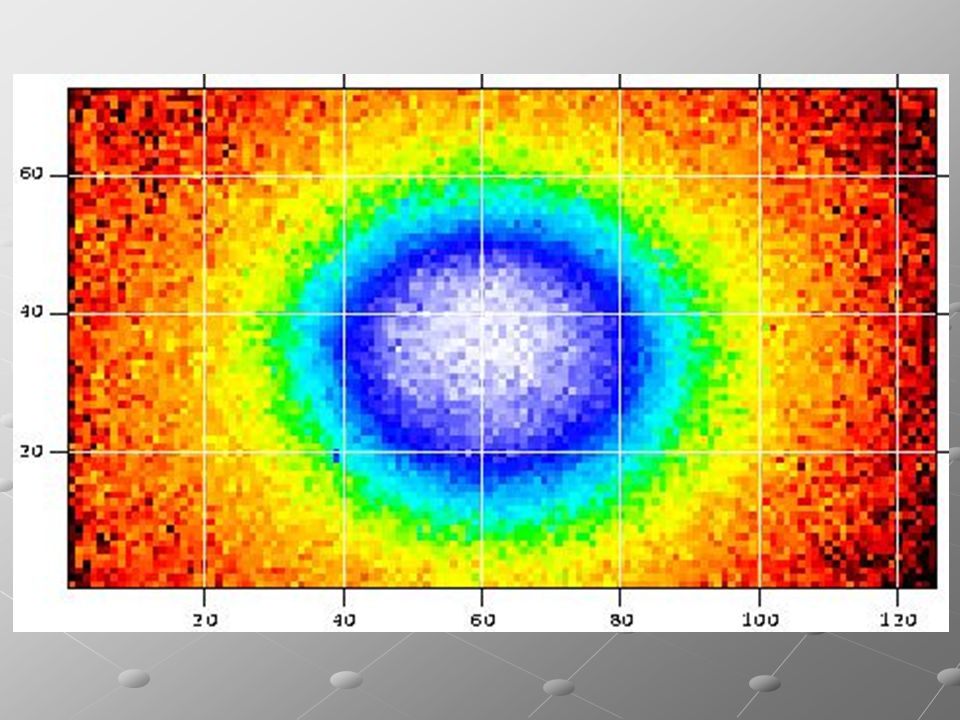
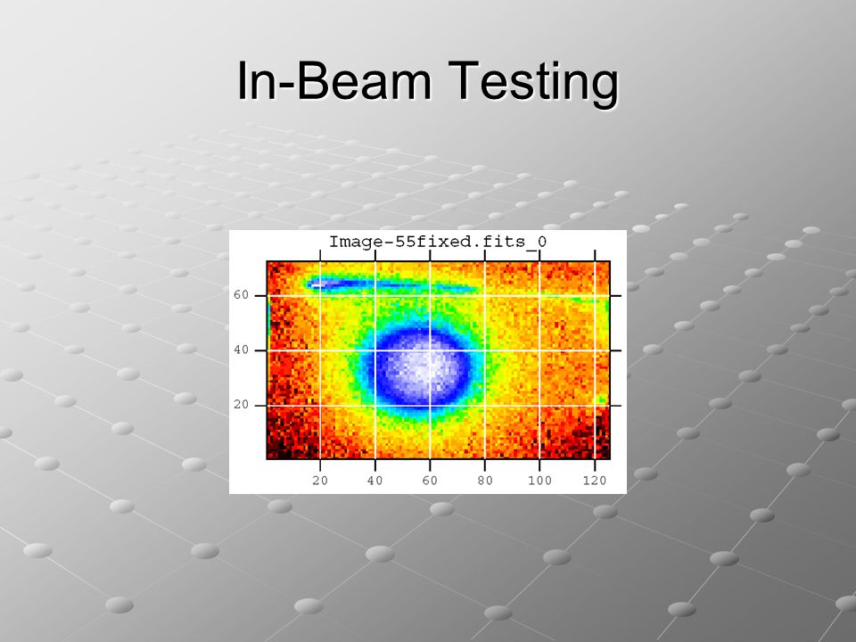
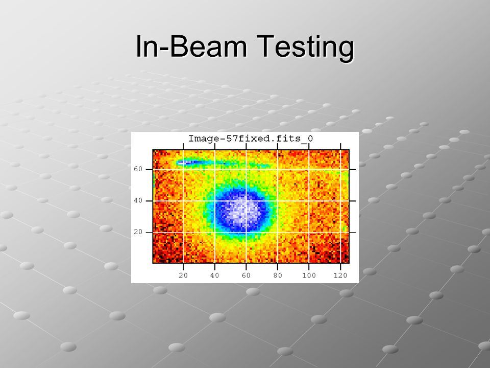
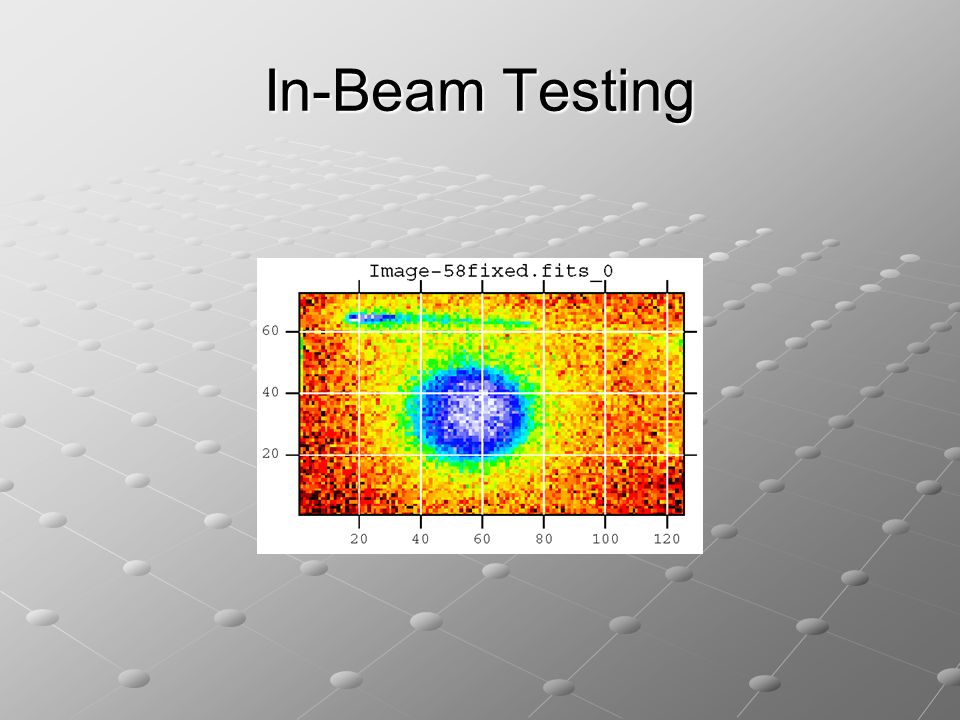
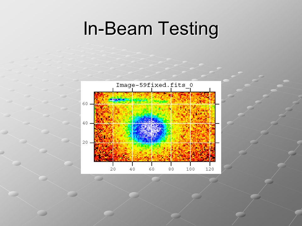
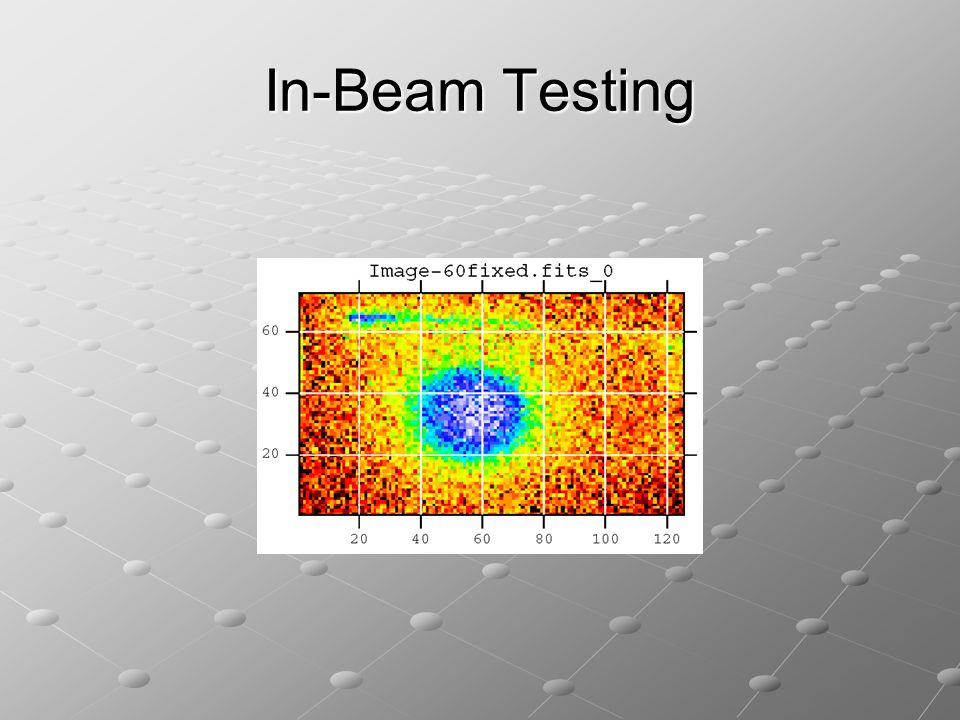
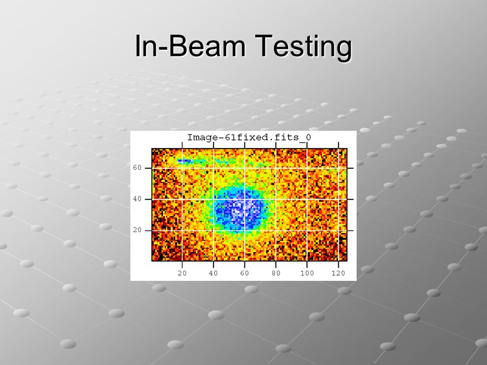
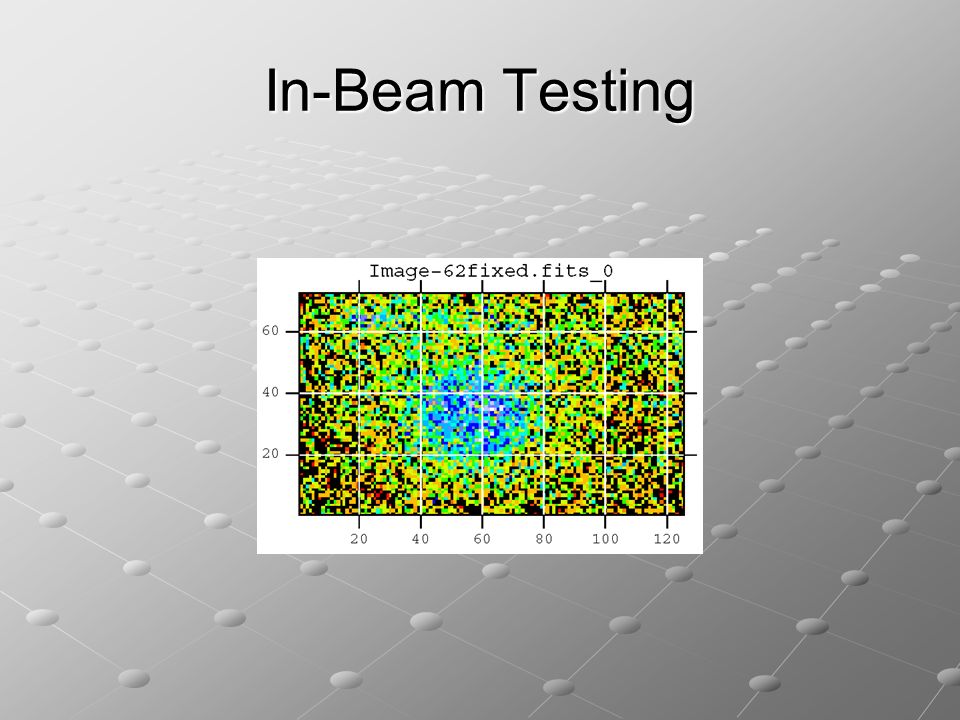
In-Beam Testing

Similar presentations


>")


