Download presentation
Presentation is loading. Please wait.

2
Basics of Networking Laboratory Lecture no. 1

3
Basics of Networking Historical Background Networking began its infancy in the mid -1960’s. by the US Department of Defence (DoD). The original intention of networking was being developed to withstand a nuclear war. Telephone networks were to vulnerable and would terminate all conversations should a nuclear war occur.
. The original intention of networking was being developed to withstand a nuclear war. Telephone networks were to vulnerable and would terminate all conversations should a nuclear war occur..")
4
ARPA (Advanced Research Projects Agency) was created in response with the launching of the Sputnik in 1957. ARPA decided that a DoD network should be packet- switched networked consisting of a subnet and host computers. Experimental network research was awarded to UCLA, UCSB, SRI and Univ. of Utha in 1969. These areas were because they all had a large number of ARPA contracts. Basics of Networking

5
These 4 universities also had different and completely incompatible host computers. ARPANET protocols were not suitable for running over multiple networks, so TCP/IP model and protocols were invented in 1974. ARPA awarded several other contracts and specifically Univ.. of California at Berkeley to integrate the protocols with the Berkeley UNIX. Basics of Networking

6
Berkeley developed a convenient program interface to the network and wrote many applications, utility, and management programs to make networking easier. In it early infancy, the OSI protocols were crushed and the TCP/IP protocols were already in widespread use. The OSI Model had seven layers because at the time, IBM had a propriety seven -layer protocol called SNA (Systems Network Architecture). Basics of Networking
. Basics of Networking.")
7
At the time, IBM dominated the computer companies and every was scared to death that IBM would use its clout to force everyone to use SNA. The OSI was to be produced like an IBM-reference model. The OSI model became the world standard and was not controlled by one company, but by a neutral organization, ISO (International Standards Association). Basics of Networking
. Basics of Networking.")
8
TYPES OF NETWORKS LAN – LOCAL AREA NETWORK IS A SMALL GEOGRAPHICAL AREA SUCH AS OUR SCHOOL BOARD. MAN – METROPOLITAN AREA NETWORK IS A NETWORK OVER A LARGER GEOGRAPHICAL AREA SUCH AS THE PROVINCIAL GOVERNMENT. WAN – WIDE AREA NETWORK IS A NETWORK USED OVER AN EXTREMELY LARGE GEOGRAPHICAL AREA SUCH AS THE FEDERAL GOVERNMENT. Basics of Networking

9
NETWORKS ARE BROKEN INTO 3 TOPOLOGIES. THEY ARE: BUS TOPOLOGY STAR TOPOLOGY RING TOPOLOGY Basics of Networking

10
BUS TOPOLOGY ALLOWS INFORMATION TO BE DIRECTED FROM ONE COMPUTER TO THE OTHER. LOTS OF BINARY COLLISION THOUGH. Basics of Networking

11
STAR TOPOLOGY IS THE MOST COMMON TYPE USED. ALL COMPUTERS ARE ATTACHED TO A HUB. LESS COLLISIONS AND MOST EFFICIENT. Basics of Networking

12
RING TOPOLOGY- USES A TOKEN TO PASS INFORMATION FROM 1 COMPUTER TO THE OTHER. A TOKEN IS ATTACHED TO THE MESSAGE BY THE SENDER TO IDENTIFY WHICH COMPUTER SHOULD RECEIVE THE MESSAGE. AS THE MESSAGE MOVES AROUND THE RING, EACH COMPUTER EXAMINES THE TOKEN. IF THE COMPUTER IDENTIFIES THE TOKEN AS ITS OWN, THEN IT WILL PROCESS THE INFORMATION. Basics of Networking

14
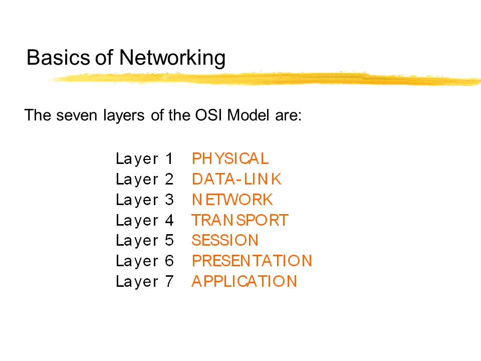
The seven layers of the OSI Model are: Basics of Networking

16
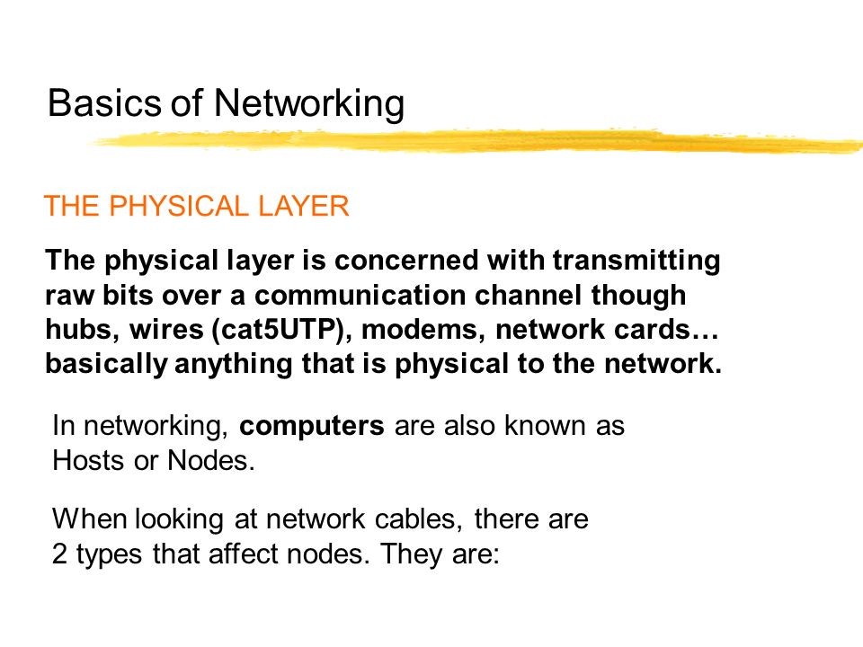
THE PHYSICAL LAYER The physical layer is concerned with transmitting raw bits over a communication channel though hubs, wires (cat5UTP), modems, network cards… basically anything that is physical to the network. When looking at network cables, there are 2 types that affect nodes. They are: In networking, computers are also known as Hosts or Nodes. Basics of Networking

17
Straight though cables or also known as patch cables Cross-over cables Basics of Networking

18
Wiring: 1-3 White/Orange 2-6 Orange 3-1 White/Green 6-2 Green 4-4 Blue 5-5 White/Blue 7-7 White/Brown 8-8 Brown Typical Crossover Cable Basics of Networking

19
TWISTED SHIELDED PAIR – USED IN PHONE LINES UNSHIELDED TWISTED PAIR – USED IN NETWORK COAXIAL CABLE – USED IN CABLEVISION GREAT FOR VIDEO FIBRE OPTIC CABLES - USES LIGHT TO CARRY SIGNAL BUT HARD TO WORK WITH AND LOOSES SIGNAL OVER LONGER DISTANCES COMMUNICATION CHANNELS Basics of Networking

20
Crimping Tool Hub Basics of Networking

21
THE DATA-LINK LAYER The data link layer takes raw transmission and transform it into a line that appears free of transmission errors in the network layer. The Data-Link Layer also is where you would find the MAC Address. (Media Access Control). To find the MAC Address of your computer, or any computer: Start/Programs/MS Prompt and type: ipconfig/all Basics of Networking "C:\WINDOWS>" prompt, type "tracert www.howstuffworks.com"
. To find the MAC Address of your computer, or any computer: Start/Programs/MS Prompt and type: ipconfig/all Basics of Networking C:\WINDOWS> prompt, type tracert .")
22
THE DATA-LINK LAYER You will also find smart devices such as switches in the Data-Link Layer. The digital information that needs to be sent such as and e-mail, attachments, etc needs to be broken into smaller bits known as packets. These packets require some information similar to sending a letter in the mail. Basics of Networking

23
THERE ARE A NUMBER OF PACKETS THAT WILL FOLLOW EACH OTHER TO THE FINAL DESTINATION. Basics of Networking

24
THE NETWORK LAYER The network layer is concerned with controlling the operation of the subnet. A ROUTER is used to determining how packets are routed from source to destination. If one path is busy, then the router will select another path for the packets to travel. So really, the packets can all have different paths and find their way to the final destination. Basics of Networking

25
THE NETWORK LAYER The router has millions of IP addressing built into the software, and knows where to send the packets. IP stands for Internet Protocol and is basically an address that the packets will be sent to. An example would be 216.27.61.137 Basics of Networking

26
THE NETWORK LAYER If you look at the IP Address, the number are broken into different categories. 216. 27.61.137 ClassificationHosts 216. 27.61.137 Octets Basics of Networking

27
Classifications can be broken into 3 classes. They are: Class A - Only the first octet is used for addressing and the balance used for hosts. Class B - The first two octet are used for addressing and the balance used for hosts. Class C - The first three octet are used for addressing and the balance used for hosts. Basics of Networking

28
Every machine on the Internet has a unique identifying number, called an IP Address. A typical IP address looks like this: 216.27.61.137 But computers communicate in binary form. Basics of Networking

29
The same IP address in binary: 11011000.00011011.00111101.10001001 216.27.61.137 Basics of Networking

30
If you add all the positions together, you get 32, which is why IP addresses are considered 32-bit numbers Combine the four octets and you get 2 32 or a possible 4,294,967,296 unique values. 11011000.00011011.00111101.10001001 Basics of Networking

31
Class A - This class is for very large networks, such as a major international company might have. IP addresses with a first octet from 1 to 126 are part of this class. Basics of Networking

32
Class B - This class is used for medium-sized networks. A good example is a large college campus. IP addresses with a first octet from 128 to 191 are part of this class. Class B addresses also include the second octet as part of the Net identifier. Basics of Networking

33
Class C - Class C addresses are commonly used for small to mid-size businesses. IP addresses with a first octet from 192 to 223 are part of this class. Class C addresses also include the second and third octets as part of the Net identifier. Basics of Networking

34
Loopback - The IP address 127.0.0.1 is used as the loopback address. This means that it is used by the host computer to send a message back to itself. Basics of Networking LOOPBACK

35
THE TRANSPORT LAYER The transport layer “DIRECTS PACKETS”, splits it up into smaller units if need be, pass these to the network and ensure that the pieces are travelling in an orderly fashion. A series of protocols are also established in this layer to ensure proper flow of the packets. You can basically describe the Transport Layer as a “TRAFFIC COP”. Basics of Networking

36
THE SESSION LAYER The session layer allows different machines to establish sessions between themselves. Once communications are established, encryption then begins both parties. Basics of Networking

37
THE PRESENTATION LAYER The Presentation Layer’s job is managing data structures and converting from the representation used inside the computer to the network standard representation an visa versa. Basically it takes the packets and re-assembles them so you can open the e-mail or the attachment. If any packets got lost along the way, or were damaged, then the Presentation layer will send a sign to the sender that it requires the specific packet. Basics of Networking

38
THE APPLICATION LAYER The Application layer contains a variety of protocols that are commonly required. Another Application layer function is file transfer. Different file systems have different file naming conventions, different ways of representing text lines, and so on. Transferring a file between two different systems requires handling and other incompatibilities. Basics of Networking

39
THE APPLICATION LAYER Basics of Networking

40
THE APPLICATION LAYER Basics of Networking

41
RESOURCES http://compnetworking.about.com/library/glossary/bldef-bandwidth.htm www.3com.com/other/pdfs/infra/ corpinfo/en_US/501302.pdf - IP Addressing http://computer.howstuffworks.com/question549.htm Networks, Interfaces and Integrated Circuits ( Graham Smyth and Christine Stephenson) www.cisco.com
")
Similar presentations


 Ist Year Ist Sem. T h i s p r e s e n t a t i o n w i l l p r o b a b l y i n v o l v e a u d i e n c e d.>")


. Introduction Overview of the basic concepts of networking Also discusses essential topics of networking theory.>")


>")


