Download presentation
Presentation is loading. Please wait.

1
Microcontrollers Module 3: Digital Display

2
7 – Segment Display A seven-segment display (SSD), or seven- segment indicator, is a form of electronic display device for displaying decimal numerals. display devicedecimal numerals Seven-segment displays are widely used in digital clocks, electronic meters, and other electronic devices for displaying numerical information. digital clocks

5
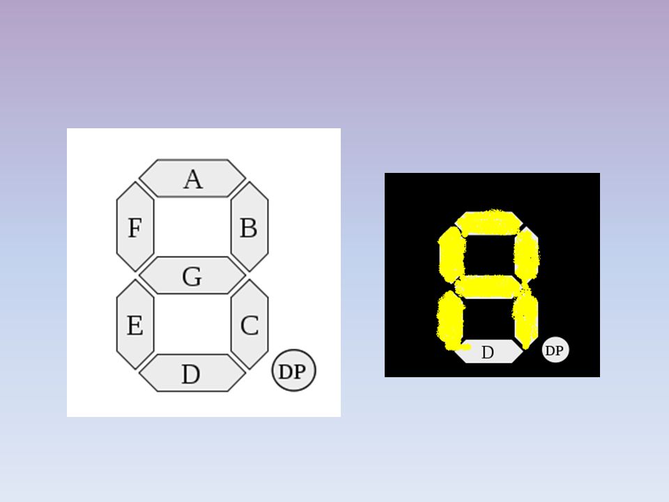
DECIMAL POINT Each of the segments A through G contains an LED that can be controlled individually

6
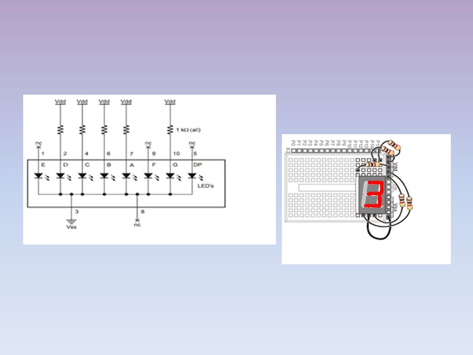
7-Segment LED Display Part Drawing and Pin Map Pin NoMapping 1Controls segment E 2Controls segment D 3 & 8Common Cathode 4Controls segment C 5Controls Decimal point 6Controls segment B 7Controls segment A 9Controls segment F 10Controls segment G

7
7-Segment Schematic Each LED anode is connected to an individual pin. All the cathodes share a common connection, therefore, the 7-segment LED display can be called a “common cathode” display. By connecting either pin 3 or pin 8 to Vss, you will connect all the LED cathodes to Vss

8
Lab Activity 1 Objective:To manually build a circuit and test each segment in a 7-segment display. Background:In the first part of this activity, you will manually build a circuit with 7-segment display and resistors, and ensure that each segment lights when power is applied to that particular segment. In the second part, you will display number‘3’and the letter ‘A’ using the 7-segment LED circuit.

9
Equipment: 7-segment LED display Resistors – 1 kΩ (brown-black-red) Jumper wires Procedure: Part A With power disconnected from your Board of Education, build the circuit shown in Figure
 Jumper wires Procedure: Part A With power disconnected from your Board of Education, build the circuit shown in Figure")
11
Reconnect power and verify that the A segment emits light. Repeat the procedure for verifying different segments to emit light.

12
Display a number Build and test the circuit shown in the foll. Figure and verify that it displays the number three.

15
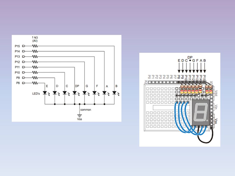
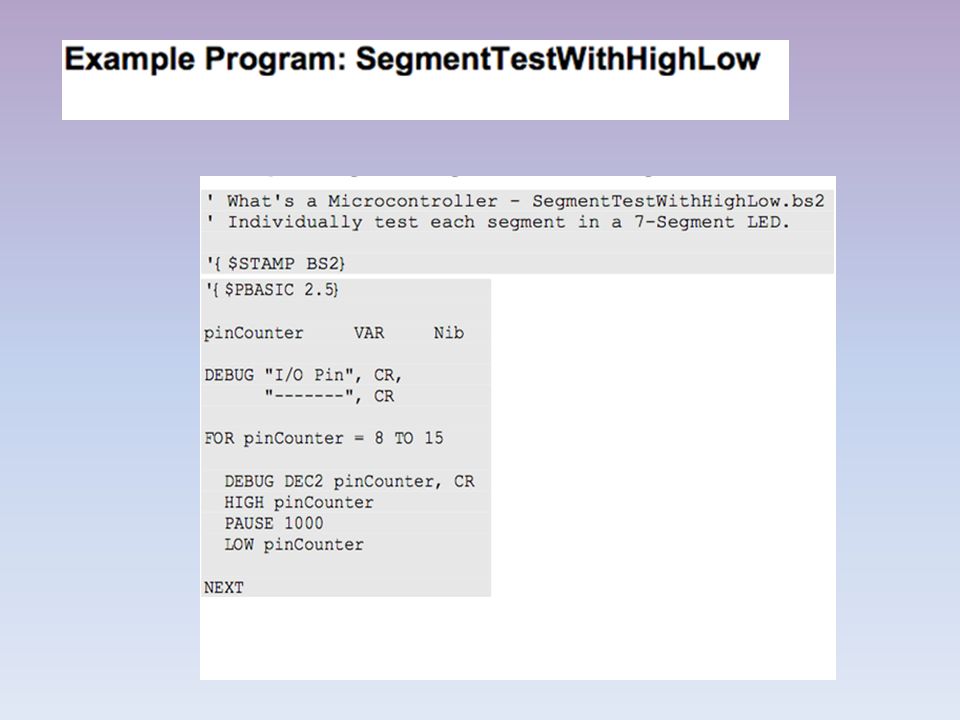
Controlling 7 segment display using Basic Stamp Objective:To build and control the 7-segment display LED circuit. Background: In this activity, you will connect the 7-segment display to the BASIC stamp, and then run a simple program to test and make sure each LED is properly connected. The HIGH and LOW commands will accept a variable as a pin argument. Therefore, they are placed in a FOR… NEXT loop, and index is used to set the I/O pin, high, then low again.

16
Equipment: 7-segment LED display Resistors – 1 kΩ (brown-black-red) Jumper wires Procedure: Build the circuit shown in figure.
 Jumper wires Procedure: Build the circuit shown in figure.")
18
Program and the BASIC Stamp by following the steps below: Enter and run SegmentTestWithHighLow.bs2. Verify that every segment in the 7-segment LED displays lights briefly, turning on and then off again. Record a list of which segment each I/O pin controls

20
Programming 7- segment display using Basic Stamp 2 Including the decimal point there are eight different BASIC Stamp I/O pins that send high/low signals to the 7-segment display. That’s eight different HIGH or LOW commands just to display one number. It requires more space in memory, so there are special variables used.

21
DIRH and OUTH Variable. DIRH DIRH VARIABLE OUTH OUTH VARIABLE

22
DIRH VARIABLE DIRH Variable that controls the direction ( input or output ) of the pins P8 – P15 DIR – Short for direction H – For high P8 – P15 DIRL – Also used. L – low for P0 – P7 Using DIRH Variable DIRH = % 11110000

23
% - following means binary number 11110000 – Each bit corresponds to a pin in the following order. %11110000 PIN15141312111098 0 INPUT 1 OUTPUT BACK

24
OUTH VARIABLE OUTH is a variable that controls the status of each output pin ( high or low ) for the pins P8 – P15 OUTH – HIGH ( P8 – P15 ) OUTL – LOW (P0 – P7 ) Using OUTH Variable OUTH = % 11110000
 for the pins P8 – P15 OUTH – HIGH ( P8 – P15 ) OUTL – LOW (P0 – P7 ) Using OUTH Variable OUTH = %")
25
% - following means binary number 11110000 – Each bit corresponds to a pin in the following order. %11110000 PIN15141312111098 0 LOW 1 HIGH BACK

26
Using DIRH and OUTH commands Look at the following commands now ! – OUTH = % 0 0 0 0 0 0 0 0 – DIRH = % 1 1 1 1 1 1 1 1 The first command: OUTH = %00000000 gets all of the I/O pins (P8 through P15) ready to send the low signals. If they all send low signals, it will turn all the LEDs in the 7-segment display off.
 ready to send the low signals. If they all send low signals, it will turn all the LEDs in the 7-segment display off..")
27
The I/O pins will not actually send the low signals until you use the DIRH variable to change all the I/O pins from input to output. The second command: DIRH = %11111111 sets all I/O pins P8 through P15 to output. As soon as this command is executed, P8 through P15 all start sending the low signal.

28
Write the OUTH command for the figure shown.

29
The picture shows number 3. For displaying number 3,the following pins to be set high. Refer the previous activitythe previous activity

30
For displaying 3 – Make A B C D G as 1 – Make F E DP as 0 From the figure we can write Hence the command is OUTH = % 11010110 P15141312111098 BAFGDPCDE 11010110

31
Look up command Used to write code The look up command lets you “ look up “ elements in a list. It will help you select an item from the list, or compare an item to a list of items. Command Syntax: LOOKUP index, [item1, item2,…], value

32
Example for LOOKUP command LOOKUP index, [7, 85, 19, 167, 28], value There are two variables used in this command, index and value. INDEX VALUE 0 7 1 85 2 19 3 167 4 28
![Example for LOOKUP command LOOKUP index, [7, 85, 19, 167, 28], value There are two variables used in this command, index and value.](http://images.slideplayer.com/26/8568192/slides/slide_32.jpg "INDEX VALUE")
33
LOOKDOWN COMMAND LOOKDOWN command compares a value with items in a list and informs the position (index) It is the reverse of the LOOKUP command. Command Syntax: LOOKDOWN value, comparison[item1, item2,…], index

34
Example for LOOKDOWN command LOOKUP index, [7, 85, 19, 167, 28], value There are two variables used in this command, index and value. VALUEINDEX 70 851 192 1673 284
![Example for LOOKDOWN command LOOKUP index, [7, 85, 19, 167, 28], value There are two variables used in this command, index and value.](http://images.slideplayer.com/26/8568192/slides/slide_34.jpg "VALUEINDEX")
35
PROGRAMMING WITH BASIC STAMP

36
SOLUTION: Since index is 2, in this example, the LOOKUP command places 19 into value, and that’s what the Debug Terminal displays.

37
PROGRAMMING WITH BASIC STAMP

38
SOLUTION The value of index in this case would be “3”.

Similar presentations


 Applications DC Characteristics & Operation Interfacing to.>")


 display by wiring.>")
, or seven-segment indicator, is a form of electronic.>")