Download presentation
Presentation is loading. Please wait.

1
MAE 343 - Intermediate Mechanics of Materials Tuesday, Aug. 24, 2004 Textbook Sections 4.1 – 4.3 Forces, Equilibrium, Failure

2
4.1 Loads and Geometry Steps of machine design process (Table 1.1) –Driven by functional performance specifications –Yield “best” material and geometry for strength & life –Step VI – Global Force Analysis Must be accurate, but difficult for new machines Must include surface and body loads, moments, reaction forces Surface forces may be concentrated or distributed in various patterns Step VII-Iterative design of each part (Table 1.2) –Based on local forces and moments from global analysis –Local force analysis based on concepts & equations of equilibrium
 –Driven by functional performance specifications –Yield best material and geometry for strength & life –Step VI – Global Force Analysis Must be accurate, but difficult for new machines Must include surface and body loads, moments, reaction forces Surface forces may be concentrated or distributed in various patterns Step VII-Iterative design of each part (Table 1.2) –Based on local forces and moments from global analysis –Local force analysis based on concepts & equations of equilibrium")
3
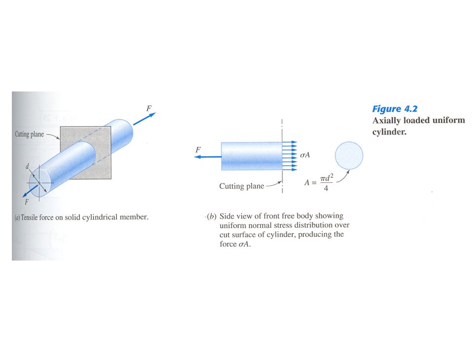
4.2 Equilibrium Concepts and Free- Body Diagrams (FBD) Six Equations of Static or Dynamic Equilibrium –Three force components along arbitrary x-y-z axes –Three moment components about arbitrary x-y-z axes Free-Body Diagrams (Figs. 4.2 and 4.3) –Cutting Plane isolates selected portion from the rest –Internal Forces on cutting plane replaced by system of equivalent external forces for equilibrium of free body –Internal force per unit area of cut face is defined as stress
 –Cutting Plane isolates selected portion from the rest –Internal Forces on cutting plane replaced by system of equivalent external forces for equilibrium of free body –Internal force per unit area of cut face is defined as stress.")
6
4.3 Force Analysis Design based on physical model of a machine –Analytical simplifications for reasonable effort –Accurate analyses in local regions of contact Basic factors to consider in force analysis –How forces and moments are applied on elements –How loads are transmitted through the structure and reacted –Likely failure modes and critical locations in the structure “Force Flow” or “Line of Forces” –Visualize lines from applied forces to supports –Identify critical locations for preventing failure

7
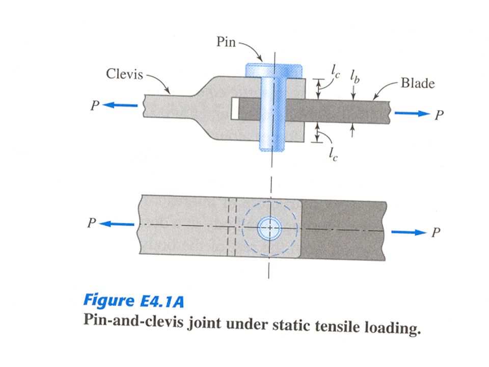
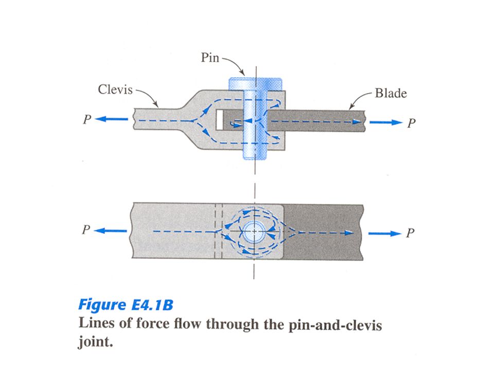
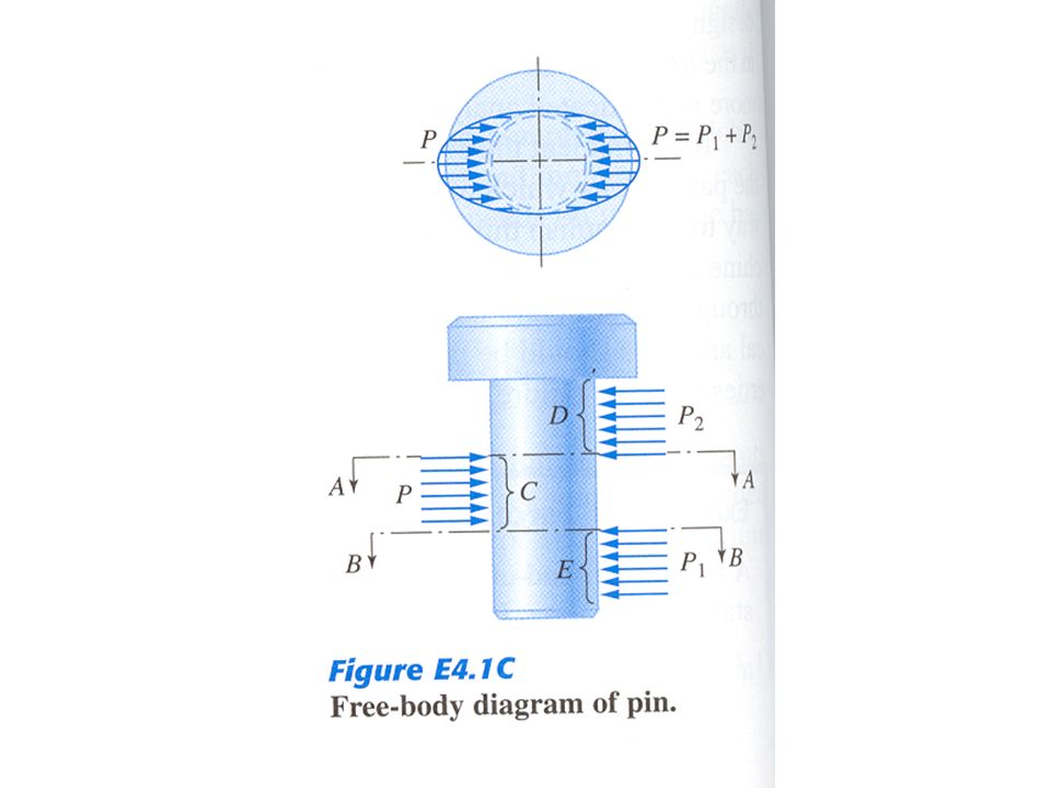
Example 4.1 –Force Flow through Pin and Clevis Joint Lines of force flow for uniaxial tension Free-Body Diagram (FBD) of the Pin –Distributed stresses along and around the bearing contact regions, C, D, and E –Depend on material, geometry, loading level Potential Failure Modes –Elastic deformation between clevis and blade –Yielding and/or ductile rupture –Brittle fracture across shear planes A-A and B-B
 of the Pin –Distributed stresses along and around the bearing contact regions, C, D, and E –Depend on material, geometry, loading level Potential Failure Modes –Elastic deformation between clevis and blade –Yielding and/or ductile rupture –Brittle fracture across shear planes A-A and B-B")
Similar presentations

 Spring 2008>")

 or has a constant velocity if originaly.>")


 Concentrated Force – applied to a point on a.>")


